
Abstract
Fast and accurate pile volume estimation is a very important basic problem in mining, waste sorting, and waste disposing industry. Nevertheless, for rapid changing or badly conditioned piles like stockpiles or landfills, conventional approaches involving massive measurements may not be applicable. To solve these problems, in this work, by utilizing unmanned aerial vehicles and unmanned ground vehicles equipped with a camera, we propose a collaborative framework to estimate volumes of free-formed piles accurately in short time. Compensating aerial- and ground views enable the reconstruction of piles with steep sides that is hard to be observed by single unmanned aerial vehicle. With the help of red-green-blue image sequences captured by unmanned aerial vehicles, we are able to distinguish piles from the ground in reconstructed point clouds and automatically eliminate concave on the ground while estimating pile volume. In the experiments, we compared our method to state-of-the-art dense reconstruction photogrammetry approaches. The results show that our approach for pile volume estimation has proved its feasibility for industrial use and its availability to free-formed piles on a different scale, providing high-accuracy estimation results in short time.
Introduction
Piles, usually free-formed, are one of the important material storing and managing forms in the industry. The pile volume is of great significance to scientific management, economic benefit assessment, and storage capacity assessment. With the accelerating development of large-scale storage bases, modern management techniques for stock storage are required. However, current approaches to calculating pile volume are likely to involve massive measurements or high computational complexity, leading to high labor cost or time usage. For situations where stock changes rapidly or piles in bad conditions, like port or landfill, they may not be applicable. To solve the above problem, various studies have been conducted. Current approaches to calculating pile volume are divided mainly into three categories: Manually reshape the pile into a regular shape, to calculate the pile volume. Use a total station theodolite (TST) to measure the entire pile and calculate an approximate volume. Densely reconstruct the entire pile with oblique photography, photogrammetry, or light detection and ranging (LiDAR) to get the detailed mesh, and then compute the volume of mesh.
1,2
However, these approaches require either intensive human resource or high computational power, causing high time usage in volume calculation. For better illustration, a
At present, reconstruction methods are intensively used in pile volume estimation, reconstruction results from oblique photography can provide high-resolution measurement results with accuracy at centimeter level and is widely used and accepted in geosciences and geomatics industry as a reference of survey and mapping, 3 –5 but the high-resolution reconstruction also leads to more time-consuming and inefficient methods. In some reconstruction that does not require high resolution, visual simultaneous localization and mapping (SLAM) also have a wide range of applications. SLAM, with allowing reconstructing maps in real time at the expense of accuracy, are some based on conventional visual, 6 –9 some based on deep learning, 10,11 and some based on multisensor fusion. 12 –14 In a wide range of scenarios, those approach engaging SLAM with a single agent has many defects, including limited sensing range and viewing angle, low data storage capacity, and high onboard computational complexity. By implementing multi-agent, SLAM can simply overcome these difficulties; however, there are challenges in mutual pose correction and information perception among multiple robots, but simply implementing multi-agent SLAM will introduce other problems. For applications like pile volume estimation, reconstruction results from single observe view may be incomplete and does not meet the requirements to accurately estimate the volume.
In this work, we proposed a multi-agent aerial–ground collaborative framework to quickly recover the sparse three-dimensional (3D) information of the pile in unexplored surroundings with marker optimization and lastly calculate the pile volume by the heightmap. Compared with the dense mapping of a single robot, collaborative framework measures the pile volume in a short time with high accuracy. Our main contributions are summarized as follows: We propose a novel framework of aerial–ground collaborative sparse reconstruction. This framework can easily combine the information for multiple views and generate a global sparse reconstruction of the environment. The keyframe poses of the unmanned aerial vehicle (UAV) and the unmanned ground vehicle (UGV) are optimized by tag-based pose optimization. We build a new mechanism of tag-based estimation for map scale estimation and interagent local map alignment. Using the tag pose and dimension as prior information, the distance between tag center and the observing camera center can be estimated, and then the duplicated points in the merged map are removed and local maps are aligned and merged into the global map. The proposed method is applied in pile volume estimation for the first time. In comparison with the single-agent setup, the results show that the overall accuracy of our method is improved significantly.
Related works
This section reviews advances in collaborative SLAM and UAV photogrammetry in a wide range of areas. Early multiple agents are based on the relative positioning and the expensive base-mobile stations positioning system, then gradually to UGVs and UAVs collaborative SLAM. However, lacking the map scale, those methods cannot be used to estimate the real measurement. Our work is based on tag-based estimation for map scale estimation and thus can be used in volume estimation.
Collaborative SLAM
Many research studies have been conducted on collaborative SLAM. For example, Jo et al. 15 proposed a method for obtaining the interagent distance based on real-time kinematic (RTK) data of different agents to realizing the relative positioning among agents and reducing the positioning error in the relative positioning process. However, in the case of a weak global position system (GPS) signal, the positioning accuracy of GPS will be worse than that of the conventional sensor like inertial measurement unit (IMU). Some researchers have attempted to use the RTK positioning system by selecting one agent as the RTK base station and others to be RTK mobile stations. While RTK devices are relatively expensive, this attempt is difficult to be widely applied.
Surmann et al. 16 proposed a framework that integrates a UAV and a UGV to do SLAM in a relatively complex scenario. In their work, the UGV and UAV equipped with sensors such as LiDAR and vision camera, and the merged map is generated when a similar transformation is done between dense mapping resulting from UAV and a point cloud from UGV. And then Zhang et al. 17 proposed an approach based on environmental perception, which only relied on the cameras of UAV and UGV, and then combined with semantic segmentation to jointly construct the global map.
In some other works, Schmuck and Chli 18 and Van Opdenbosch and Steinbach 19 proposed that multiple agents run SLAM independently, transferring local maps together with keyframe data to a central server, when visual overlaps are detected between the keyframes from different agents, the server merges the local map into a global map. Their fundamental approach does not correct the map scale and thus cannot be used in volume estimation. Karrer et al. were also proposed a collaborative visual-inertial SLAM, 20 which allows agents to share all information with the central server to improve the performance.
UAV photogrammetry
Since the high accuracy of UAV photogrammetry or oblique photography, many types of research have been conducted. Mokroš et al.
1
used poles for scale reference and done monocular 3D reconstruction with a single UAV, obtaining a volume error about
Aerial–ground collaborative sparse reconstruction
Framework of aerial–ground collaborative sparse reconstructionWe build our UAV and UGV collaborative framework directly on oriented FAST and rotated BRIEF (ORB-SLAM), 7,8 since its high integrity for the entire SLAM system including visual odometry, back-end optimization, loop detection, and map construction. As shown in Figure 1, (a) the aerial end is comprised of a set of UAVs equipped with a monocular camera and GPS. (b) The ground end consisting of a group of UGVs with a monocular camera and AprilTag 21 printed on its surface. The tracking module in each agent tracks map points and the pose of corresponding unmanned vehicles, sending keyframes to mapping module to create a local map. (c) Central server listens for inbound connections from UAVs and UGVs, receiving transferred data from both ends, merging maps from each agent to create the global map. A tag detection procedure is running on central server polling for keyframes and detects for any presenting AprilTag.

Overview of the proposed collaborative sparse reconstruction framework. In our design, the entire system consists of three major participants: (a) the aerial end, (b) the ground end, and (c) a central server.
The aerial–ground collaborative sparse reconstruction algorithm has three separate phases, which are as follows: Each agent uses an onboard computing platform to perform the visual SLAM algorithm independently and continuously estimate six-degree-of-freedom (6-DoF) rigid transformation information together with the scale factor. When the central server detects AprilTag in any keyframe, the coordinate of corresponding observing UAV and observed UGV can be unified. Meanwhile, because of the prior knowledge of the tag’s dimension, the scale factor can be inferred, and the local map is then merged into one consistent global map. Also, the keyframe poses of the UAV and the UGV are optimized by tag-based pose optimization. The optimized pose is then broadcasted to all agents, and a global bundle adjustment is performed to minimize the offset of the global map.
Tag-based map scale estimation
After SLAM procedures on agents were initialized and local maps were created on agents with their first keyframe pose as their coordinate origin, whenever a tag is detected, the tag pose can be estimated by solving a perspective-n-point problem. If we know the tag dimension as prior, we can estimate the distance between the tag center and observing camera center, this distance is used as the scale reference in the following tag-based optimizations. The 6-DoF rigid transformation matrix can be written as

And transformation matrix

We can then compute the scale factor

Keyframe sequence pair in tag-based optimization procedure.

Tag-based interagent local map alignment
Besides the scale factor can be recovered from tag prior, the tag is also used to align corresponding maps when a tag pose

where A 0 and G 0 are the coordinate system of the first keyframe of the corresponding UAV and UGV, respectively. The mapping and localization results from a single UGV and a single UAV are shown in Figure 3(a) and (b), respectively. Figure 3(c) shows the result from collaborative reconstruction with a UGV and a UAV. With tag-based optimizations, the duplicated points in the merged map are removed and local maps are aligned and merged into the global map. Three different views are provided for each map.
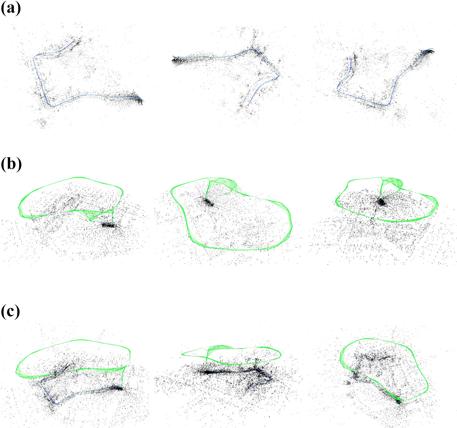
Constructed maps from the single agent and collaborative reconstruction with three views provided for each map. (a) Local map from single UGV, (b) local map from single UAV, and (c) merged global map with tag-based optimization of collaborative reconstruction with UAV and UGV. UAV: unmanned aerial vehicle; UGV: unmanned ground vehicle.
Pile volume estimation overview
In this section, we describe our designed framework for pile volume estimation. Figure 4 shows the block diagram of our designed framework for pile volume estimation. Firstly, a multi-agent reconstruction module continuously analyzes the input video stream, detects, and collects keyframes to generate a sparse point cloud for the captured area. Then the point cloud and keyframe are passed to the ground segmentation module. For each keyframe, we perform the ground segmentation module to calculate the probability that a map point belongs to the ground plane class. After the ground point cloud is collected, random sample consensus (RANSAC) 22 is used to fit a ground plane. Once the best fit ground plane is calculated, points will be reprojected to a newly generated coordinate system based on the ground plane and voted into a fine grid to get a heightmap.

Overview of our designed framework for pile volume estimation. The entire system is built by five main modules.
In the end, the pile volume can be calculated by summing all elements in the heightmap with positive values and some proper scaling.
Ground plane estimation
The correct selection of the ground plane is considered important in volume estimation since the ground plane is used directly in heightmap generation. We use a simple encoding–decoding network to perform segmentation on every possible keyframe, we resize every frame to the size of
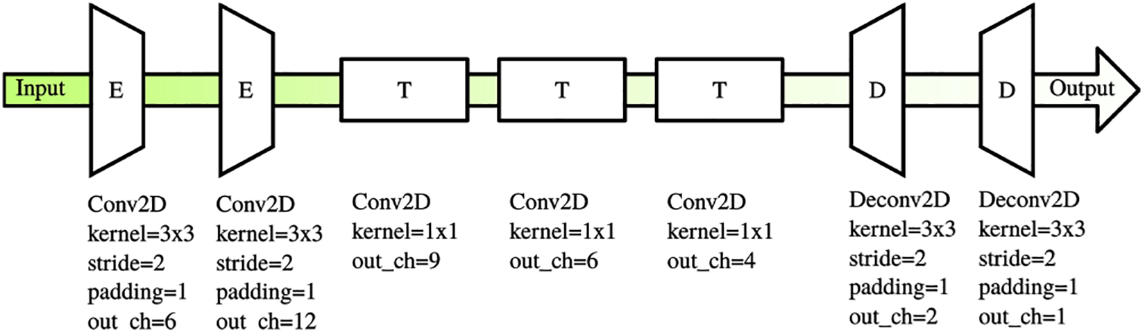
The network structure for ground segmentation.
For each map point, we maintain a list of co-visible keyframes. We use a voting mechanism to determine a map point whether belongs to ground or pile, each keyframe votes for the map point, the category with highest votes with more than
Then the determined ground point cloud is passed into the RANSAC algorithm to fit the parameters of the ground plane

Ground segmentation and plane estimation. The ground points are shown in green, pile points are shown in red, whereas the undetermined points are marked in yellow. (a) Segmentation input, (b) segmentation output, (c) overlaid image, (d) side view of segmented point cloud, and (e) point cloud with estimated ground plane.
Heightmap generation
The heightmap is used to calculate pile volumes, and to generate height from the pile point cloud, we create a temporary coordinate system on the estimated ground plane
Then the minimal rotated rectangle
For a map point

An example of the heightmap generation. The brighter location is higher. (a) Generated heightmap and (b) heightmap with holes filled.
After heightmap H is generated, the pile volume V can be easily calculated by summing all elements in the heightmap with positive values multiplied by the grid resolution r.

Experiments and discussion
In this section, we describe our experiments and evaluations of our approach. We conducted experiments on a wide range of piles, including large-scale landfills and other stockpiles, to evaluate the speed, accuracy, repeatability, and robustness of our proposed approach.
To evaluate the localization accuracy of our proposed approach among multiple agents, we evaluate our aerial–ground collaborative reconstruction approach in a school campus.
We built a data set with several piles with our collaborative multi-agent setup at different flight heights and UGV on the ground. Based on the data set we built, we conducted the following experiments. Figure 8 is a demonstration of the UAV and UGV used in our experiments in collaborative setup, the UGV is marked with a tag. The top view of the landfill and rock pile in our experiments can be found in Figure 9. For comparison, we captured extra image sequences for the photogrammetry method to produce dense reconstruction results.

The photo of (a) UAV and (b) UGV in collaborative setup used in our experiments. UAV: unmanned aerial vehicle; UGV: unmanned ground vehicle.

Top view of the piles used in experiments. (a) The small-scale rock pile and (b) the large-scale landfill.
Accuracy evaluation on collaborative reconstruction
In this section, we describe our evaluations on collaborative reconstruction and analyze the accuracy of the mapping and localization procedure. The UAV in this experiment is DJI A3 flight controller-driven drones, equipped with NVIDIA Jetson TX1 onboard computers. And the UGV is driven by Intel NUC. We used a laptop with Intel i7-8750H processor, NVIDIA GeForce 1070 graphics card, and 8 GB RAM as a central server. The overall system based on the robot operating system, and with wireless image transmission and radio station, UAV and UGV transmit video data to the central server for real-time SLAM and optimization algorithms. This experiment is conducted in a school campus.
Table 1 presents that the average errors of a single UAV and UGV SLAM are
Comparison of the translational error between single- and multi-agent reconstruction.

UAV: unmanned aerial vehicle; UGV: unmanned ground vehicle.
Comparison of the rotational error between single- and multi-agent reconstruction.

UAV: unmanned aerial vehicle; UGV: unmanned ground vehicle.
Volume estimation performance on small-scale rock pile
In this experiment, we evaluate the estimation accuracy and speed of our approach on a rock pile as shown in Figure 9(a). We use the calculated volume by a dense method as a reference, the dense mesh is reconstructed from 186 images in 5 different viewing angles at 60 m above ground. Both dense reconstruction and our approach are performed on an Intel i7-8700 K PC with NVIDIA GTX 1070Ti graphic cards.
The estimated values and time usage are listed in Table 3. Sequences 1–3 are three different captured image sequences of the same pile at a flight height of 10, 20, and 30 m, respectively. As shown in the table, flight height has an implicit impact on the estimation accuracy and a direct impact on the estimation time, since higher flying height provides wider viewport coverage, but less texture detail. The optimal flight height is subjected to the pile scale and the pile texture.
Evaluation results on small-scale rock pile.

As we can see, the estimation time of our approach is shorter than the acquisition time and is several times shorter than the time usage of dense method, which means with the parallelization of data acquisition and estimation procedure, the estimated values can be read right after acquisition procedure is finished. Compared to the dense method, our approach is fast and accurate, with a minimum volume error of

Comparison of reconstructed models from dense reconstruction and heightmap. (a) 3D model rendered from the height map and (b) 3D model rendered from dense reconstructed mesh.
Volume estimation performance on large-scale landfill
In this experiment, we evaluate the accuracy of the pile volume estimation method on a large-scale landfill. This landfill mainly serves for daily waste disposal, with some part of the pile covered with plastic sheets, and the top view of this landfill is shown in Figure 9(b).
The estimated values and time usage are listed in Table 4. Sequences 1–3 are three different captured image sequences of the same pile, in which sequence 1 is captured at a flight height of 60 m, and both sequences 2 and 3 are captured at a flight height of 30 m. Here we also use the calculated volume by the dense method as a reference, the dense mesh is reconstructed from 1677 images in 5 different viewing angles at 60 m above ground.
Evaluation results on large-scale landfill.

The conclusion is similar to volume estimation performance on a small-scale rock pile, with collaborative sparse reconstruction method, the estimation time and reconstruction time are shortened. Compared to the dense method, our approach is fast and accurate, with a minimum volume error of
Conclusion
In this study, we propose an innovative and efficient aerial–ground collaborative reconstruction framework to solve the problem of pile volume estimation. In this framework, we present tag-based optimizations to recover map scales and inter-map transformation matrix, so that local maps from different agents can be aligned and merged into a global map. We have conducted a series of experiments on both large-scale and small-scale piles. This method is proved to work reliably on free-formed piles and estimate the volume of the pile with a reasonable accuracy which is capable of industrial usages and is meaningful to stock management and solid waste recycling industry.
Footnotes
Declaration of conflicting interests
The author(s) declared no potential conflicts of interest with respect to the research, authorship, and/or publication of this article.
Funding
The author(s) disclosed receipt of the following financial support for the research, authorship, and/or publication of this article: This work was supported by the National Key R&D Program of China (no. 2018YFB1305200), Science Technology Department of Zhejiang Province (no. LGG19F020010), and National Natural Science Foundation of China (no. 61802348).