
Abstract
This article investigates a difficult problem which focuses on the external disturbance and dynamic uncertainty in the process of trajectory tracking. This article presents a robust adaptive fuzzy terminal sliding mode controller with low-pass filter. The low-pass filter can provide smooth position and speed signals. The fuzzy terminal sliding mode controller can achieve fast convergence and desirable tracking precision. Chattering is eliminated with continuous control law, due to high-frequency switching terms contained in the first derivative of actual control signals. Ignoring the prior knowledge upper bound, the controller can reduce the influence of the uncertain kinematics and dynamics in the actual situation. Finally, the experiment is carried out and the results show the performance of the proposed controller.
Keywords
Introduction
Robot is a nonlinear and uncertain system. The controllers are intend to enable the manipulator to track the desired trajectory with ideal dynamic quality or at a specified position. 1 –6 The uncertainty of robot parameters and the existence of nonparametric uncertainty factors lead to the change and instability of the system. 7 –11 It is well known that the nonlinearity and uncertainty in the robot dynamic control, such as friction, external disturbance, and variable load, will reduce the robustness.
However, the main methods for the robust control are sliding mode control, fuzzy control, and other intelligent controllers. Recently, the combination of fuzzy control and sliding mode control has become the focus of current research. Sliding mode control has been widely used in application. 12 –14 Fuzzy sliding mode control can reduce the fuzzy rules in fuzzy control and reduce the chattering of sliding mode control. The chattering of sliding mode control under the condition of uncertainty and disturbance in robot dynamics model is described in the literature. 2,8,15 –20 In Zheng and Liang, 21 a fuzzy adaptive method is described on a 3-degree of freedom (DOF) planar robot. Due to the nonlinear and uncertain problems existing in the motion process of planar robot, an adaptive fuzzy sliding mode control method based on PID sliding die surface is proposed. The output gain fuzzy sliding mode is controlled, the chattering phenomenon is avoided, and the simulation verification is carried out. The validity of this method is verified. In Rezoug et al., 22 the control method combining fuzzy sliding mode control and dynamic control method is applied to the differential wheeled robot, and the simulation and experimental research are carried out to verify the proposed controller. In Matraji et al., 23 an adaptive second-order sliding mode controller is introduced, a robust controller for ignoring disturbance is established. An adaptive hyper-torsion algorithm is designed, and the experimental results show that the proposed controller can accomplish the predetermined trajectory well.
The adaptive terminal sliding mode control strategy is also appearing in robotic field, especially in the dynamic control. In Riani et al., 24 the terminal sliding mode control has also been deeply discussed, unlike the traditional sliding mode variable structure control. The terminal sliding mode controller has a nonlinear sliding mold surface. However, the tracking error of the system can have faster convergence speed compared with the traditional sliding mode control. 25 –30 In Wang et al., 31 in order to ensure the good control performance of cable-driven manipulator in complex uncertainty environment, a new continuous fractional order non-singular terminal sliding mode control scheme is proposed, which does not depend on model and system dynamics, and has high practical value. In Asl et al., 32 based on the principle of non-singular terminal sliding mode control, a new control law is established, a kind of non-trace Kalman filter is proposed for robot manipulator, which can withstand the uncertainty of external disturbance and noise, and the simulation verification is carried out on 6-DOF manipulator.
Considering the disturbance and dynamic uncertainty in the trajectory tracking, the robustness of the dynamic controller is discussed and a new controller is proposed. This article is organized as follows: firstly, the dynamic parameter equation of the robot is deduced under the condition of disturbance and dynamic uncertainty. In the second part, a fuzzy terminal sliding mode controller based on low-pass filtering is designed in this article, which can guarantee the fast convergence of the trajectory tracking and its stability is proved by Lyapunov stability theorem. In the third part, the validity and practicability of the proposed controller are verified by MATLAB simulation and physical experiment. In the fourth part, the experimental results show the performance of the proposed controller and compared with the PID controller. Finally, the results are discussed and the robustness of the proposed controller is conducted.
System model and objectives
Trajectory of the robot manipulator

where

Among them,

Without considering friction and uncertainty, the kinetic equation of robot is established by Lagrange method for an n-DOF series arm with strong moment action on each joint (22):

Therefore, the task space trajectory in the process of robot trajectory tracking can be described as xd , the joint input torque τ is used to achieve the appropriate tracking of the task space trajectory, and ensure the stability and effectiveness of the entire tracking process.
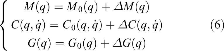
In practical application, due to the existence of a large number of uncertainties, it is difficult to obtain the robot dynamics model as shown in formula (3); if these uncertainties are fully taken into account, then the following complete kinetic model is obtained (1)

In the formula (5),
When all the kinetic parameters are known, according to the kinematics equation (2)

The formulas (8) and (9) can be obtained by using formula (7), so that the relationship between the dynamic control law and the motion space can be obtained as follows


Low-pass filter and sliding mode controller design
For external disturbances and jitter generated by sliding mode controllers, the following low-pass filters are designed 33

where
The ideal position instruction is


where e,

It can be obtained by formulas (5), (11), and (12)


where
The first and second items in the equation (14) help to improve closed-loop stability and transient performance, and more importantly, they help compensate for tracking errors caused by kinematics and dynamic uncertainties. The last term in equation (14) guarantees the existence of the sliding mode to improve the robustness of the robot system, especially when the system reaches the sliding surface, the robot system is absolutely robust to any disturbance. Considering the nonlinear manipulator, over the formula (9), the control law is designed as follows

The joint dynamics equation can be obtained by the formula (16) as follows

Given the conditions for the dynamic uncertainty of the closed-loop system, the entire equation can be represented as shown in equation (18)
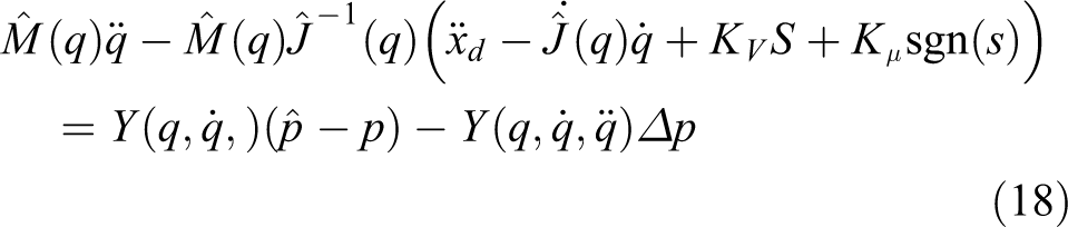
Among them,
Proof
Consider the following Lyapunov functions

It can be concluded

Assuming

Therefore, the control law (16) can keep the control system on the sliding surface

where q is the joint position and qd is the desired joint position. The terminal sliding surface is shown as follows

p and q are positive odd numbers and meet the condition

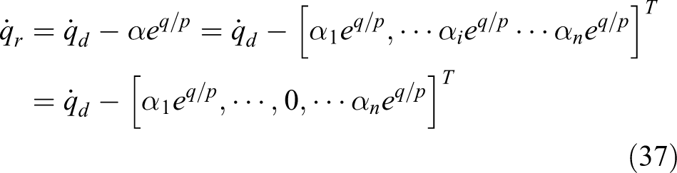
Considering the following control input

The sliding surface can be defined as

where

The solution of the equation (24) for a limited amount of time ti can be given in the following form

Among them, p and q satisfy the equation (23); then, ti is the tracking error to reach zero after the terminal sliding mode is obtained. Speed errors is just as shown


where

The vector
Applying formulas (29), (30) to (17), we can get

We select the Lyapunov function

After a differential

Select control input

Bringing the equation (35) into the equation (34), we can get

where
When
From (22) and (27), if E and Ė are bounded, then B is bounded. Suppose,
This ensures that the system tracking error converges quickly, and that
When
When
From (29), we can get
where from (30), we can get

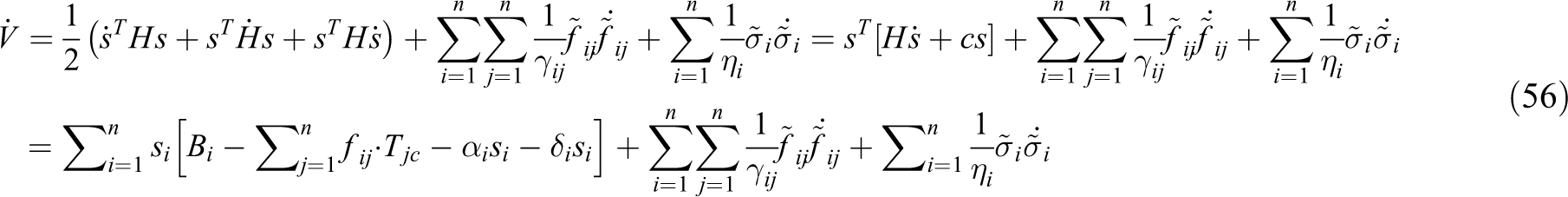
In this example,

where
Remark 1
In this article, singularity can be avoided in the following ways
Choose

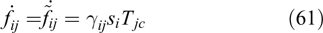
It is easy to verify that in the case of
Multiple input and multiple output fast terminal sliding mode control for robotic manipulators
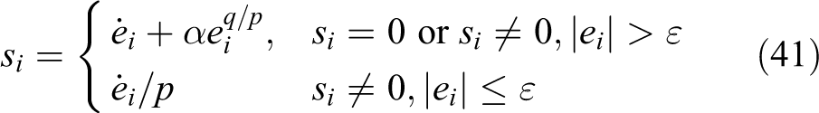
Although the above terminal sliding mode controller can drive the system tracking error converges to zero. For a limited amount of time, it has several drawbacks, like dynamic quality and “chatter” phenomenon. In order to enhance the dynamic quality and ensure the system tracking error converges to zero, each

And

Fuzzy rules can be determined as follows.
By selecting weighted average de-fuzziness, the output of fuzzy inference system can be written
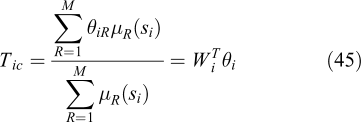
And M is the amount of rules,

The robotic operating system can be expressed as

Fuzzy terminal sliding conditions can be met, so

Then

Therefore, the system tracking error is guaranteed to converge rapidly under the conditions of
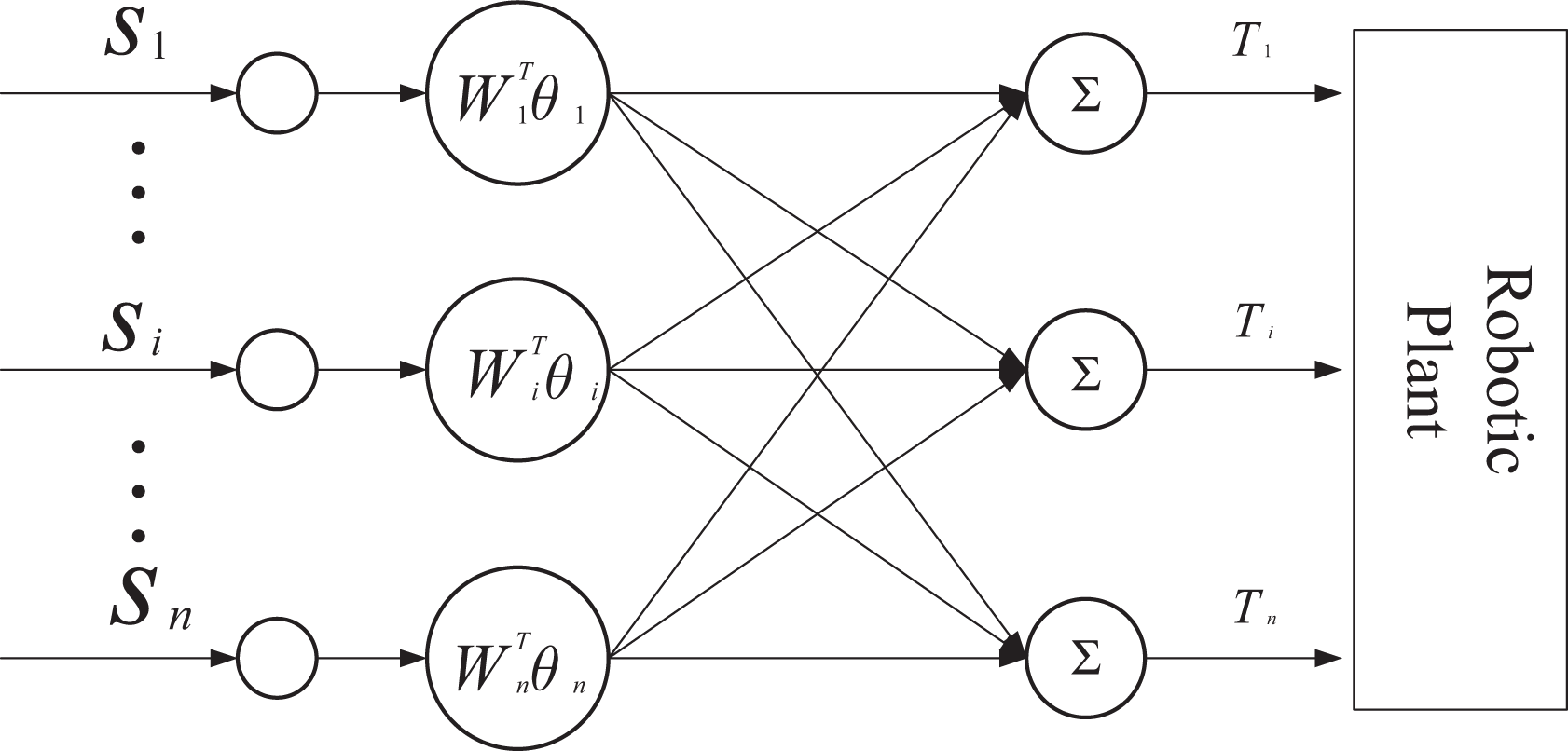
The structure of a MIMO FTSMC.
Multiple input and multiple output adaptive fast terminal sliding mode control for robotic manipulators

Figure 2 show the fuzzy terminal sliding mode control based on the low-pass filter (LFFTSMC).
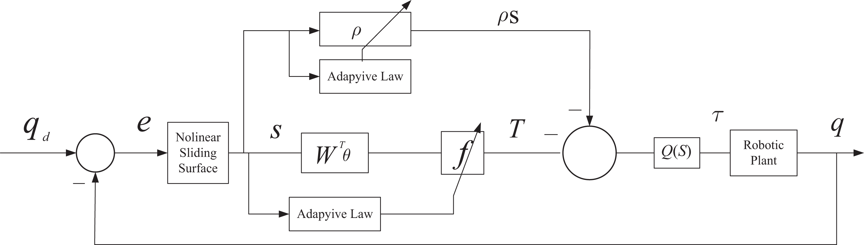
Fuzzy terminal sliding mode control block diagram based on low-pass filter.
The output of adaptive fuzzy controller is

With the optimal factor

Defines the error of the normalized factor of the fuzzy output variable

Then


Define

where H is a symmetrical positive definite matrix.
Due to

Due to

Owing to

Then

The adaptive law is

Then

Since
When
Simulation
In this part, the MATLAB2014 Toolbox is used to establish the robot model and carry out the simulation and the sampling time of the system is 0.005 s. The initial path used in the simulation is shown in the function (64)

Because of the uncertainty of robot dynamics model, the system model is applied to the parameter uncertainty matrix. In order to meet the stand, we choose the following stand:
The sampling grid time for the entire process is 0.005 s. As shown in Figure 3, after adding a filter, the LFFTSMC control approach can achieve better results than the other two controllers. More important, the whole tracking effect makes the tracking error reach the tracking effect of 0.2 mm. PID control method can be used to realize track tracking very well, but the whole process is not very good to achieve characteristics. The kinematics and dynamics parameters of the robot are shown in Tables 1 and 2.

The trajectory tracking error in different controllers. (a) The errors of the three kinds of controllers are along the X-axis. (b) The errors of the three kinds of controllers are along the Y-axis. (c) The errors of the three kinds of controllers are along the Z-axis.
Robot mechanism parameters.

Robot dynamics parameters.

The main characters of the controllers are just as follows: The controller mentioned in this article can achieve the superior error tracking value. Because of the phenomenon of “chattering” in the control of the slip mode structure, it can also be improved in the optimization of dynamic uncertainty equations. The error distribution of the controller mentioned in this article is more uniform and concentrated, which shows the stability and effectiveness of the controller. In addition, the proposed LFFTSMC retention error converges to zero along the X-, Y-, and Z-axis.
Figure 4 depicts the input torque of each joint in the whole input process, especially after adding external disturbance, each joint carries on the effective signal input in 16 s. The input torque is effectively optimized, reducing the tracking error of the whole tracking process. As can be known from Figure 4, the parameter selection, adaptive law use and the use of fuzzy logic model of low-pass filter play a certain effect in the whole process. The following conclusions can be obtained by comparison.

SMC, AFTSMC, LFFTSMC joint input torque.
In terms of control torque, sliding mode controller (SMC) has serious chattering phenomenon. AFTSMC method and LFFTSMC method basically overcome the chattering phenomenon. Compared with AFTSMC, LFFTSMC advantage is not particularly prominent.
In the aspect of error tracking, three methods position tracking method position tracking error has no particularly large error, showing good robustness; SMC, AFTSMC, and LFFTSMC in the control accuracy, LFFTSMC shows better control accuracy. The speed error of SMC method fluctuates obviously, while AFTSMC and LFFTSMC have good stability and dynamic quality.
From the torque diagram, AFTSMC and LFFTSMC can quickly reach the stable state, overshoot time, and other dynamic performance indicators to meet the requirements. The deficiency is that the two methods in the dynamic response time almost have no difference.
Experiment
The experimental device is composed of 5-DOF manipulator, six-dimensional force sensor, external PC, and non destructive inspection (NDI) measurement system. The experimental trajectory of the end effect point of the manipulator in Cartesian space is captured by using the NDI system, and the mark is fixed on the manipulator.
The six-dimensional force sensor measures the external force change of the manipulator during execution, marking the characteristics of the whole execution process. The hardware structure of the robotic arm is shown in Figure 5(b). The open version of the controller that is the network client is connected to the CAN connection based on the CAN protocol. The real-time external PC as a network server is extended in real time based on RTAI Linux. The two devices communicate at a frequency of 500 Hz, the industrial controller sends the actual bonding position and speed, and sends the motor current to the external PC and the external PC to answer to send the reference joint position and speed. The JR3 six-axis wrist force/torque sensor is mounted on the manipulator of the right-hand operator of the 5-DOF manipulator and connected to the PC through a DAQ board managed by the RTAI system. The analog voltage generated by the force sensor is obtained by a dedicated real-time thread, which is also responsible for reducing the impact of the measured noise by filtering each channel using the 10th-order moving average filter.

The experiment setup. (a) Welding robot manipulator and other measurement system. (b) The hardware structure of manipulator. (c) The robot mechanism diagram. (d) The robot controller, respectively.
In the robot manipulator to establish mark point, in the process of robot operation, the use of NDI for effective tracking, especially in the process of research, A, B, C and other special feature points, using JR3 for effective dynamic force tracking, robotic kinematics and kinetic parameters are shown in Tables 1 and 3. Using experiments based on AFTSMC and LFFTSMC controller, the NDI measurement system realizes the position tracking of the manipulator, and the position error can be seen below. JR3 six-axis wrist force/torque sensor to achieve the manipulator of the power tracking, in the process of track tracking, to achieve X-, Y-, Z-direction of force measurement, the specific tracking effect from the following:
The fuzzy ruler.

In the course of the experiment, the JR3 six-axis wrist force/torque sensor is used to measure the change of torque in the whole research process, in the process of track tracking.
The results Figure 6 –8 show the proposed controller can obtain the better performance during the trajectory tracking, and the performance was enhanced through the dynamic controller.
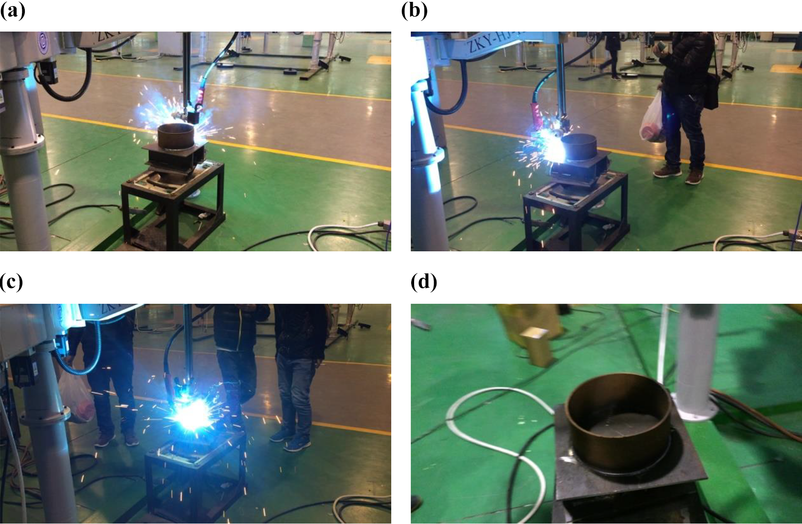
The experiment tested on 5-DOF manipulator with dynamic disturbance. DOF: degree of freedom. (a) The initial point. (b) The motion in process. (c) Another motion point. (d) The terminal point.

The force measured by the force system during the proposed controller and the PID experiment.

The errors that were measured during the LFFTSMC experiment and the PID method.
Conclusion
A MIMO-fuzzy terminal sliding mode control with low-pass filter was integrated. The novel controller performed better than others. The main contributions of this article are just as follows: In this article, the low-pass filter and the fast terminal sliding mode controller were combined to reduce the trajectory tracking error to zero in a limited time. The position and velocity characteristics of the robot joints wrest effectively processed, and the input torque was effectively optimized through the new controller to ensure the tracking process and dynamic characteristics. The chattering phenomenon and the external disturbance and kinetic uncertainty in the process of track tracking in the fast terminal sliding mode control are optimized and controlled. The external disturbance and dynamic uncertainty on trajectory tracking was reduced, and the input torques were optimized. The new experimental device and modern test equipment were introduced. Micro–macro robot, NDI, and six-dimensional force sensor were used to perform the result of the proposed method. And the results showed that the tracking accuracy was realized within 0.3 mm considering the dynamic uncertainty and disturbance.
Footnotes
Data availability statement
Some or all data, models, or code used during the study were provided by a third party (Nanjing University of Science and Technology Robotic Institution). Direct requests for these materials may be made to the provider.
Declaration of conflicting interests
The author(s) declared no potential conflicts of interest with respect to the research, authorship, and/or publication of this article.
Funding
The author(s) disclosed receipt of the following financial support for the research, authorship, and/or publication of this article: This research was supported by National Key Research and Development Program of China (2018YFB1308301) and National Natural Science Foundation of China (nos 61374133 and 61673205).