
Abstract
Trajectory tracking control of autonomous underwater vehicles in three-dimension always suffers disturbances such as input time delays and model uncertainties. Regarding this problem, an integral time-delay sliding mode control law is proposed in this article with dividing the vehicle’s input time delays model into cascade system consisting of a kinematics subsystem and a dynamics subsystem. Based on the established pose error equation and velocity error equation, a suitable Lyapunov–Krasovskii functional is given to analyze and guarantee the global stability of the whole system under reasonable assumptions. At last, comparative simulations are presented to demonstrate the effectiveness of the proposed method.
Keywords
Introduction
Trajectory tracking control for underactuated autonomous underwater vehicles (AUVs) has strict constraints on time. 1 Considering the practical application of the project, the delays of the AUV’s actuators such as propellers and rudders will cause the delays in output of control force and torque. The most direct effect is system overshoot increases, poor control effect, even causing system divergence instability. At the same time, the input time delays cause the system characteristic equation to have an infinite number of eigenvalues and become an infinite dimensional system. Therefore, the trajectory tracking control strategy based on the traditional Lyapunov stability theory is no longer applicable. Time delays and nonlinear coupling bring challenges to system control research. 2 –4
Underactuated AUV trajectory tracking control system is a typical time-delay strongly nonlinear system. The stability analysis and robust control of time-delay systems have important theoretical and engineering significance. To make the system stable under bounded uncertainty, the form of free matrix is improved using Leibniz–Newton formula, and a convex optimization algorithm is proposed. 5,6 Wu et al. 7 considered the influence of the Leibniz–Newton formula when replacing the delay term 8 and introduced the free weighting matrix (FWM) to eliminate the influence. The introduced FMW was determined by linear matrix inequality (LMI), and the criterion with less conservatism was obtained. Sun et al. 9 proposed an augmented Lyapunov functional containing triple integral terms. By introducing an FWM, 10 a new time-domain correlation stability criterion was derived using LMI.
In practical applications, the AUV thrusters and rudders have time-delay characteristics that cannot be ignored, especially for Euler–Lagrangian systems with actuator delays, parameter perturbations, and external bounded disturbances. Sharma et al. 11 designed tracking controllers for known and unknown inertial forces, introduced prediction terms to deal with the delay in control input, and adopted Lyapunov–Krasovskii function to prove semi-globally consistent ultimately bounded tracking. Mazenc et al. 12 solved the problem of state feedback stabilization of feedforward system with input delay. Based on the time-varying change of coordinates and the functional of Lyapunov–Krasovskii, the designed controller could still keep the input state stable when parameters were uncertain. This result is applicable to any given constant delay, and the designed controller is applied to the formation tracking control of unmanned aircraft. Han et al. 13 studied the robust sliding mode control (SMC) problem for discrete singular systems with time-varying delays, parameter uncertainties, and nonlinear disturbances. By constructing the appropriate discrete sliding surface function, the corresponding sliding mode dynamics is obtained and chattering is reduced.
Zhou et al. 14 address the motion parameter skip problem associated with three-dimensional trajectory tracking of an underactuated AUV using backstepping-based control. The problem of stability analysis for continuous-time/discrete-time systems with time-varying delays has been studied. 15 A new delay partitioning method is presented, which partitions the delay interval into nonuniform subintervals. An SMC law is proposed for discrete systems with time-varying delays and external disturbances. The delay weight dependence stability of LMI form is obtained using the free weight matrix method. 16,17 The backstepping control technique is designed as the nominal controller for integral sliding mode control. To enhance the tracking performance of the system, an adaptive technique and a new disturbance observer based on sliding mode technique are developed and integrated into the integral sliding mode control (ISMC). 18 Liang et al. 19,20 present a novel swarm control framework for path following of multiple underactuated unmanned marine vehicles with uncertain dynamics and unmeasured velocities. A center-of-swarm guidance scheme is further employed for collision avoidance and obstacle avoidance. In recent years, the globally finite-time control strategy is proposed, which globally stabilizes all trajectory-tracking errors in the finite time. 21 Although there have been a lot of research results on the stability and control strategy of time-delay systems, there are very few studies on vehicles trajectory tracking control for time-delay nonlinear system.
To reduce the influence of input time delays and disturbances on the trajectory tracking control system, this article presents an integrated SMC strategy based on unknown bounded time delays. Firstly, simplify the vehicle input time delays model. The trajectory tracking pose and velocity error equation are obtained. Secondly, the system is divided into a cascade system consisting of a kinematics subsystem and a dynamics subsystem. Underactuated AUV trajectory tracking control is transformed into tracking error stabilization. The integral time-delay sliding mode control law (TDSMC) is designed for the trajectory tracking position and velocity error. Finally, a suitable Lyapunov–Krasovskii functional is given to prove that the vehicle trajectory tracking error converges to zero. The stability criterion of the system is obtained.
Problem formulation
In this section, firstly, an underactuated AUV five-degree-of-freedom motion model with input delays is established, followed by the transformation between the earth-fixed frame and the body-fixed frame. Secondly, “virtual underactuated AUV” is established. Further, the vehicle three-dimensional trajectory tracking error equation is obtained. The vehicle trajectory tracking control is converted to tracking error stabilization.
The AUV model and frame transformation
To analyze the three-dimensional motion of the vehicle, two coordinate systems are defined, as shown in Figure 1. E and B represent the earth-fixed frame and the body-fixed frame of AUV, respectively.
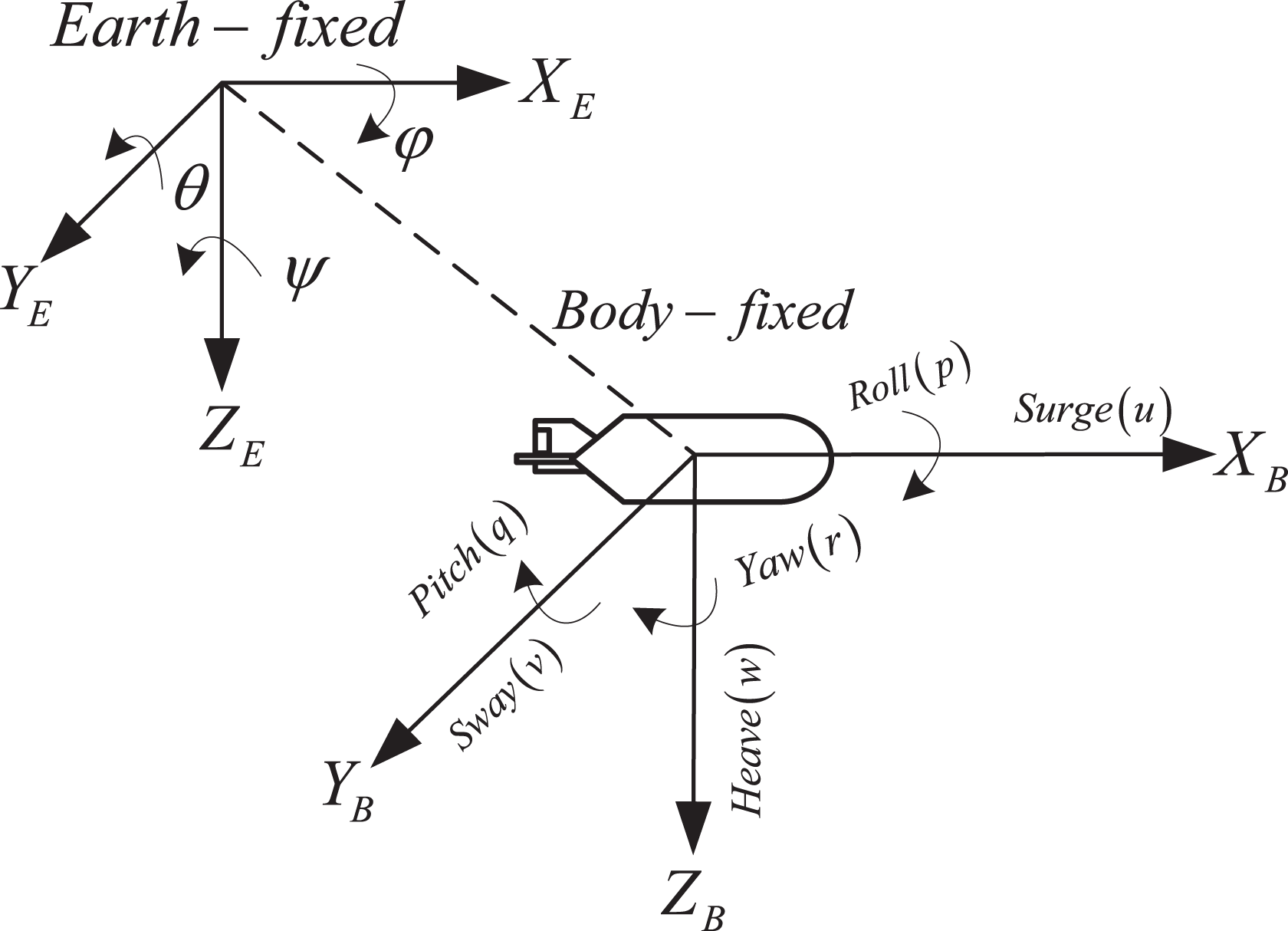
AUV model. AUV: autonomous underwater vehicle.
The matrix vector descriptions of the AUV kinematics and dynamics mathematical models are


where
Kinematic model:

Dynamic model:

where
Underactuated AUV satisfies the following assumptions:
Assumption 1
The speed and control inputs of the underactuated AUV are bounded, that is,
Assumption 2
When
Assumption 3
Establishment of trajectory tracking error equation
The desired motion state of the vehicle under the desired trajectory is described by establishing a “virtual underactuated AUV.” 23 The motion state of the virtual AUV is obtained by deriving the position and posture information of the desired trajectory at the current time. Defining the desired position and attitude information of the vehicle is as follows

where the desired attitude is determined by the desired position


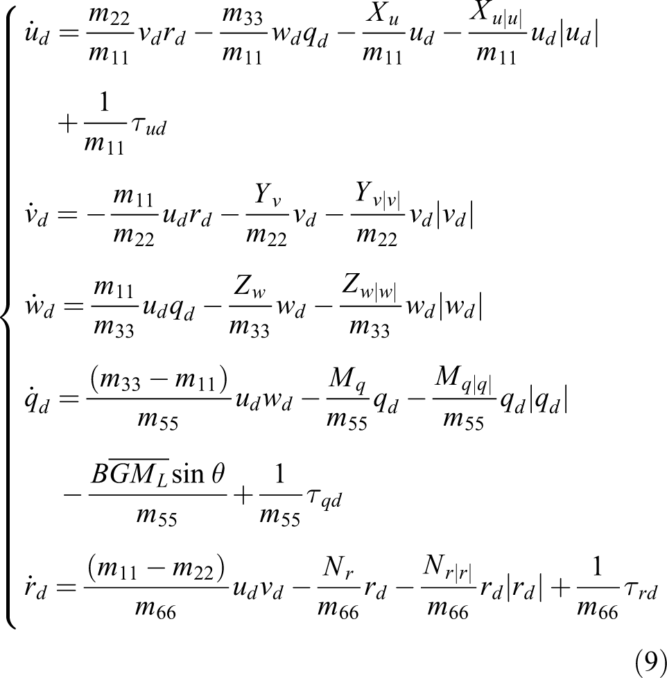
The virtual underactuated AUV five-degree-of-freedom model is established as follows

Define the trajectory tracking pose and velocity error variables as follows

The vehicle trajectory tracking pose error variable is derived along the trajectories equations (3) and (8). Get the tracking pose error equation as follows:


The vehicle trajectory tracking speed error variable is derived along the trajectories equations (4) and (9). The tracking speed error equation is obtained as follows


To facilitate calculation, the trajectory tracking position error equation is written as the following vector form

Defining the line speed error

Rewrite equation (11) into the following vector form

where

where
To facilitate subsequent calculations, the following two lemmas are introduced.
Lemma 1
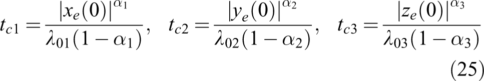
For a given limited time globally stable system 24,25

where
Lemma 2 (Barbalat)
Considering function
Controller design
The AUV model and frame transformation
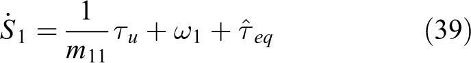
Step 1
To achieve the target of trajectory tracking, the following first-order nonlinear sliding surface is designed to make the position error

where
The derivatives of equation (20) are obtained as

While

Expand the above formula, that is,

Since the position error equation state is completely measurable, designing an equivalent control law eliminates positional errors. Combining equation (3) and
where
From Lemma 1, the designed desired control law
Considering that

The derivatives of equation (13) are obtained as

From equations (24), (26), and (17), we have
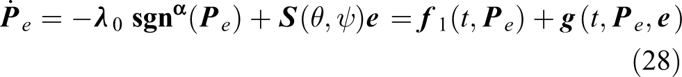
From equation (27), we obtain

Therefore, the underactuated AUV trajectory tracking time-delay control system can be represented by two subsystems as follows

It is known from the stability theorem of cascade system 25 : If the two subsystems are globally uniformly ultimately bounded, then the system equation (30) is globally uniformly ultimately bounded.
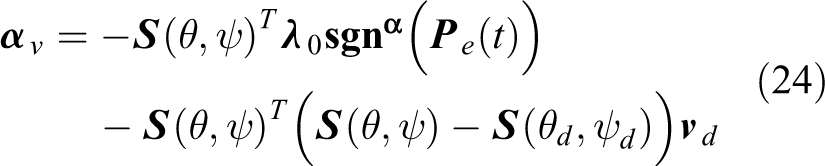
Design of virtual controller
In step 1, the stabilization problem of trajectory tracking error has been transformed into the stabilization problem of virtual control error. Now controllers need to be designed to stabilize the subsystem

Considering that the input time delay has an essential effect on the system is the hysteresis output of the control force and the control torque, further delaying the change in motion state. Therefore, the input time delay can be equivalent to the state time delay of the system. From equation (31)

where T is an unknown bounded state time delay equivalent to the input time delay, and the upper bound is
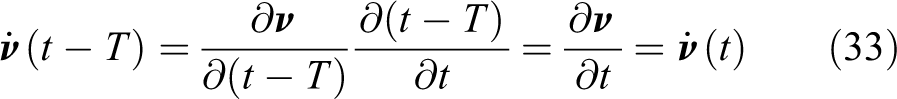
From equations (33) and (32), we obtain

Step 2
For the roll virtual control error, the following first-order nonlinear sliding surface is defined as

The derivatives of equation (35) are obtained as


While
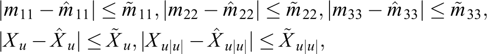
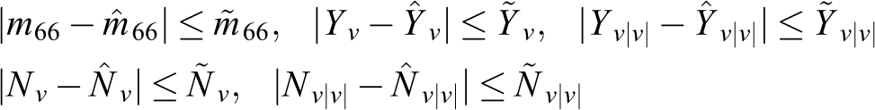
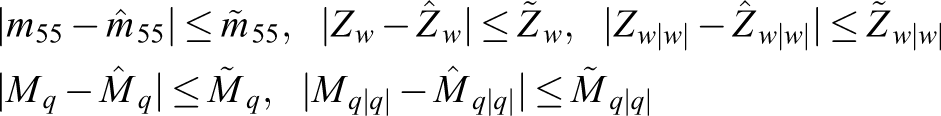
where “ ^ ” is the estimated value of the model uncertainty parameter. “∼” is the upper bound of the model uncertainty parameter, and satisfies the following boundary conditions
From equations (38) and (24), we have
where
Choose the following saturation function to weaken the buffet caused by the sign function in the sliding mode

where
Since the subsystem

where
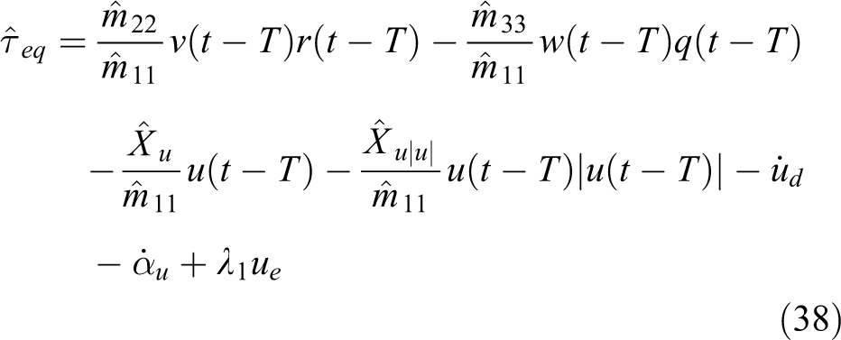
To eliminate the effects of time delays, uncertainty parameter, and external disturbances, the longitudinal control law is designed as
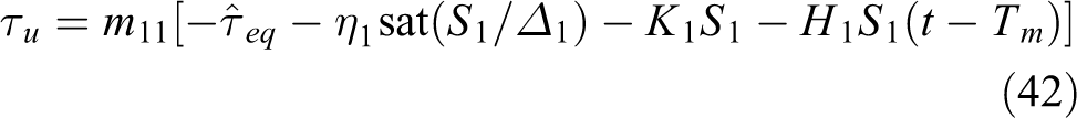
where
Step 3
For the pitch virtual control error, the following second-order nonlinear sliding surface is defined as

The derivatives of equation (43) are obtained as

Taking the derivatives of equation (27)
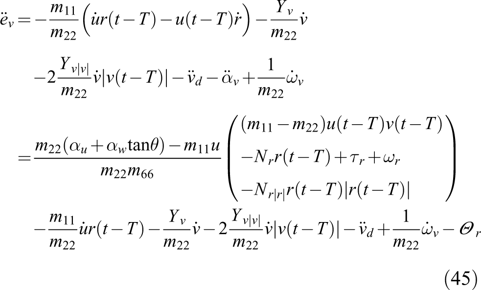
Submitting equation (45) into equation (44) produces

where

Design the following constant velocity approach law to eliminate the negative effects of parameter uncertainty of subsystem

where

To eliminate the effects of time delays, uncertainty parameter, and external disturbances, the pitch control law is designed as

where
Step 4
For the yaw virtual control error, the following second-order nonlinear sliding surface is defined as
The derivatives of equation (49) are obtained as

Similar to step 3, we can obtain

where

Design the following constant velocity approach law to eliminate the negative effects of parameter uncertainty of subsystem

where

To eliminate the effects of time delays, uncertainty parameter, and external disturbances, the yaw control law is designed as

where
System stability analysis
Theorem 1
For the underactuated unmanned underwater vehicle (UUV) three-dimensional trajectory tracking system, if the UUV kinematic model (3) and the dynamic model (4) satisfy Assumptions 1 to 3, then the sliding surface designed by equations (35), (43), and (49) and the control law shown in equations (42), (48), and (53) when the control gain matrix satisfies
Proof
Define the sliding surface vector as
The Lyapunov–Krasovskii functional of the integral term with time delay is chosen as follows

where

From

From Jensen integral inequality,
26
for any vector

Substituting equations (57) into (56) produces

To guarantee that the system is globally uniformly ultimately bounded, the gain matrix of designed control law must satisfy the following conditions

While

From equation (60), we obtain
Simulation results and analysis
To verify the performance of the underactuated AUV time-delay control algorithm designed in this article, and robustness to model parameters uncertainty and disturbances, the spiral descent trajectory was selected, and the following two comparative simulation tasks were designed:
The true value of time delays is 0.5 s. Considering that it may face a worse situation, the upper bound of the time delay is 0.52 s. Select TDSMC given in equations (42), (48), and (53).
The true value of time delays is 0.5 s. The upper bound of the time delay is 0.52 s. Select SMC as

The model parameters used in the simulations are
27
Underactuated AUV desired trajectory and related parameters.
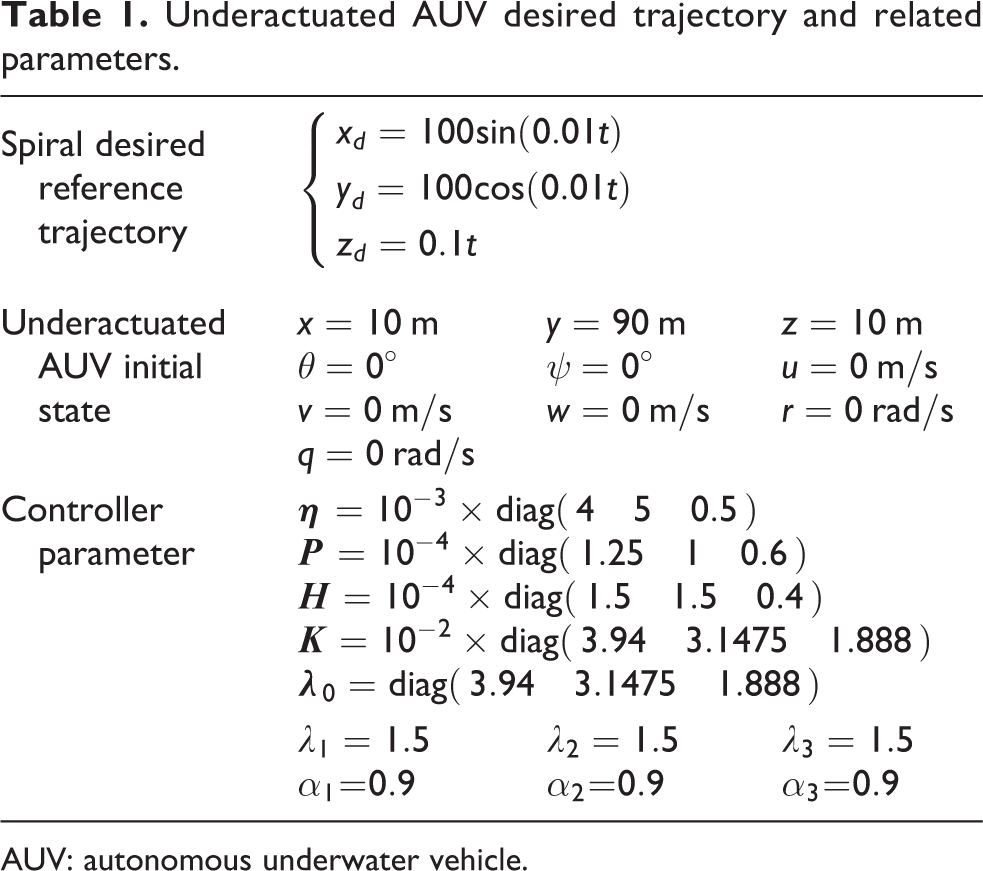
AUV: autonomous underwater vehicle.
Simulation results are shown in Figures 2 to 9.

Three-dimensional trajectory tracking curve with time delays: (a) time-delay sliding mode control and (b) sliding mode control.

(a to c) Position tracking error with time delays.

(a to c) Trajectory tracking translation speed response curve with time delays.

(a to c) Velocity tracking error with time delays.
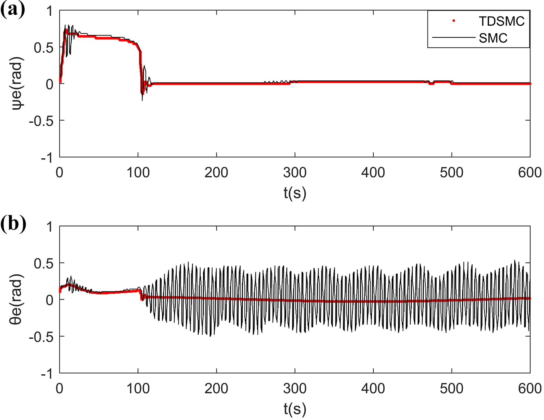
(a and b) Attitude angle tracking error with time delays.

(a and b) Trajectory tracking angular velocity response curve with time delay.
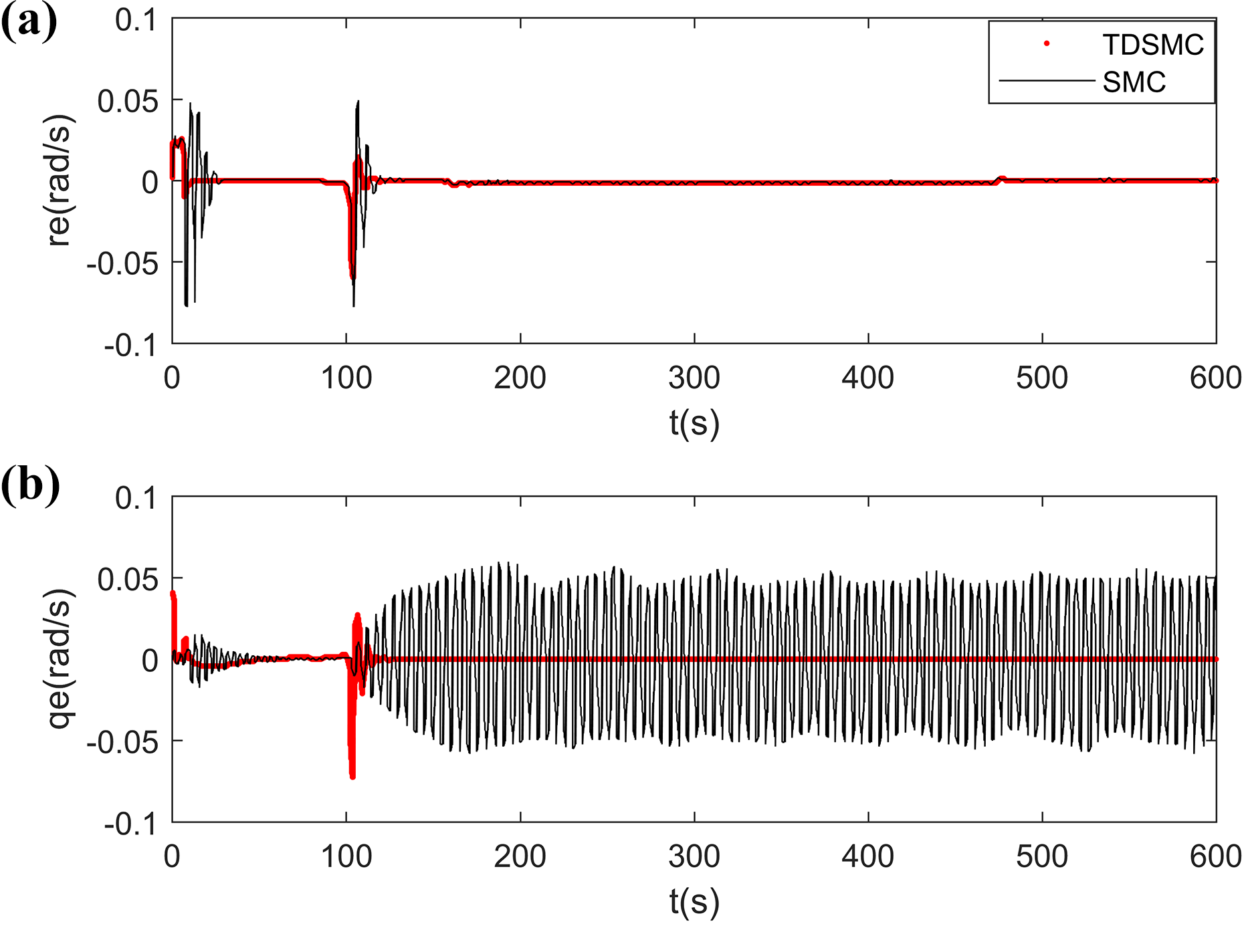
(a and b) Angular velocity tracking error with time delay.

(a to c) Control input force and moment with time delays.
In the simulations, the control effects between the TDSMC and the existing conventional SMC are compared. Among them (a) is TDSMC and (b) is SMC.
Figure 2 compares the dive spiral trajectory tracking of the time-delay sliding mode controller and the sliding mode controller in the same time delays. It can be revealed that under the control of the designed TDSMC, the vehicle achieves smooth tracking of the spiral dive reference trajectory. And it has novel robustness to model parameter perturbation and disturbances. The vehicle also tracks the reference trajectory under the control of the SMC. However, under the control of SMC, there is a large oscillation in the entire tracking process. The above analysis shows that the control parameters of the SMC are greatly affected by the input time delays.
Figures 3, 4, and 5 are position tracking error with time delays, trajectory tracking translation speed response curve with time delays, and velocity tracking error with time delays, respectively. From the simulation results of TDSMC, it can be revealed that within 100 s after the start of the task, due to the large position tracking error, the longitudinal and transverse velocities respond quickly to track the desired position. After 100 s, the underactuated AUV tracks the desired reference trajectory. The linear velocities also converge to the expected value.
Figures 6, 7, and 8 are attitude angle tracking error, trajectory tracking angular velocity response curve, and angular velocity tracking error with time delays, respectively. From the simulation results of TDSMC, it can be revealed that within 100 s after the start of the task, after the task starts 100 s, AUV tracks the position and starts spiral dive. The pitch angular velocity q and the yaw angular velocity r have a larger response than before. The final angular velocity error also converges to zero. Comparing the simulation results of SMC, it can be revealed that there is a very serious oscillation on the attitude angle tracking. This is consistent with the severe oscillations that occur on the actual trajectory in Figure 2. SMC cannot control the vehicle to smoothly track the desired trajectory.
Figure 9 is the control input of the underactuated AUV under the two controllers. In the trajectory tracking control of the vehicle, although the actual actuator delay is small, if the controller design is simplified by directly ignoring the time delays, it will cause severe control oscillations. This oscillation may cause significant wear, shorten the service life, and even not under command on the actuator hardware.
Conclusion
This article presents a trajectory tracking SMC for underactuated AUVs with time delays, model parameter uncertainty, and external disturbances. The integral TDSMC law is designed for the trajectory tracking pose and velocity error of the cascade subsystem. Based on the Lyapunov–Krasovskii functional, the stability conditions of the LMI form are obtained, which guarantees that the designed controller is globally stable. The simulation results reveal that under the designed controller, the vehicle realizes the trajectory tracking control target under the constraint condition. The control accuracy has reached the expected target.
Footnotes
Declaration of conflicting interests
The author(s) declared no potential conflicts of interest with respect to the research, authorship, and/or publication of this article.
Funding
The author(s) disclosed receipt of the following financial support for the research, authorship, and/or publication of this article: This study was supported with funding from Jiajia Zhou, Tao Chen and Di Wu.