
Abstract
Fault detection and diagnosis become one of today’s hot spots, which describes that image information is an important form of fault information, it can quickly through the image processing technique, and can accurately extract the characteristic signal. This article selects the color of the particle image, the integrated use of digital image processing, pattern recognition theory, the characteristic parameters of tribology knowledge, as well as the extraction, optimization, and digital; verifies the feasibility of iron spectrum of abrasive fault recognition, and provides a new efficient ferrographic wear particle image recognition method. Firstly, the grindstone image of the original color diesel engine was preprocessed, and the grindstone image of the ferrograph was identified by directly selecting grindstone from the preprocessed ferrograph image and selecting the target grindstone. According to the two types of abrasive particles, the characteristic parameters were first classified, and then the values of the characteristic parameters were obtained through the training and learning of the sample abrasive particles. In view of the large number of characteristic parameters of ferro-spectrum abrasive particles, this article determined the characteristic parameters suitable for the identification of abrasive particles in this article through the feature optimization and proved the correctness of the identification of characteristic parameters of abrasive particles through the test.
Introduction
With the development of science, technology, and productivity, modern mechanical equipment has become increasingly large and complicated, especially with the emergence of mechatronics, automation, and intelligence, making the scale of the production system larger and larger, the performance indicators in various aspects higher and higher, and the functions more perfect. 1 People use robots instead of manual work. 2 The vision system of charge coupled device (NAO) robot takes color images through the camera for image analysis and processing. The color images collected by the camera of NAO robot have different degree of noise, which affects the image quality and further affects the subsequent image processing, resulting in the decrease of recognition accuracy. 3 Therefore, in the image visual processing, the image must be de-noised to achieve accurate segmentation, so as to correctly identify targets or obstacles and obtain important position information, which is conducive to further positioning, tracking, and other tasks. 4 NAO robot collects the images by a camera to obtain external information, and the images are affected by changes in external light. Therefore, we should look for an image processing algorithm that can adapt to and overcome changes in light intensity during image processing. Sometimes, the image processing needs to achieve the real-time task requirements, the visual system design algorithm should also be more concise, less computational. At the same time, people on the mechanical equipment reliability requirements are also higher and higher. Mechanical equipment condition monitoring and fault diagnosis technology cover a wide range of contents, 5 including vibration and noise monitoring technology, functional monitoring and diagnosis technology, oil analysis and diagnosis technology, and so on. Oil analysis technology is a kind of abrasive particle analysis technology in essence, which includes two categories: one is the analysis of the deterioration degree of oil; the other is the analysis of the number, size, shape, color, composition, and changes of abrasive particles in the oil. 6 Oil analysis and diagnosis technologies mainly include oil physical and chemical indicators and contamination detection, ferrography analysis, spectral analysis, magnetic plug analysis, Fourier transform infrared spectrum analysis, particle count, and so on. 7 Due to the unique advantages of ferrography analysis, it has opened up a new field of research and application for wear monitoring of mechanical equipment with oil abrasive particles as the analysis object and has become an important abrasive particle analysis technology. 8 Iron spectrum technology of the 1970s is a new wear particle analysis technology; the spectral analysis is mainly used for analysis of mechanical lubrication metal content in the power system, and it is mainly used for judging the wear condition of mechanical equipment, but the spectral analysis of serious deficiencies, 9 for example, could not tell the sensitivity to large-sized particles, could not observe grinding-grain morphology, and could not observe quantitative analysis of the different grinding particle size distribution and other equipment is expensive. Since the parts of most mechanical equipment are made of iron and steel, a new idea was proposed to use magnets to absorb the abrasive particles in the oil. Through repeated tests and studies, a series of ferrographs were made, which resulted in the formation of ferrography, a new oil analysis technology. As iron spectrum analysis is in the application of computer image processing technology and artificial intelligence technology, 10 computer and information processing formed with the combination of modern iron spectrum analysis, the core of it is based on wear particle image automatic recognition and classification, so as to realize the intelligent diagnosis of wear fault, and the key is for grinding grain of automatic recognition based on digital image processing techniques. In the process of image processing, various image processing methods are used to digitize the images to be analyzed, so as to construct characteristic parameters that reflect image characteristics, and then image recognition. A large number of practices have proved that computer image recognition technology is of great significance to improve the accuracy of ferrography analysis, shorten the analysis time, and reduce the workload of analysts. 11
With the continuous development of computer image processing technology and the intelligent development of ferrography analysis technology, the majority of scientific and technological workers have made certain achievements through unremitting research. The following is an in-depth analysis of the research progress and existing problems of abrasive particle identification technology at home and abroad. There are many research institutions in China, such as China University of Mining and Technology, Tsinghua University, Nanjing University of Aeronautics and Astronautics, Wuhan University of Technology, and Xi’an Jiaotong University, which are studying the expert system for particle identification. The research contents are as follows: wavelet theory, fractal theory, and color; the waviness, surface roughness, and shape error of friction pair and abrasive particle surface were separated by wavelet theory. The surface roughness parameters of friction pair surface and abrasive particle surface are calculated automatically by computer image analysis technique. Many foreign scholars have also studied the abrasive particle identification technology. British scientists have developed an expert system for computer-aided particle analysis, which combines the expertise of experts to classify particles according to their morphological characteristics, determine the names of each particle, and prioritize them according to their characteristics. 12 Through artificial intelligence method and expert system, the system lists the type table of abrasive particles and corresponding graphs, judges the wear status and gives the recommended treatment suggestions, and predicts the introduced software technology system called FAST, which was later modified into FASTPLUS. It can save the ferrograph image in the optical disk database, and can view at any time, and can directly print out the analysis report sheet after compared with the ferrograph image observed. Scholars from the University of Western Australia and James Cook University have made remarkable achievements in studying the surface morphology and morphological parameters of abrasive particles, but they have adopted neural networks, fractal theory, and fuzzy mathematical methods for theoretical research. Monitoring the navy’s development using LaserNetFines optical grits can be done by online monitoring, and off-line analysis can also be its principle to use the laser diode after exposure to oil in electronic camera, which will generate the image principle used for grinding-grain recognition, and to determine the oil characteristics of the reflected. 13 The monitor USES laser diodes that capture texture features under a microscope that are not fully reflected. It provides information about the type and severity of equipment failure by analyzing benign and active abrasive particles in the oil. It is able to determine the particle size between 5 mm and 100 mm all the concentration of the abrasive grain, for more than 20 microns large grinding grain can use neural network techniques will be collected abrasive is divided into four types of wear: normal abrasive, cutting wear, severe sliding wear, fatigue wear and tear, and identify the oxide, fiber and bubbles. Lockheed Martin has been developed based on LaserNetFines batch processor tactical defense systems, which is installed at Rushmore ship. Spectro company will LaserNetFines integrated into the group of expert system through the computer processing of different detection methods (such as infrared spectroscopy, emission spectrum, and iron spectrum instrument) information fusion is analyzed. American CSI OilView instrument is developed and can measure the particle size distribution, but there is no powerful LaserNetFines that can classify grits.
Xi and Wenkui proposed that ferrography technology is a technology that can be used to detect the characteristics of machine wear particles and infer their health status. 14 With the development of online ferrography technology, the grindstone image is obtained by using image processing technology to automate the detection process. However, it has been found that captured images often contain defocus and low brightness. A recovery framework is proposed to solve this problem. The main idea is to extract the edge of the object, amplify it with the nonlinear gain factor, and then combine it with the input image to produce the enhanced image for further analysis. When the content and brightness of image information are maximized, the meta-heuristic search is used to optimize the parameters used in the process. Experimental results from the processing of real-world wear particle images in lubricating oil circuits have shown qualitative and quantitative improvements in reinput images. Xingping Dong proposed a new sub-Markov random walk (RW; sub-algorithm) with labeled priors for seed image segmentation, 15 which can be understood as a traditional RW on a graph with auxiliary nodes added. On this basis, we combine the proposed sub-algorithm with other commonly used RW algorithms. 16 This unified view will make it possible to transfer internal discovery between different RW algorithms and provide new ideas for designing new RW algorithms by adding or changing secondary nodes. To verify the second advantage, we designed a new subalgorithm with tags to solve the segmentation problem of slender objects. Experimental results show that the segmentation effect of natural and composite images based on branchlets is better than that of existing seed image segmentation algorithms. 17 Then, a scholar proposed a new algorithm of alternate minimization image segmentation. Based on the similarity between Ambrosio–Relli model and Perona–Malik model, a new explicit alternative minimization algorithm is proposed. The Euler–Lagrange equation of the Ambrosio–Relli model is modified to have a sharper edge. The influence of parameters was studied. Numerical results show the effectiveness of the model. 18
Aiming at the requirements of engine fault diagnosis and combining the characteristics and advantages of ferrography analysis technology, this article studies and develops an expert system of engine fault diagnosis based on ferrography analysis technology. The main idea is to combine computer image processing and identification technology with ferrography analysis technology, and according to the expert system designed in this article to identify the type of abrasive particles and fault causes, the realization of ferrography automatic analysis improves the accuracy and efficiency of engine fault monitoring and diagnosis.
Proposed method
Main contents of ferrography technology based on image processing
Ferrography is generally divided into qualitative analysis and quantitative analysis.
Qualitative analysis method refers to experts in the field of ferrography analysis, who observe the total amount and size of abrasive particles deposited on ferrography, as well as the composition, number, and size of typical abrasive particles according to their long-term research. 19 Accumulated comprehensive determination of equipment wear status and location experience. Because this method can only be done by experts in the field, it is time-consuming and laborious and lacks objectivity.
Quantitative analysis method of abrasive grains.
Quantitative analysis method based on the total number of abrasive particles:
Quantitative criteria selection
Large grinding particle straight reading DL . It is sensitive to graininess in oil samples.
Wear intensity indexIs
,
Quantitative trend analysis: The technical quantitative analysis method of ferrograph analysis technology generally adopts the trend analysis method, and the independent variables are selected as the running time of various machines, the vehicles with running mileage, the cycle of regular maintenance machines, and the selection criteria of the above dependent variables. 20 Common methods include value valve method, line valve method, autoregressive time series automatic modeling method, fuzzy comprehensive evaluation method, and multivariate linear clustering analysis method.
Quantitative analysis method based on the distribution of grinding particle size: When extracting the distribution characteristic parameters of the grinding graininess, the hardware equipment adopted must be able to accurately count the grindstones within each particle size range contained in the oil sample. 21 The image analysis system applied in ferrography technology consists of CCD television imaging system, optical imaging system, and computer system. The optical imaging system first amplifies the field of view of the abrasive grains or abrasive grains on the ferrograph, and then the CCD camera converts the optical information into electrical signals and images them on the computer screen, which usually refers to the microcomputer with image processing capability. 22
It can be seen that the quantitative analysis of ferrograph mainly determines the relationship between the composition and type of abrasive particles by analyzing the changes of the total amount of abrasive particles in ferrograph and wear state, and then determines the wear state and position of mechanical equipment based on the conclusions obtained. Therefore, quantitative analysis is an objective analysis of abrasive wear.
General steps of ferrography technology based on image processing
The process of intelligent identification of abrasive particles is divided into four stages: data collection, data description, formation of interpretation theory, and testing theory. First is data collection. Since the current image recognition technology cannot reach the capability of computer recognition, the design should be based on auxiliary recognition, focus on data collection, and gradually approach to computer automatic recognition. 23 Especially in the case that the problem of grinding particles sticking to each other has not been solved, it is more necessary to use the artificial image segmentation technology to obtain more reliable grinding particle parameters. 24 The detailed steps are shown in Figure 1.

Flowchart of abrasive analysis.
As can be seen from Figure 1, there is manual intervention in each step, which can ensure that the error of the computer can be corrected manually if the computer cannot automatically separate the grinding grains. By marking the abrasive particles, and according to the order of marking, all the abrasive particles can be measured and analyzed. Ferrographic image recognition technology is the computer image processing technology to join ferrographic quantitative analysis calculation; a piece of iron spectrum of single abrasive grain characteristic parameters is analyzed, based on the related theory of pattern recognition; the design of typical wear particle classifier using statistical parameter values can grind grain of automatic recognition and classification. 25
To improve the speed and accuracy of automatic recognition of the type of abrasive particles, the recognized image of abrasive particles is firstly segmented, that is, the image to be recognized is extracted from the background of the image, then the characteristic parameters of abrasive particles are analyzed, and the abrasive particles are identified and classified according to these parameters. The preprocessing process of ferrography images is generally as follows: firstly, filter the grain image, remove the noise generated during image acquisition and processing, smooth the image, then separate the grain image from the image background, and preliminarily extract the grain parameters on this basis. 26 Specific preprocessing steps are shown in Figure 2.

Flowchart of ferrographic image pretreatment.
Image segmentation
Image segmentation refers to the segmentation of an image into a number of nonsignificant meaningful regions according to features such as gray scale, color, spatial texture, and geometric shape, so that these features show consistency or similarity in the same region. Regional differences are significant. Simply put, in an image, the target is separated from the background for further processing. Image segmentation is one of the most basic and important research fields in image processing and computer vision low-level vision.
27
(1) Region-based image segmentation
In many cases, the gray scale or average gray scale of the background region and the target region in the ferrography image is different, 28 while the gray scale of the background region and the internal gray scale of the target region are strongly correlated, so the grayscale uniformity can be used as the basis for image segmentation. 29 At present, the simplest processing method is the gray threshold method, which is used to segment ferrography images. 30
Set the given grayscale image

where
Then, the segmented image is a binary graph. If

The image after segmentation is the image with clean background. (2) Image segmentation based on boundaries
In an image, the boundary between two adjacent type regions is called a boundary. 31 The feature difference between two adjacent regions in the image just appears at the boundary. 32 To extract the boundary region, the first-order or second-order differential operators can be directly applied to the image, and then the differential amplitude (i.e. the generalized grayscale) is combined at each pixel point with other additional conditions to determine whether it is a boundary point. Since differentiation is very sensitive to noise, if there is noise in the image and if there is direct differentiation, there will be many false boundary points. 33 In order to overcome the influence of noise on boundary detection, two processing methods are usually adopted: surface fitting and smoothing denoising. 34 The smoothing denoising method convolved the smoothing noise with the image by the function, and then extracted the boundary point set from the convolution result by the differential method. The surface fitting method is to fit the gray level of each pixel near the digital monitoring point of digital image with a surface, and then calculate the differential of the fitted surface. Or the digital image can be fitted by step size surface according to step size amplitude. Determine whether it is a boundary point.
For some images, the simplest differential algorithm can be used to get better results, but for others, relatively complex algorithms must be used to be effective. This largely depends on the form and complexity of the boundary, usually using Roberts. Operators such as Sobel, Prewitt, Kirsch, and Laplace are used for edge detection. Here, the Laplacian operator is mainly analyzed and studied. Laplace operator is the second derivative most commonly used in image boundary detection, defined as

For a digital image, the Laplace operator is defined as

or the eight neighborhoods of

Experiments and technical discussion
Grindstone image extraction
Since the size of the abrasive grains is in the micron scale, an optical microscope is needed to observe the state of the abrasive grains on the ferrograph. An optical microscope is a bicolor microscope that uses both transmitted and reflected light to determine the extinction level and color of worn particles and to determine the state of worn particles, including free metals and compounds (mainly oxides). In addition, polarized light can also analyze the crystal structure of compounds.
Image extraction process
After the grindstone image is obtained by optical microscope, the image is taken by camera, and then converted into computer image by scanner, which is convenient for computer processing or recognition. The grindstone image on the microscope can also be converted directly into digital image by digital camera. 35 It is also possible to transmit the image of the grain directly from the microscope to the computer. The standard grindstone map was obtained by scanning. The image extraction process is shown in Figure 3.
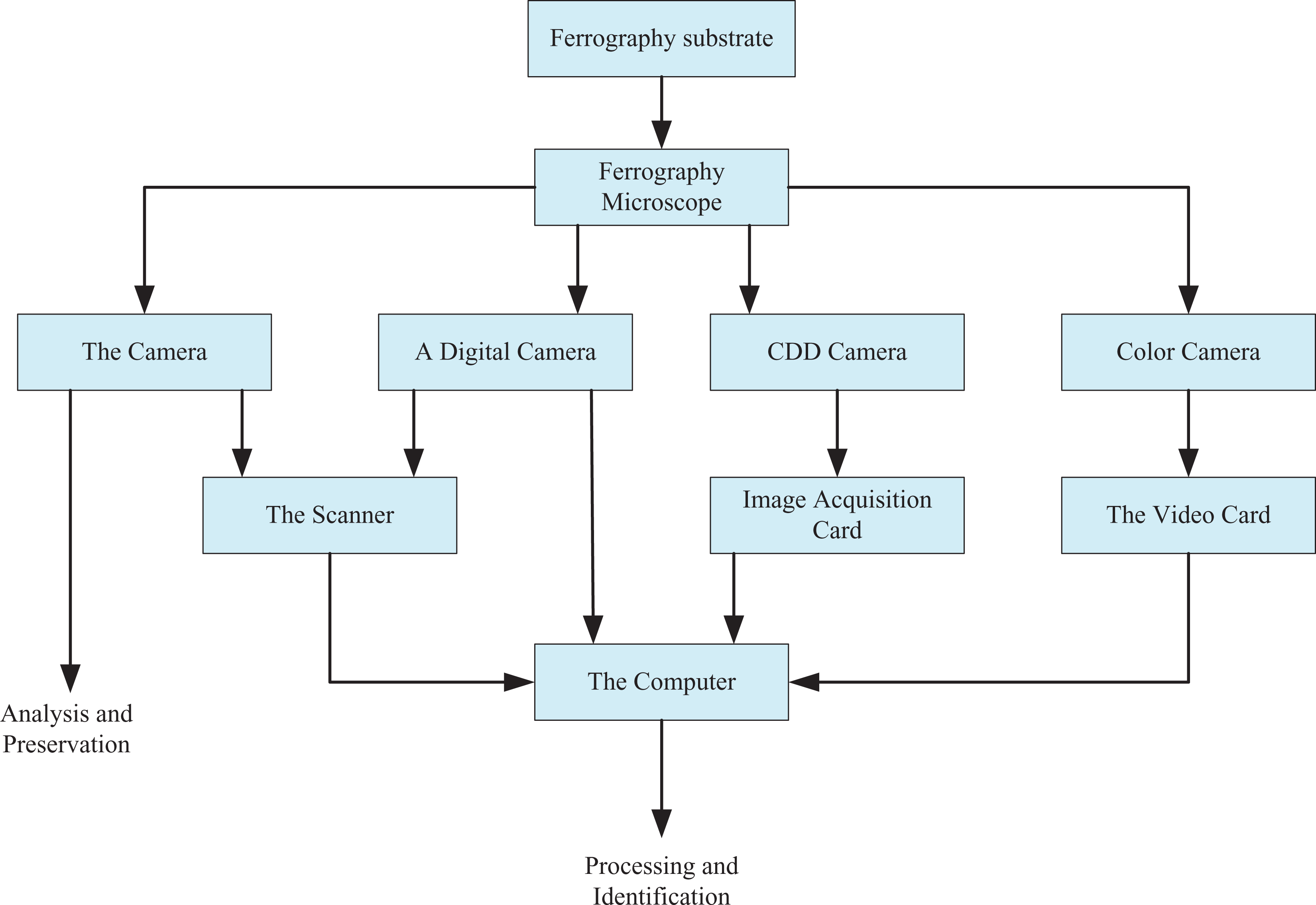
Schematic diagram of image extraction process.
Preprocessing and analysis of abrasive images
Due to the interference of imaging equipment and external environment, grinding-grain images will cause image pollution and lead to image degradation in the process of collection, conversion, and transmission. To reduce the influence of distortion and noise on the abrasive image, the image was preprocessed. Some false abrasive grain edges or contours on the abrasive image are caused by noise, and sometimes some isolated noise points appear on the image are also caused by noise. The image preprocessing can process the above factors, so that the obtained grindstone image is clearer, easier to analyze, and convenient for subsequent feature extraction and grindstone recognition. (1) Grindstone image enhancement analysis
The image is processed by the hard segmentation method such as threshold segmentation, which leads to the distortion of the target information and the noise interference still exists. Image enhancement is carried out to obtain more useful information, which lays a good foundation for the next step of image segmentation. Image noise usually refers to some information that has nothing to do with the image generated in the process of image acquisition, conversion, or transmission. There are many reasons for image noise, such as noisy working environment, high-speed shock vibration of machine tools, or uneven illumination, which have a great impact on image segmentation, and even affect the accuracy of the feature parameters extracted later. Therefore, image denoising is very necessary. Due to the different causes of image noise, the noise generated is also diverse. In this article, the image process is mainly affected by the sensor and uneven illumination, so there is mainly Gaussian noise. Figure 4 shows the gruel image interfered by Gaussian noise.

Image with Gaussian noise.
After careful observation, Gaussian noise appears in the gruel image in the form of black dots, which causes interference to the image segmentation and even makes it impossible to accurately separate the target gruel from the background. In view of this, image enhancement processing is very necessary. Image enhancement processing mainly refers to the suppression and reduction of noise, which is realized by image filtering, that is, smoothing processing. Template operation is the main idea of smooth processing, which is realized by removing a point in the image and the points around it by convolution operation. Although the filter has the ability to remove noise points, it can also make the whole image become fuzzy. To reduce the influence of noise on image quality as much as possible, digital image filtering (also known as smoothing) is the main way to suppress and reduce noise. The basic idea of filtering is to perform the template operation to remove the suddenly changing points through the points in the convolution image and their adjacent points, so as to filter out the noise. However, filtering will not only filter out the noise but also affect the useful information in the image, resulting in some degree of blurring of the image. Since different filtering methods have different effects on images, different filtering methods can be compared and analyzed to minimize the impact on image quality. (2) Processing and analysis of abrasive image filtering
Image enhancement processing is mainly to suppress and reduce the noise, through image filtering, that is, smoothing processing. Template manipulation is the main idea of smoothing. The convolution operation is used to remove a point in the image and the suddenly changing points around it, so as to achieve the purpose of denoising. Although the filter has the ability to remove noise points, it can also make the whole image become fuzzy. To minimize the influence of noise on image quality, digital image filtering (also known as smoothing filtering) is the main method to suppress and reduce noise. The basic idea of filtering is to convolve the points in the image with the adjacent points through template operation to remove the abrupt points, thus filtering out the noise. However, filtering not only removes noise but also affects useful information in the image, making the image become fuzzy to some extent. Since different filtering methods have different effects on images, different filtering methods can be compared and analyzed to minimize the impact on image quality. Here are some common filters:
Median filtering is based on the sorting statistics theory to reduce the noise. Its signal processing technology is nonlinear. When the data with noise are encountered, it is automatically ranked on both sides and replaced by the median of the sequence to achieve the purpose of denoising. The mean filtering is similar to the median filtering principle. The mean filtering is also realized by constructing a template, and all pixel values to be processed in the template can be replaced by the mean value. From this point of view, this processing method is simple and efficient, but it has some disadvantages. For example, the edge points of the abrasive particles will also be averaged, which will make the edges blurred and bring difficulty to subsequent image segmentation. To avoid the disadvantage of image blurring, Gaussian filtering emerges as the times require. The principle of Gaussian filtering is based on all pixel values in the image; through weighted average and according to a certain standard, weight is usually determined by the distance from the pixel to the center point; and the closer to the center point, the greater the weight. Gaussian filtering is mainly used to deal with Gaussian noise. In general, the blur generated by Gaussian noise starts from the center point and has an uncertain fuzzy radius. The rotational symmetry of Gaussian filtering can well solve this problem. This feature of Gaussian filtering makes the weight of the pixel in the image smaller the farther away from the center point, which can remove the Gaussian noise well, and can also deal with the edge of the abrasive particles well, which is not easy to distort. Since the excessive smoothing of the mean filter will lead to image distortion, the median filter can retain the information of the image, but it is mainly suitable for processing the point noise similar to the pepper and salt noise. Therefore, this article adopts the Gaussian filter to process the Gaussian noise. As shown in Figure 5 below, it is the effect diagram of different filtering methods of the image with Gaussian noise (Figure 5(a) shows the grain image with Gaussian noise, Figure 5(b) shows the grain image processed by mean filtering, Figure 5(c) shows the grain image processed by median filtering, and Figure 5(d) shows the grain image processed by Gaussian filtering).
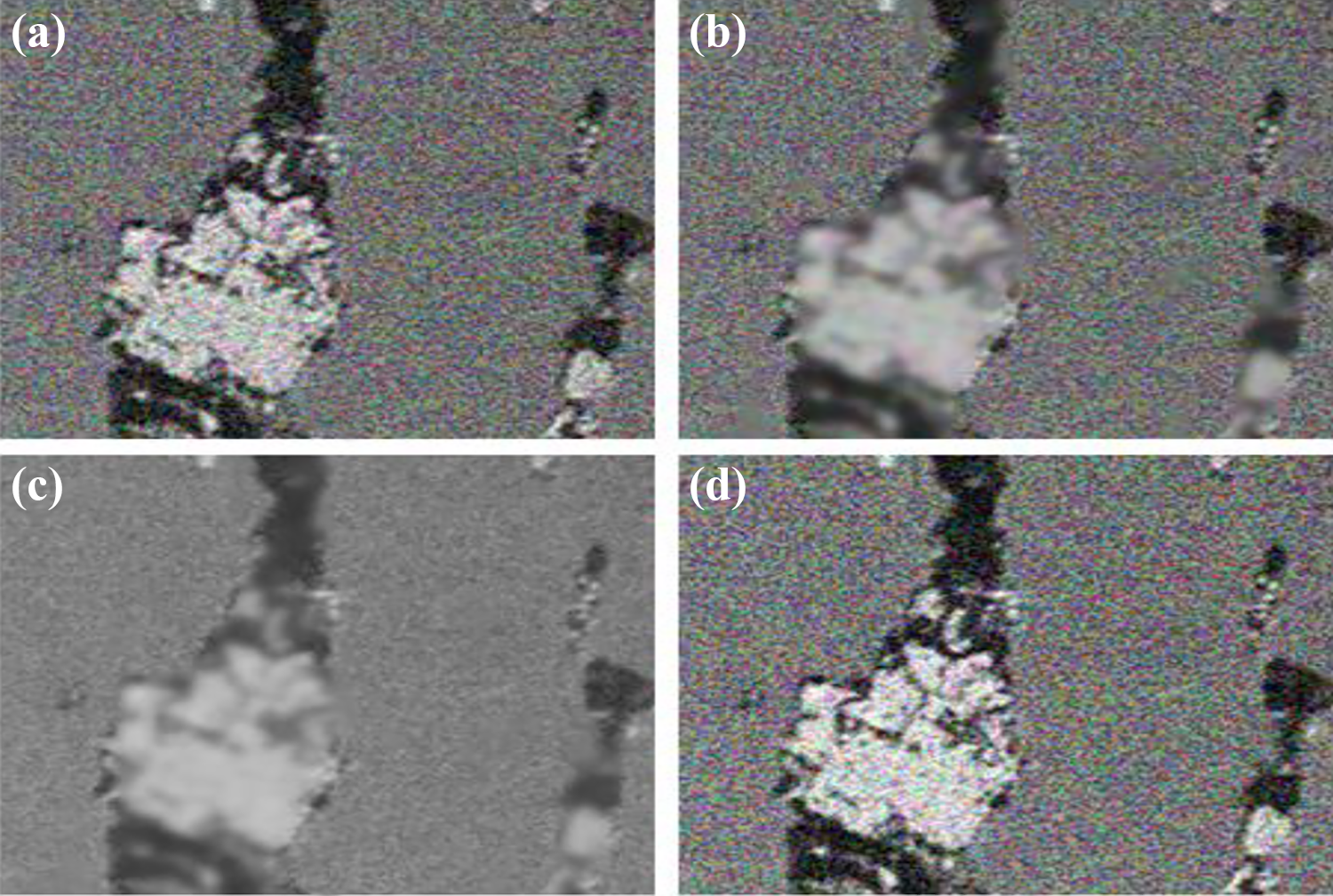
(a to d) The filtering effect of different methods.
It can be seen from the analysis of the picture that the image boundary of the abrasive particles processed by median filtering is blurred, and some small burrs are connected, and the actual shape of the abrasive particles is changed, which will cause inaccurate data extracted from the subsequent characteristics of the abrasive particles, and is not conducive to the research on the recognition of the abrasive particles. The excessive smoothing of the mean filter not only makes the edge of the abrasive particles fuzzy but also leads to serious image distortion. If the mean filter is adopted for processing, the feature value extracted later is far different from the real data, which will lead to the error of feature selection. However, the image processed by Gaussian filtering in Figure 3(d) is not only good at removing Gaussian noise but also has clear abrasive edge and light image distortion, which will not have an important impact on subsequent image processing. From this viewpoint, this article uses Gaussian filter to remove image noise. (3) Image segmentation analysis
The elements in the image have grayscale differences, and the image segmentation is carried out in view of these grayscale differences. The purpose of image segmentation is to extract the target grindstone from the complex background, so as to facilitate the extraction and analysis of the grindstone characteristics. Uniform pixel distribution and similar regions are the main principles of image segmentation. According to this principle, nonoverlapping and continuous target abrasive particles can be segmented, and image segmentation is used to get the goal of grinding-grain quality and will directly influence the accuracy of the subsequent grinding grain of the extraction of characteristic value, which will have interference on the wear particle recognition. In short, the segmentation effect directly affects the recognition of the abrasive grains. Through the comparative analysis of several threshold segmentation methods, this article decided to adopt the maximum category variance method. Gray-level histogram bimodality of gray value is not to control, and the histogram twin peaks method and iteration method are affected by double peak, which does not exist or when double peak is not obvious, the image effect processed by these two methods will be greatly reduced, but the between-cluster variance method is not affected by this, its threshold value can be set up independently, and the processing speed is fast and the operation is simple. The grain-size image segmented by the maximum category variance method is shown in Figure 6 (Figure 6(a) shows the grain-size image and Figure 6(b) shows the processed image).

(a and b) Comparison diagram of binarization effect.
It can be intuitively seen from Figure 6 that the method of variance between the largest categories can accurately realize the binarization of grindstone image, and the processed image has a sharp contrast with the background, so it is helpful to extract various useful information from the grindstone.
Geometric feature extraction and analysis of grinding grains
At present, although there are many researches on the shape characteristics of abrasive particles, there is no unified standard in this respect. About the approximate value range of the shape characteristic parameters of the four types of grinding grains, such as normal grinding grains, cutting grinding grains, sliding grinding grains, and fatigue grinding grains, such as the digitized values of kurtosis, roundness, posture ratio, and slope; the characteristic values such as convexity, girth to area ratio, shape factor, bending degree, posture ratio, roundness, and fiber ratio can be used to describe the boundary of abrasive particles. In short, different types of abrasive particles have different shapes, and the shape characteristics of abrasive particles can be expressed by area, circumference, equivalent diameter, roundness, body ratio, and convexity.
The characteristic parameters of the sphericity of the abrasive particles were closest to 1, and the shape ratio of the abrasive particles was the largest. To eliminate the chance of extracting data, the sample space is expanded; the four kinds of grinding grain of a detailed analysis of the characteristics of the parameters, cutting, and grinding ball mill grain were studied; the characteristic parameters of roundness, aspect ratio, and concavity of cutting and spherical abrasive particles are studied, select 20 pictures of two kinds of typical abrasive particles, extract and analyze the data, and extract the geometric characteristic parameters of abrasive particles. The data of the geometric characteristics of the cutting abrasive particles are arranged into a line graph, as shown in Figure 7. It can be clearly found that the roundness of the cutting abrasive particles is less than 1 and the posture ratio is greater than 1, which can be used as the main feature of identifying the cutting abrasive particles. It can be seen from Figure 8 that the roundness of spherical abrasive particles is close to 1, so roundness is an important characteristic parameter for judging spherical abrasive particles.

Geometric feature curve of cutting abrasive.

Geometric characteristic curve of spherical grinding particles.
Through a series of processing of two typical grindstone images, the target grindstone was separated from the complex background, which laid a good foundation for the recognition of grindstone images in the next step. Through the analysis of the geometry and texture features of the abrasive particles, the parameters representing the geometry and texture features of the abrasive particles, such as area, perimeter, equivalent diameter, roundness, posture ratio, convexity, energy, entropy, correlation, and contrast, were selected to describe the features.
Grain texture feature extraction
From the microscopic image of the abrasive particles, the surface texture of the abrasive particles can be seen. Therefore, the wear mechanism and the type of abrasive particles can be determined by analyzing the texture characteristics. The basis of calculating grain texture feature parameters is texture gray co-occurrence matrix, autocorrelation function, and gray gradient co-occurrence matrix. A scholar extracted the contrast and other texture parameters of seven typical grinding grains and found that the grayscale energy and entropy values of general grinding grains were larger than those of cutting grinding grains, and the texture of normal grinding grains was not significant. The research on texture fractal feature of grindstone image is based on the combination of fractal theory and texture structure feature. Due to the different reasons for the wear of mechanical equipment, the surface texture of the abrasive particles is different. Therefore, the texture feature is taken as another main basis for judging the type of abrasive particles. Generally, the calculation of texture feature parameters is based on autocorrelation function and grayscale co-occurrence matrix, which can be expressed by energy, entropy, correlation, and contrast. Typical grain texture feature parameters are presented in Table 1.
Typical grain texture feature parameters.

From the data in Table 1, it can be seen that the contrast of severe sliding abrasive particles is higher than that of fatigue abrasive particles. As the severe sliding abrasive particles have clear texture and the contrast represents the clarity of the abrasive particles, the severe sliding abrasive particles can be distinguished by contrast. To verify the conjecture, 20 pictures of fatigue abrasive particles and severe sliding abrasive particles were selected for the study. The contrast ratio of severe sliding abrasive particles is generally higher than that of fatigue abrasive particles. Therefore, contrast is an important parameter to distinguish serious sliding abrasive particles from fatigue abrasive particles. Most of the severe sliding abrasive particles are rectangular in shape, and the body ratio is higher than the fatigue abrasive particles, so the fatigue abrasive particles can be identified by combining the contrast and the body ratio.
Mill particle recognition analysis based on support vector machine
The final goal of intelligent identification is to classify the ferromagnetic abrasive particles. After the preprocessing and feature extraction of ferrography images, a single grinding particle becomes a point in the feature space of the grinding particle, and the automatic recognition of grinding particle is the classification of all grinding particles in the feature space. Because support vector machine (SVM) has excellent characteristics in the field of state recognition, such as small sample and global optimal solution, this article carries out the research on SVM in the field of abrasive recognition.
According to the method mentioned above, the characteristics of the grindstone were extracted from the ferrograph image of the diesel engine, and the parameters were optimized. After the data were normalized, the feature vectors of the samples were obtained. To verify the effectiveness of SVM in solving the problem of recognition of feature patterns of abrasive particles, a classifier is designed by using radial basis as a kernel function, and the eigenvector data obtained from the samples are classified and recognized by SVM. In this article, three state characteristics (sliding wear, fatigue wear, and cutting wear) of the abrasive particles are identified for failure. Since there are few fault types, the “one-to-one” identification method is adopted to establish three binary subclassifiers. The first subclassifier, SVM1, is used to identify the two fault states of sliding wear and cutting wear, so as to obtain the optimal classification surface in Figure 9 (the two color crosses in Figure 9 represent different types of faults). The second subclassifier, SVM2, is used to identify the two fault states of sliding wear and fatigue wear, so as to obtain the optimal classification surface, as shown in Figure 10. The third subclassifier, SVM3, is used to identify the two fault states of cutting wear and fatigue wear, and the optimal classification surface, as shown in Figure 11, can be obtained.

The optimal classification surface obtained from classifier 1.

The optimal classification surface obtained by classifier 2.

The optimal classification surface obtained by classifier 3.
As can be seen from the above experimental results, the two types of fault modes are well distributed on both sides of the optimal classification surface, which proves that the SVM has successfully identified the fault types, and the classifier design is also correct. Therefore, it is feasible for SVM to be used for ferrograph grain-grinding fault identification of diesel engines.
Conclusions
In the process of mechanical operation, friction and wear are a very common phenomenon. Friction and wear consume materials and energy and affect the reliability and service life of mechanical equipment. According to statistics, mechanical equipment parts wear is the main reason for mechanical failure and failure, and mechanical equipment parts failure is the main reason for wear, fatigue, and corrosion. Therefore, fault detection and diagnosis has become one of the hot topics in current research. Equipment fault diagnosis technology has developed into a multidisciplinary technology based on fault mechanism, sensor technology, information detection technology, signal analysis technology, pattern recognition technology, computer technology, and artificial intelligence technology. The vision system of the robot obtains color images through the camera for image analysis and processing. The color images collected by the robot camera have different degree of noise, which affects the image quality and further affects the subsequent image processing, resulting in the reduction of recognition accuracy. Therefore, in image visual processing, the image must be de-noised to achieve accurate segmentation, so as to correctly identify targets or obstacles and obtain important position information, which is conducive to further positioning, tracking, and other tasks. Therefore, we should look for an image processing algorithm that can adapt to and overcome the changes in light intensity during image processing. Sometimes image processing needs to meet the real-time task requirements, and visual system design algorithm should also be more concise, less computational. The application of advanced fault diagnosis technology in production can bring great economic benefits to enterprises. Ferrography image recognition technology combines computer graphics image processing technology with ferrography analysis, which has greater objectivity.
The processing method of abrasive image was studied. First, for the gray image processing method, the maximum method, the average method, and the weighted average method are presented. Through comparison, it is found that the image processed by weighted average method is more suitable for human visual effect. Second, it focuses on the enhancement process of grits image, including the noise types in the image and how to reduce the noise. Grits images under different noises were compared with mean filter and median filter, and it was found that mean filter had better suppression effect on Gaussian noise, and the image edge blur was less. Median filter has good effect on noise suppression. Finally, this article studies the edge extraction method of grindstone image. By comparing the effect diagrams of five kinds of operators, it is found that the edge of grindstone extracted by operators is clearer.
Based on wear particle image processing and finishing abrasive goal, although some achievements have been made, but there are still some problems to be solved and improved, in this article, only two kinds of typical wear particles were studied; in the later stage, if increase the type of wear particle recognition, need it increases algorithm on the basis of the optimal classifier model to adapt to more complex particle classification. Due to the limitation of shooting equipment and other conditions, only two-dimensional images of abrasive particles can be obtained. It will be more accurate and the accuracy of the system will be higher if the three-dimensional image of the abrasive particles is used to identify the abrasive particles.
Footnotes
Declaration of conflicting interests
The author(s) declared no potential conflicts of interest with respect to the research, authorship, and/or publication of this article.
Funding
The author(s) disclosed receipt of the following financial support for the research, authorship, and/or publication of this article: This work was financially supported by Ningbo Natural Science Foundation: 2019A610124.