
Abstract
Multisensor data fusion plays a vital role in providing autonomous systems with environmental information crucial for reliable functioning. In this article, we summarize the modular structure of the newly developed and released Common Data Fusion Framework and explain how it is used. Sensor data are registered and fused within the Common Data Fusion Framework to produce comprehensive 3D environment representations and pose estimations. The proposed software components to model this process in a reusable manner are presented through a complete overview of the framework, then the provided data fusion algorithms are listed, and through the case of 3D reconstruction from 2D images, the Common Data Fusion Framework approach is exemplified. The Common Data Fusion Framework has been deployed and tested in various scenarios that include robots performing operations of planetary rover exploration and tracking of orbiting satellites.
Introduction
Recent breakthroughs in machine learning 1,2 illustrate the accelerating pace of research into embedded intelligence and the continued drive for better system autonomy. Space applications in particular require increasingly autonomous systems using multiple sensors to assist the ongoing commercialization of space and maximize the scientific output of future orbital and planetary missions.
Sensory information about itself and its environment is at the root of a robot’s system autonomy. However, it is difficult to reason very far at the raw perception level. Planning complex autonomous behaviors requires a robotic system to have a cognitively higher level of understanding about itself and its environment. Multisensor data fusion meets this requirement: It is the process of aggregating and synthesizing perceptual data, across sensory modalities and across time, into higher level representations of the world and of the robot’s relation to the world.
The InFuse consortium, a partnership of six academic and industrial actors in the European space sector, has developed a modular software architecture for the design, implementation, evaluation, and onboard deployment of multisensor data fusion algorithms. This software architecture is called the Common Data Fusion Framework (CDFF): common because it supports a wide range of sensory modalities and is not specific to any robotic middleware, and framework because it is “a collection of software tools, libraries, and conventions, aiming at simplifying the task of developing software for a complex robotic device.” 3 This framework is designed for the needs of space robotics but can be used in any robotic application domain, but it does have a particular focus on space robotics. Relevance to space has been ensured through the guidance of European Union (EU)-mandated representatives of the European Space Agency (ESA) and several national space agencies. We have released it as free and open-source software (https://gitlab.com/h2020src/og3), with optional proprietary components provided by the french and german space agencies (CNES and DLR) for the usage of follow-up EU-funded consortia.
At the conceptual level, the CDFF implements multisensor data fusion tasks by breaking them down into small atomic data processing tasks organized in a data flow graph, with sensor data flowing in and data fusion products flowing out. At its core, it features a collection of reusable software modules that implement a large number of atomic data processing tasks, each with a software library written in C++ that exposes a common interface and uses Abstract Syntax Notation One (ASN.1) data types. In addition to the atomic modules, we have released a set of complete data fusion pipelines as part of the framework, as examples and for out-of-the-box operation. Finally, the framework is completed by a set of user-facing development and prototyping tools for log replay and visualization written in Python. Integration with robotic frameworks and message-passing middlewares is planned but not yet released.
Our previous papers have described the motivation behind the project, the initial architectural design, the data fusion techniques considered for implementation, the ongoing work on the framework implementation, the orbital and planetary test scenarios considered for evaluation, and finally the first applications of the framework to the problems of stereo reconstruction, environmental mapping, vision-based localization, and visual tracking. In this first publication since the release of the framework, we describe the final architecture, give details on the available stereo reconstruction pipeline, and report on the final evaluation of a visual tracking pipeline in an orbital simulation facility and a vision-based localization pipeline in a planetary analog site.
Related work
Multisensor data fusion
Decades of research in robotics have brought about a large variety of multisensor data fusion algorithms, many of which have been released as programs or libraries of varying quality, reusability, and adoption rate. These algorithms and their implementations offer dynamic state estimation, environmental modeling, or both.
State estimation, for instance, can be achieved at low computational cost using a nonlinear complementary filter 4 or a gradient descent algorithm 5 that fuses together angular velocities, linear accelerations, and optionally magnetic field readings into an orientation estimate: Reference implementations of these methods in C, C#, and MATLAB are available. 6 If using video cameras as the main sensory modality instead, images or image pairs can be fused together across time into an ego-motion estimate by visual odometry: Recent libraries available for that task, each with their own particular focus and strong points, include LIBVISO, 7 fovis, 8 DVO, 9 direct sparse odometry, 10 and semi-direct visual odometry, 11 the latter a proprietary solution contrary to the previous ones.
Environmental modeling can be performed by structure-from-motion and multiview stereo methods that respectively produce sparse and dense 3D point clouds of the environment, which can then be postprocessed into possibly textured 3D models such as object meshes and elevation maps. These methods fuse together images or more usually image pairs across time. Well-known free and open-source software for that task include Bundler 12 (sparse only), CMVS/PMVS2 13 (dense only), VisualSFM 14 (sparse) (proprietary graphical front-end but open-source underlying libraries), OpenMVG 15 (sparse), OpenMVS 16 (dense), MVE 17 (both), and the more recent Theia 18 (sparse) and COLMAP 19 (both). Additionally, other methods of environmental modeling are available for working with depth cameras instead of, or in addition to, video cameras. Volumetric 3D reconstruction based on truncated signed distance functions, for instance, has been implemented a number of times by successors and variants of the seminal KinectFusion method. 20 An open-source example of this approach, optimized for real-time large-scale depth fusion, is InfiniTAM. 21
Finally, multisensor data fusion methods that offer both dynamic state estimation and environmental modeling are of course a staple of robotics. All aforementioned reconstruction methods recover the pose of the sensor relative to the reconstructed model, but the most well-known example is simultaneous localization and mapping (SLAM). ORB-SLAM2, 22 LSD-SLAM, 23 and GTSAM, 24 for instance, are well-known libraries in the realm of visual SLAM, where visual perception is fused with odometry readings or inertial measurements into a map of the environment and the sensor’s position. Other noteworthy libraries include, among others, the recent RGB-D SLAM system ElasticFusion 25 and the 2D and 3D lidar SLAM software Cartographer. 26
These data fusion libraries are always specific to the problem they address: They implement a particular algorithm, or a few related ones, to deal with a particular robotics or computer vision problem. In contrast, the CDFF strives to be wider in scope. It is a modular software architecture where any multisensor data fusion algorithm can be implemented, whether it already exists or is being designed: a common software framework for any kind of data fusion work. In this respect, a close analog is the recently released Sensor Fusion and Tracking Toolbox for MATLAB, 27 which like the CDFF “includes algorithms and tools for the design, simulation, and analysis of systems that fuse data from multiple sensors to maintain position, orientation, and situational awareness.” The toolbox offers orientation and pose estimators, Kalman and particle filters, and multiobject trackers to realize data fusion on simulated sensor data: altitude, GPS, inertial, magnetic, infrared, radar, and sonar. Like the CDFF, this toolbox makes it possible to prototype data fusion pipelines but is proprietary and currently limited to simulated sensor data, whereas the CDFF is open-source, meant for real-time data, and targets onboard deployment.
Robotic frameworks
Given its framework nature and its application domain, the CDFF also appears similar to robotic frameworks such as the robot operating system (ROS) and the robot construction kit (Rock) ROS and Rock, which include their own data fusion features: ROS nodes implementing orientation estimation, 28 visual odometry, 29,30 or SLAM 23,31 have been made from the aforementioned data fusion libraries. ROS is a standard in many application domains, where its simplicity, practicality, and large community are appreciated. In space robotics, every agency develops and uses mission-specific software. NASA developed the CLARAty 32 framework with 44 CLARAty modules which provides software components for a higher level decisional layer and a lower level functional layer. However, publication and development of CLARAty has ended, and the only recent public reports of middleware usage concern several prototype systems using ROS and/or Real-Time Innovations’ commercial middleware for mission critical systems. 33,34
However, those are full data fusion pipelines, whereas the focus of the CDFF is on assembling such pipelines. For this task to be possible with ROS, the components of the pipelines would have to be implemented as ROS nodes, with a data exchange interface based on the publish–subscribe model of the message-passing middleware. While this is perfectly possible, this would make them ROS-specific. Yet designing, assembling, evaluating, and deploying data fusion pipelines is a task which does not have to be ROS-specific. It can, and it should, be abstracted away from the low-level aspects that are the primary focus of ROS—abstracting hardware, handling device control, and providing a message-passing middleware—so that it can be performed in the context of other robotic frameworks. For this reason, we have designed the CDFF to be middleware agnostic. It focuses on data fusion only and leaves out to an unspecified robotic framework the responsibility of passing data between the pipeline components or between the pipelines and the user-facing development tools. The benefit is potential usage of the resulting data fusion framework with any robotics framework, and the disadvantage is that bindings must be written for each robotics framework one wants to use the CDFF with. As we used ROS during our experimental validation of the framework, we have written such an interface to ROS, but it is still experimental, so we have not released it yet.
In Europe, the ESA has been investigating robotics software for mission critical systems too, with the successive projects The Assert Set of Tools for Engineering (TASTE), 35 Space Automation and Robotics General Controller (SARGON), and European Space Robotics Control and Operating System (ESROCOS). 36,37 TASTE is an open-source toolchain for the development of “correct-by-construction” software for embedded, real-time, heterogeneous, mission critical systems. It has a strong focus on formal modeling and on generating safe, optimized Ada and C code from Architecture Analysis and Design Language and ASN.1, two formal description languages. It is the basis of SARGON and ESROCOS, two successive steps toward a space-grade robotic framework for future European missions, including software and hardware modeling tools and communication and formal verification tools. Thanks to its middleware agnosticity, the CDFF could be integrated into ESROCOS, whose consortium worked in parallel and in cooperation to ours. As a matter of fact, to make it easier to integrate both projects, we have used the same TASTE data types as ESROCOS, transcompiled to the same C structures by the same TASTE-provided ASN.1-to-C compiler.
Structure of the CDFF
Data fusion nodes (DFNs), defined as atomic and reusable processing units that perform a single data fusion function, constitute the core of the CDFF. Their atomicity makes them reusable and specialized. Consequently, they need to be connected and coordinated to each other to produce a particular data fusion product. We call a particular arrangement of DFNs, together with the controller that coordinates them, and the local data store (if any) for the data they use or generate, a data fusion processing compound (DFPC). Activation and deactivation of these DFPCs, as well as all other control and data flows within the framework, are the responsibility of an Orchestrator component. Finally, the last component of the framework is a data product manager Data Products Manager (DPM) that stores and retrieves data from persistent memory on request from the Orchestrator. The three main components of CDFF are the DFPCs, the Orchestrator, and the DPM. These components are depicted in Figure 1.

This diagram presents how the three components of CDFF-Support interact and also how the CDFF interfaces with the sensors and autonomy subsystems. CDFF: Common Data Fusion Framework.
The framework consists of three major components, named CDFF-Core, CDFF-Support, and CDFF-Dev. CDFF-Core and CDFF-Support are designed to be deployed in the target robotic system, while CDFF-Dev is intended for software engineering of data fusion software and performance evaluation. The source code of the CDFF that is designed to be deployed on a robotic system is developed in C/C++, while CDFF-Dev is implemented in Python.
CDFF-Core
The CDFF-Core consists of a set of DFNs, each of which performs a specific data processing task commonly part of robotic perception tasks, for instance, feature extraction in an image or Kalman filtering of a system state. They have a minimalist interface consisting of inputs, outputs, a configuration, and a process operation. The implementation of a DFNs can be as simple as a stand-alone C++ class or involve the usage of complex libraries. All DFNs are C++ instances of classes that inherit from a Common Data Fusion Node Interface. An example of a DFN interface is shown in the Code Sample 1. Although in our experiments all DFNs have been deployed as single processes in the target middleware (e.g. ROS), the CDFF does not impose any particular deployment restriction: We consider the deployment view a feature to be covered by the middleware and very dependent of the particular robotic mission’s hardware. DFNs, at the CDFF level, are abstract with respect to this.
Definition of the interface of a DFN. Abstract Syntax Notation One (ASN.1) has been used in the definition of the types.


CDFF-Support
CDFF-Support is a set of more fully fledged DFPCs, assembled by connecting DFNs together into larger software modules that generate specific data fusion products (e.g. pose estimation) from specific sensor data inputs. CDFF-Support also includes two software modules required for the actual execution of these DFPCs on a robotic system: an Orchestrator which coordinates the data fusion processes running on the system and a DPM which maintains the data fusion products pertaining to environment representation during the lifetime of the system.
The DPM stores a consistent representation of the environment, a history of acquired preprocessed sensor data, estimated poses, and a selection of the generated fused data products, to deliver them under request of the planning modules. Data are also stored locally within DFPCs so that it can be further exchanged between DFPCs as well as made available for the central DPM.
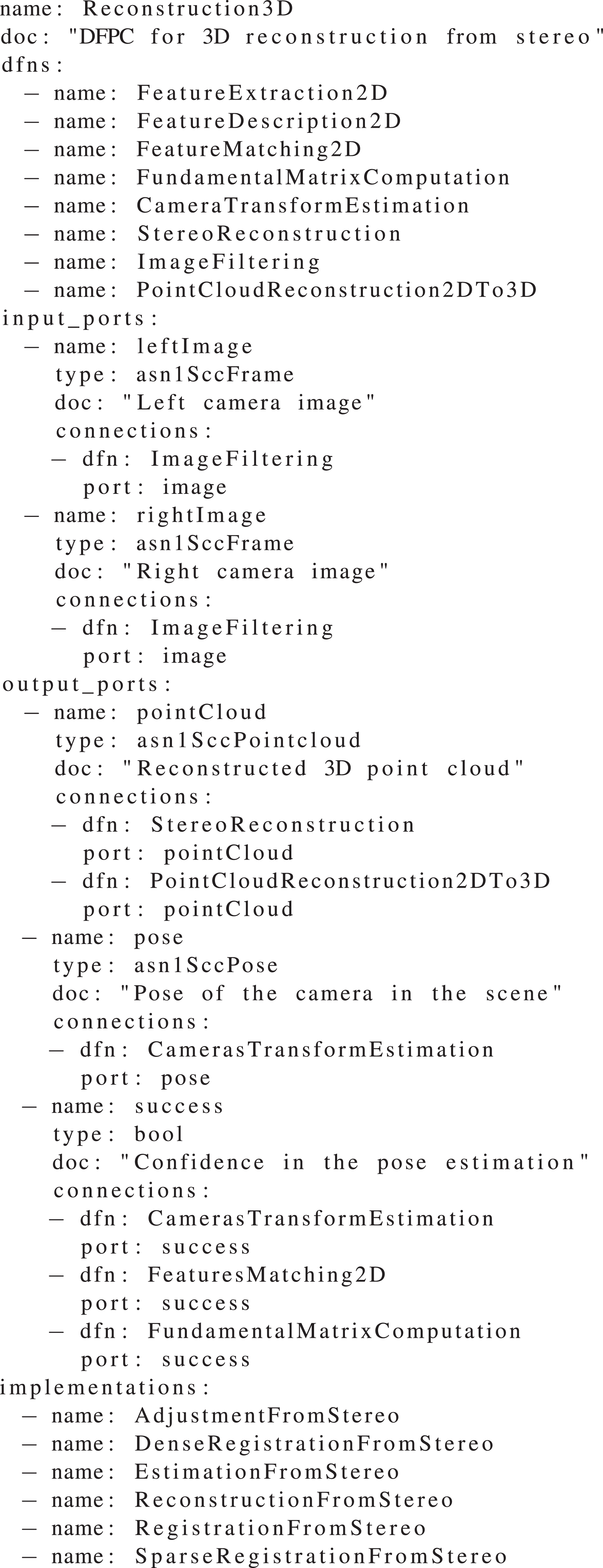
Each DFPC is characterized by its function or functions, the data streams that it receives and produces, including the corresponding metadata (for instance, timestamps and geometric models), the operations that it can execute on demand, the DFNs it uses, and how these are configured and set up. We use description files such as the one in Code Sample 2 to have a clear definition of the functionality of each DFPC. Currently, the DFPCs that are available are presented in Table 1; these DFPCs have been tested on real systems in analog to planetary and orbital missions.
Description of the Reconstruction 3D DFPC. Descriptions are available for each DFPC. The interfaces can be created directly from them.

DFPCs available in the initial release of the CDFF.

CDFF: Common Data Fusion Framework; DFPC: data fusion processing compound.
The Orchestrator has the main task of receiving queries from the onboard planners (deliberative and executive), which consists of symbolic, task, path, and motion planning for planetary rovers and on-orbit servicing satellites. Here the planning component is referred to as the autonomy framework. The Orchestrator is in charge of controlling DFPCs and providing the fused data products to the autonomy framework. It acts as the system integrating component to coordinate the activation states of DFPCs for processing raw or low-level processed data in the target system to control. The Orchestrator has the following functions: (1) interface between the autonomy framework and DFPCs, (2) translate the perception and localization data into the format as requested by the autonomy framework, (3) interface with the sensors’ instrument control unit to configure a limited set of operational modes and sensor-specific parameters, (4) interface with the Data Products Manager (DPM) to provide mechanisms for querying fused data products, and (5) controlling the runtime life cycle of configuring, activation, and deactivation of DFPCs according to autonomy framework requests and corresponding operational modes of the sensors. This last function does not interfere with internal DFPC decision-making processes.
The role of the DPM is to handle the selection, structuring, and storage of all the data processed or produced by the CDFF that may be reused, either internally by the CDFF processes or to satisfy requests from the autonomy modules. Additionally, it is foreseen to become the interface through which robots expose and retrieve the CDFF data products in multirobot scenarios and also the interface through which ground operators can access the CDFF data products. The DPM should become a robotics-dedicated geographic information system. With respect to the activated DFNs and DFPCs in the CDFF, the DPM processes the data insertion requests. Internally, it manages all the spatial-related data by implementing insertion and retrieve functions; deletion operations are not yet implemented, but the back-end libraries support these features, aiming at satisfying future needs for data products and storage constraints.
Figure 2 shows a diagram that summarizes the presented architecture. On a robotic system, multiple DFPCs can be dynamically instantiated by the Orchestrator depending on factors such as the demands from the planning components, the environmental conditions, or the achieved performance. A central data products manager is available to store in, and retrieve from, permanent memory data products that can be requested by other modules or by DFPCs. Internally, each DFPC has a number of interconnected DFNs triggered by a controller which has access to a local memory. Some DFN inputs and outputs are respectively connected, through DFPC interfaces, to sensors and to planning components.

The Orchestrator manages the queries to the central data product manager, the activation of different data fusion processing compounds, and the operating modes of the sensors to fulfill requests from the planning algorithms. DFPC: data fusion processing compound.
CDFF-Dev: Development tools
CDFF-Dev provides software development, performance analysis, and data management tools for implementing and evaluating data fusion algorithms. Contrary to CDFF-Core and CDFF-Support, which are deployed on the robotic system, CDFF-Dev tools are meant to be used in a development environment during implementation and exploitation activities.
The first step to evaluate or implement a DFN or DFPC using CDFF-Dev is to write a DFN or DFPC description file. From these, code generators will produce a scaffold for the actual implementation. This ensures that the code will conform to interface conventions without having to rely on a heavy framework. Furthermore, it allows to analyze DFPCs before they are actually implemented and to check connections of DFNs and DFPCs without running the code.
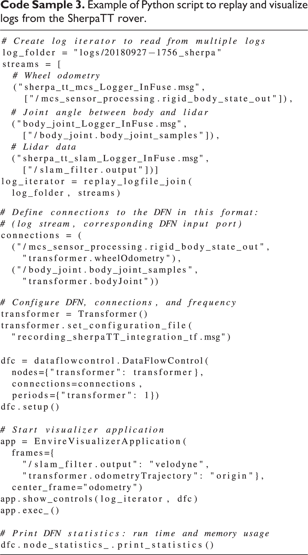
Testing DFNs or DFPCs off-line with log data is possible with the provided Python bindings. Two essential elements are needed for a user to be able to replay data logs from a desired robotic middleware: (1) a conversion from the data log format used by the middleware to an intermediate format that is used by CDFF and (2) a data type conversion from the middleware to CDFF data types. MessagePack is the intermediate log file format that can be handled by CDFF-Dev. Although it is also easily possible to extend CDFF-Dev to support new log formats, log iterators will read log files and stream them to the data flow control. Log iterators can be joined or replayed sequentially. They can handle multiple files and extract only specific data streams from log files. Logs are replayed with a data flow control module that emulates the communication layer of a robotic middleware and a log player that replays logged data chronologically. An example of a replay script is shown in Code Sample 3.
Example of Python script to replay and visualize logs from the SherpaTT rover.

During off-line execution of DFNs and DFPCs, we can store log data and fused data in an EnviRe graph 38 ; hence, we can use the visualizer of EnviRe for 3D visualizations of the data. We can visualize poses, models of robots (in Universal Robot Description Format [URDF]), trajectories, maps, (colored) point clouds, laser scans, and depth maps. An example of a visualized point cloud is shown in Figure 5.

The HCRU engineered by DLR Institute of Robotics and Mechatronics, includes two monochrome cameras, a color camera, lidar, and IMU. In the figure, the device is mounted on the side of DFKI’s SherpaTT robot. HCRU: Handheld Central Rover Unit.
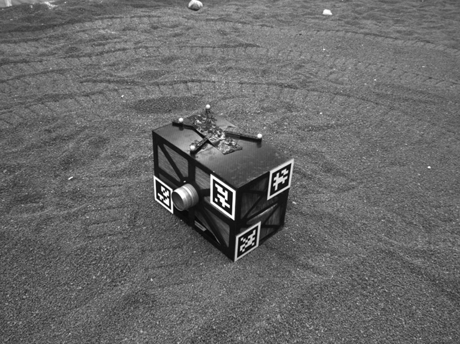
Sample input image from a stereo pair (left camera image) generated in the Planetary Exploration Laboratory of DLR Institute of Robotics and Mechatronics.
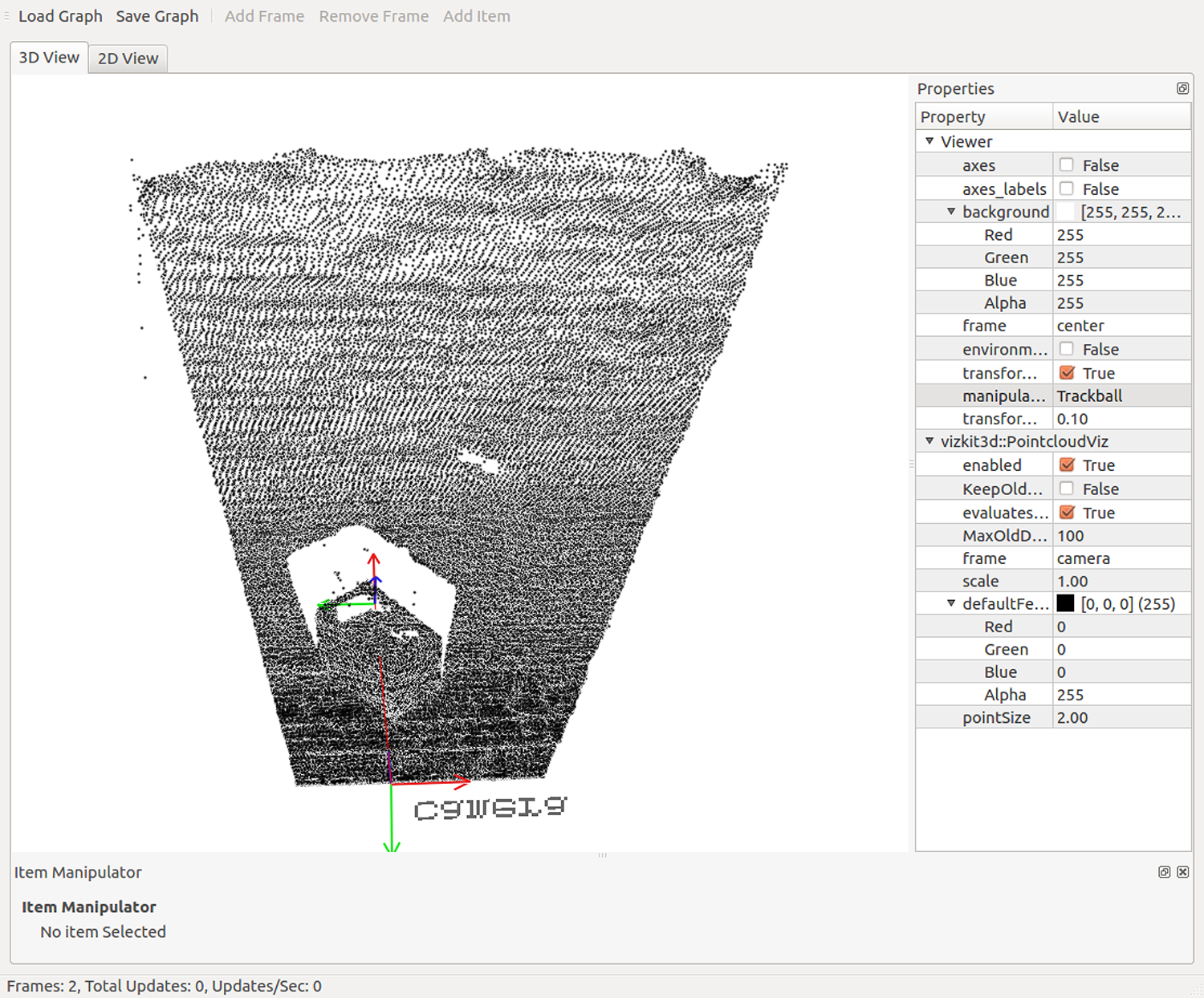
View of a reconstructed point cloud from 10 image pairs in CDFF-Dev’s log replay tool. CDFF: Common Data Fusion Framework.
CDFF-Dev also offers various tools that can be used to analyze log data and configurations. It provides command line tools for log inspection, a visualization of DFPC configurations from DFPC description files, and a simple exporter to comma-separated values files. The latter can be used for easy integration with existing tools from the Python scientific ecosystem, for example, pandas. From pandas, we can easily use the log data for further statistical analysis, visualization, or machine learning in Python. It is also possible to visualize data flow from the data flow control component in a graph, obtain DFN statistics like execution time and memory consumption, or load ground truth maps (digital elevation maps) from GeoTIFF format.
Stereo reconstruction
The most fundamental use of the CDFF is to reconstruct a model of the environment around a robot by fusing data from multiple sensors or multiple samples. For the case of point cloud-based visual fusion, we use a rectified stereo image pair to construct a 3D point cloud by computation of a disparity map as implemented in OpenCV and Point Cloud Library (PCL). The subsequent point cloud is then transformed to the coordinate system of the previous point cloud and fused with it. Two main approaches can compute the pose of each point cloud differently.
Implemented approaches
(1) The first approach focuses on 3D registration of point clouds. 3D features are extracted from a point cloud, descriptors are computed, and from these descriptors we find the transform that allows one set of key points to be overlapped with the other.
(2) The second approach uses 2D feature matching. 2D features are extracted from each image and their descriptors are computed. We then find the matching features between the two images and triangulate the locations of these points in 3D using multiple-view geometry. To track the ego-motion of the camera system, features from the left camera are associated with previous triangulated points in time and filtered based on the fundamental matrix relation. The position of the left camera (and the right camera by extension) is then computed using the OpenCV perspective-n-point solver.
As part of CDFF-Support, we provide three variants of each approach to 3D reconstruction, leading to a total of six different algorithms that can be used within the 3D object reconstruction DFPC. This leverages the modular design of the CDFF to allow a great degree of flexibility in how sensor fusion is implemented in a robotic system.
The first variant of the 3D registration approach works as presented in Table 2 and uses PCL algorithms for feature description and matching. 39 The second variant uses PCL functions and Iterative Closest Point (ICP) on extracted features from the open-source CloudCompare library encapsulated in the Registration3D DFN. The third variant uses ICP on the entire point cloud. The ICP algorithm implementation provided by PCL was found to produce relatively large position errors over very small displacements. After surveying alternate ICP implementations, an ICP algorithm from the open-source libpointmatcher library was implemented and produced good results over large numbers of input images.
The 3D environment reconstruction steps.a

DFPC: data fusion processing compound; DFN: data fusion node.
a The DFNs used for an environment reconstruction DFPC are listed on the left, a typical algorithm used for each DFN is listed on the right. Many different algorithms can be used within a given DFN, and these are known as DFN Implementations.
The first variant of the 2D matching approach works as presented in Table 3. The second variant extends the first variant to improve subsequent pose estimates while satisfying constraints on 3D pose estimate constraints from the projection matrix. In the third variant, both optimization problems are solved numerically using the Ceres library (Table 4).
Final steps of 3D object reconstruction, in the 3D registration approach, for three DFPC variants.
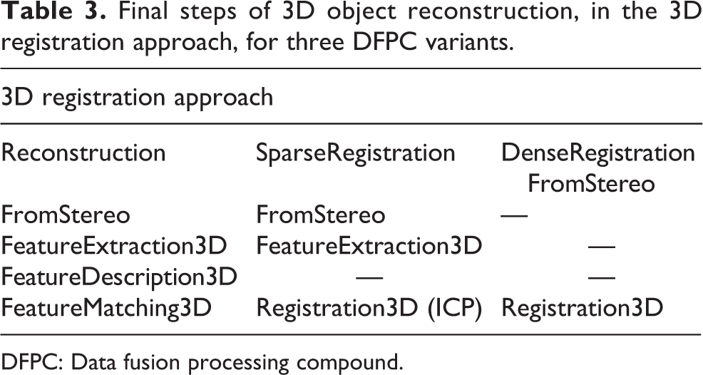
DFPC: Data fusion processing compound.
Optimization steps involved in 3D object reconstruction, in the 2D feature-matching approach, for three DFPC variants.

DFPC: data fusion processing compound.
The two approaches, each with three variants, of 3D reconstruction have been tested on PNG format image sets captured by replaying ROS bag files that were recorded by a mobile computing platform developed for easy handheld operation and easy mounting on mobile robots: the Handheld Central Rover Unit (HCRU) depicted in Figure 3. The bag files were captured in field trials where a mobile robot ran a circular trajectory around a stationary object, capturing one image per second. Figure 4 shows the object in a sample input image, and Figure 5 shows a reconstructed 3D point cloud after 10 image pairs have been processed by the SparseRegistrationFromStereo DFPC.
Figure 5 shows a view of the reconstructed point cloud in CDFF-Dev’s 3D visualizer. Using CDFF-Dev’s tools, the logged data can be replayed, the relevant data given as input to the DFPC, and the resulting data fusion product displayed in an interactive 3D visualization software as the data are replayed. In addition to point clouds, the visualizer tool can also display coordinate frames (two frames, connected by a red line, are visible in Figure 5), trajectories, maps, and meshes loaded from URDF. This data fusion product visualizer, is helpful for developing and examining the results of data fusion solutions (DFPCs).
Choosing the algorithm parameters that lead to the best reconstruction result is difficult because there are many DFNs with many parameters. The main challenge faced was that the complete point cloud is correctly reconstructed only while the error is relatively small. After a certain number of frames, large position errors may break the reconstruction. To prevent this accumulation of error, a DFN named “NeighbourPointAverage” was developed that combines the nearest neighbors in successive point clouds by statistical averaging of position. This DFN proved to work well over large data sets and also proved to be more robust to noise than a simple voxel-based filter, as the voxel filter tended to expand the surface to volumes and the NeighbourPointAverage did not.
Table 5 gives an estimate of processing times and result quality for the environmental reconstruction DFPCs. The best performing DFPCs are SparseRegistrationFromStereo with PCL’s ICP and ReconstructionFromStereo. Dense- and Sparse-RegistrationFromStereo produce similar results, with Dense taking longer. RegistrationFromStereo results in a much larger error, and when using CloudCompare in place of ICP as a registration DFN, a larger error is observed as well. Estimation- and Adjustment-FromStereo have frequently shown poor results too, as bundle adjustment fails to converge in the presence of many outliers. One cause of this may be the small number of poses over which the optimization is run, but this is necessary for robotic navigation in many situations. Failed reconstructions cause the algorithm to skip steps and to complete faster. Hence, some time measurements on full reconstructions are not representative of a complete functional application.
Processing time and reconstruction quality for five image pairs and different DFPC implementations.a

DFPC: data fusion processing compound.
a Times are measured on an Intel Core i7-2770, 8 GB RAM, Ubuntu 16.04 desktop computer.
Evaluation of the stereo reconstruction pipeline
A large amount of data is produced in the many processes contained in the CDFF, especially taking into account the number of DFNs that could be producing data. It is desirable to be able to assess the quality of these data to enable a continuous evaluation of DFNs and DFPCs. We have defined a set of data quality assessment functions to be applied to the vision-based process pipeline composed by extraction and detection, matching, triangulation, and pose estimation, which is used in several DFPCs. Four DFNs used in this process are considered, applied in order for vision processing with their functions clearly indicated by their names: 1. FeatureExtraction2D, 2. FeatureMatching2D, 3. Reconstruction2DTo3D, and 4. PerspectiveNPoint. A set of indicators intrinsically present in the data produced by DFNs is used for this scope. The definition of data quality assessment methods, such as visual feature matchability, enables a continuous evaluation of these algorithms. 40
In feature extraction, the features are ranked by their response value. It is desirable to extract as many matchable features as possible; in fact, any unmatched image feature is discarded in successive steps. We compared the response of features with respect to the features that were matched in the next DFN. This way one could obtain a preliminary idea of the goodness of a feature set and eventually select a subset to feed to the matcher (or even re-extract). While some patterns were found, we found no statistically relevant link between response and matchability. A high response does not imply repeatability. 40 Further in the processing pipeline, we assessed how matching distance could be used for similar goals. Using PnP estimation incorporated in a random sample consensus (RANSAC) scheme benefits large sets of matches (which directly generate 3D points). However, the set of matches surviving the filtering process has to be accurate or will produce too many outliers to handle by RANSAC. We define a data quality assessment function based on the ratio between the sum of distances of accepted matches (i.e., good matches) and the average distance of all the matches. This function (to be ideally minimized) favors large set of accepted matches, still penalizing large average distances. It proved useful as a predictor of poor matching performances. Concerning triangulation, it is possible to propagate the 2D point extraction uncertainty through the triangulation process. This yields the 3D point covariance which directly represents the accuracy of the point cloud. Beder and Steffen 41 show how to estimate the covariance matrix of a 3D point in Euclidean space and proposes a scalar measure based on the matrix singular values to evaluate it. To predict poor estimation by PnP, we used RANSAC inlier percentage levels, which are a direct measure of when the pose estimation cannot be trusted. Low-level inliers, even dropping to zero in some cases, always resulted in a completely off estimation. Having a predictor of reasonable motion estimation is crucial in pose estimation for dead reckoning processes such as visual odometry, where a single large error can compromise the localization accuracy.
Planetary and orbital applications
Vision-based localization of a rover in an unstructured environment
The InFuse CDFF release includes support for external libraries to provide visual localization functions. Two DFPCs for visual localization included: (1) visual stereo SLAM does simultaneously localization and mapping and (2) map-based visual localization uses a previously existing map. Both DFPCs are optimized for space exploration rovers.
Performances are evaluated using metrics described in the study by Kümmerle et al.
42
to provide a statistical analysis of localization accuracy. We use data sets acquired by multiple robots over three campaigns for evaluation in the context of planetary exploration, some of which are planned for release. (1) Indoor experiments done in the DLR Planetary Exploration Lab (PEL): Data acquisition was performed by the ExoMars BB2 prototype rover shown in Figure 7, with the HCRU shown in Figure 3, running the CDFF on board. Ground truth is provided by a tracking system for the full pose of sensors and a custom-made scanner for the digital elevation map (DEM). This smaller setup provides high-accuracy ground truth (error less than 1 mm in position, less than 1° in orientation for poses and less than 4 mm in XYZ for the DEM) and has the ability to easily configure operational parameters such as the slope of the terrain, the number and size of obstacles, and the lighting conditions. It will enable the analysis of fusion algorithms when strong wheel slippage is encountered and incoherent information is then provided by localization subsystems such as wheel odometry and visual odometry.

Relative localization accuracy of CDFF functions when executing a short traverse in the PEL. Top: Visual odometry. Bottom: Visual SLAM. CDFF: Common Data Fusion Framework; PEL: Planetary Exploration Lab.

Test platforms. Top: ExoMars Prototype Rover, DLR’s Institute of Robotics and Mechatronics. Bottom: SherpaTT, DFKI.
Figure 6 illustrates an example of the performance evaluation tests in the PEL. For this test, the ExoMars prototype rover executed a short 12-m trajectory around the facility at a speed of 2 cm/s, acquiring 1032 × 772 stereo images at about 4 Hz. The terrain featured a few obstacles such as bumps, depressions, and small-sized rocks. We can observe that, in this controlled environment and over short ranges, both the visual odometry and visual SLAM perform well, converging to a relative accuracy of 1% of the traveled distance.
(2) Experiments performed in Morocco with SherpaTT: We performed several experiments with the SherpaTT robot, 43 the HCRU as an additional sensor module, and a differential GPS (D-GPS) module for ground truth pose estimation (see Figure 7). Ground truth digital elevation maps with 4 cm resolution are available for the test site. The experiments can be categorized as: (1) long traverse (for localization and mapping), (2) driving around a known object (for 3D reconstruction), and (3) SherpaTT moving in front of an external HCRU (for model-based tracking). We conducted an off-line evaluation of these experiments with CDFF-Dev. We will now describe two experiments and show how CDFF-Dev can be used to analyze the result.
In the first experiment, SherpaTT starts driving at a workshop toward a road to enter the desert. We compare the wheel odometry of SherpaTT with the D-GPS position, which represents ground truth in this experiment. We visualize a simplified model of SherpaTT at the pose estimate derived from wheel odometry, the trajectory of SherpaTT according to wheel odometry and D-GPS, and a ground truth map obtained from a drone. Optionally, we can show the joint movements of SherpaTT. A simple DFN implemented in Python will compare both position estimates and print the error between both to the terminal, but it could also easily be stored or plotted. The visualization is shown in Figure 8. The log files and the GeoTIFF file for the ground truth map have been uploaded to Zenodo (https://zenodo.org/record/2575416). The script can be found in the CDFF-Dev repository (https://gitlab.com/h2020src/og3/cdff_dev/blob/master/examples/morocco/wheel_odometry_with_ground_truth.py).

Wheel odometry (green line) versus ground truth (red line). The map in the background is a digital elevation map captured with a drone. Each color cycle (blue to violet) indicates a height difference of 1 m. The robot model is shown at the current position estimate of the wheel odometry.
In the second experiment, SherpaTT drives in a circle around a box. The stereo cameras of the HCRU are used to make a 3D reconstruction of the environment. The result is shown in Figure 9. The log files have been uploaded to Zenodo (https://zenodo.org/record/2576885). The script can be found in the CDFF repository CDFF-Dev repository(https://gitlab.com/h2020src/og3/cdff_dev/blob/master/examples/morocco/reconstruction3d.py).

3D reconstruction: left camera image and point cloud obtained from 3D reconstruction in EnviRe visualizer.
(3) Experiments performed in Morocco with the Mana and Minnie rovers: A great amount of data was acquired during the test campaign in Morocco with the help of two additional rovers, provided by LAAS-CNRS: Mana, equipped with a lidar, and Minnie, which is focused on visual data, with its three stereo benches. Ground truth data from a RTK-GPS are also provided for both rovers. Acquisitions were performed on three primary sites, each with different terrain features, for example, rocks, sand dunes, large changes in elevation, and so on. The rovers executed various trajectories targeted at common planetary exploration scenarios, such as long traverses (up to 1 km), a traverse followed by a return to base, and rendezvous between two rovers.
The data sets acquired during this campaign were also used for characterization and validation of the performance of a subset of CDFF localization functions, that is, visual odometry and visual SLAM, over very long trajectories and in more demanding operational conditions than what could be tested in the DLR PEL.
As an example, the visual odometry and visual SLAM features were tested on one of the data sets, on which the rover performed a 650-m-long traverse in a mostly flat terrain, at a speed of 30 cm/s. Stereo images with a resolution of 1920 × 1080 pixels were captured at a rate of 2 Hz. Figure 10 illustrates some evaluation results obtained in this scenario.

Relative localization accuracy of CDFF. Top: Visual odometry. Bottom: Visual SLAM functions when executing a 650-m traverse during field trials in Morocco. CDFF: Common Data Fusion Framework.
Visual odometry shows the best performance, as its relative localization error converges to about 2.6% of the traveled distance. It is however clear that the more difficult operational conditions, such as the higher rover velocity, presence of dynamic shadows, and harsher terrain, have a negative impact on localization accuracy when compared to PEL trials and paint a more realistic picture of expected real-world performance. Regarding visual SLAM, relative position error converges to 3.8% on this data set, but reaches up to 6% for shorter travel distances. Analysis of the trajectory allowed us to observe that the SLAM system is especially sensitive to rapid perturbations in rover pitch angle, which results in accumulation of position estimation bias in elevation. These perturbations consist, in the case of this trajectory, in two trench-like obstacles which are crossed by the rover.
On-orbit vision-based tracking of a satellite
The CDFF also includes the model-based visual tracking DFPC which exploits a geometric model of an object to align the image edges, consequently enabling to estimate absolute pose. This DFPC is composed of several DFNs such as Canny edge detection, image filtering, image gradient computation, Kalman prediction, and Kalman correction. The parameters and a geometric model of the visual tracking DFPC can be configured and set in text files, which are in turn used for configuring its DFNs internally.
DLR’s OOS-SIM facility in Figure 11 served as a test platform for validation of the orbital DFPCs. The data sets and ground truth recorded by the sensor suite were relevant for mid-range approach and close-range rendezvous scenarios. The facility consists of a servicer and target satellite mock-ups mounted on large industrial KUKA robots, a lightweight robotic manipulator on the chaser, environment, and lighting to simulate conditions in space. The sensor suite consists of stereo cameras, inertial measurement units (IMUs), and lidar systems.
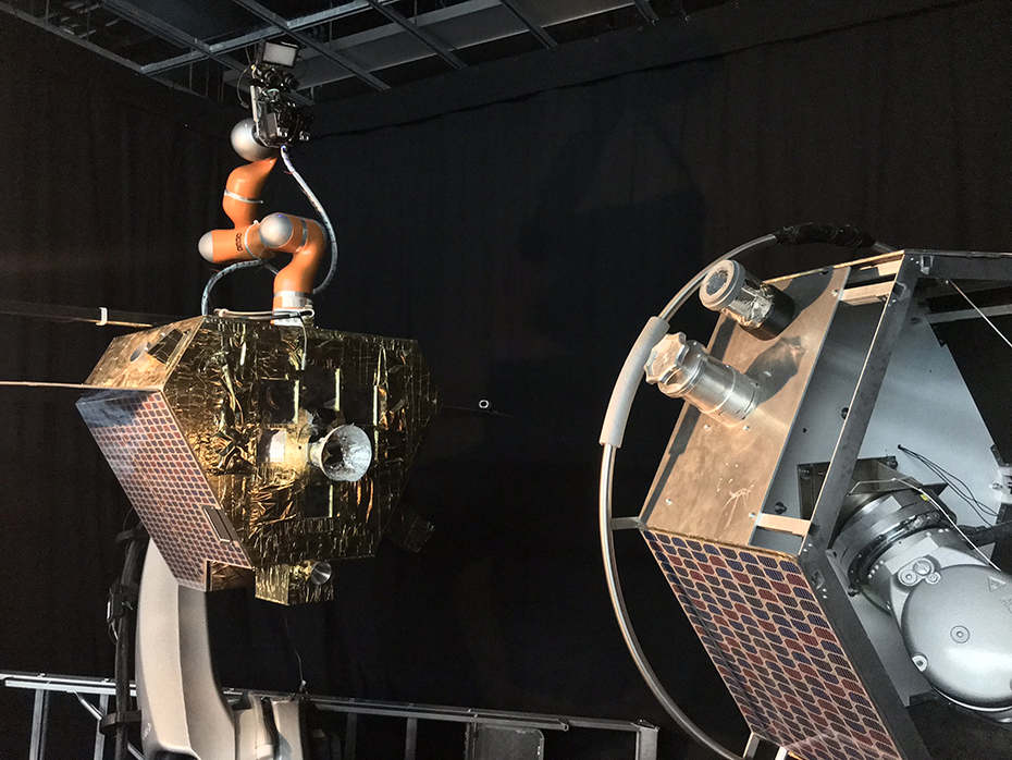
On-orbit simulation (OOS-SIM) facility at DLR.
We demonstrate here a sample pose (image shown in Figure 12, taken from DLR OOS-SIM) where a pose tracking is successful, indicated by the precise alignment of model contours onto the image at the estimated pose. The visual tracking DFPC is a typical InFuse application for an on-orbit satellite servicing. For on-orbit servicing, the target satellite needs to be tracked so that a servicer satellite or robot can autonomously replace parts or refuel it.

Visual tracking DFPC: Alignment of model edges (in red) on image edges indicate correct pose estimation. DFPC: data fusion processing compound.
Discussion
The CDFF is presented as an intermediate software component between libraries from perception and robotic control frameworks. It is independent of the robotic middleware (e.g. ROS) and is not pursuing its replacement. In fact, it is intended to be used as a repository of solutions which can be easily picked up and placed in the target system which might use any robotic middleware. Thus, the use of the CDFF is in principle compatible with any existing robotic framework known to us. In addition to this, it has been designed to allow for the testing of data fusion solutions on sensor data obtained from robots reducing as maximum as much as possible the middleware software overhead. The data fusion implementations provided in the framework have been tested online and off-line.
The CDFF software will be maintained in the following years by researchers and industry consortia in the context of EU-Funded projects which ambitions include the use and enhancement of the framework. Some of the already identified extensions that will be provided in the next years are visual odometry, lidar-based SLAM, absolute localization, DEM generation, pose fusion, coregistration, and moving target suppression. Other already presented features will gain robustness and maturity, like model detection and tracking, point cloud model-based localization, and reconstruction 3D, which will be used in orbital projects, and CDFF-Dev, which will be used in the context of a validation toolset in the ground segment of a planetary navigation project.
Conclusion
The CDFF environment for development, testing, and deployment of perception, localization, and mapping algorithms has been presented. The framework architecture has been designed to produce solutions with highly reusable components: DNFs, DFPCs, Orchestrator, and Data Products Manager. The CDFF provides the first modular open-source framework for fusion of robotic data using a wide variety of algorithms and is specifically focused on providing data products for space robotics both in orbit and on other planets. Among other functions, the CDFF provides data fusion for environmental reconstruction from multiple sensors and views, map generation for navigational learning and reasoning, visual identification and tracking of objects, and localization in both structured and unstructured environments. Furthermore, it allows to describe, implement, and test off-line the software independently of the Robotic Control Operating System that the final robotic system might use. Finally, demonstration scenarios and analysis have been described to illustrate the use and effectiveness of the CDFF in robots for space and also for many other applications.
Footnotes
Declaration of conflicting interests
The author(s) declared no potential conflicts of interest with respect to the research, authorship, and/or publication of this article.
Funding
The author(s) disclosed receipt of the following financial support for the research, authorship, and/or publication of this article: This study was supported by Horizon 2020 Framework Programme.