
Abstract
The spatio-temporal voxel grid is an actively maintained open-source project providing an improved three-dimensional environmental representation that has been garnering increased adoption in large, dynamic, and complex environments. We provide a voxel grid and the Costmap 2-D layer plug-in, Spatio-Temporal Voxel Layer, powered by a real-time sparse occupancy grid with constant time access to voxels which does not scale with the environment’s size. We replace ray-casting with a new clearing technique we dub frustum acceleration that does not assume a static environment and in practice, represents moving environments better. Our method operates at nearly 400% less CPU load on average while processing 9 QVGA resolution depth cameras as compared to the voxel layer. This technique also supports sensors such as three-dimensional laser scanners, radars, and additional modern sensors that were previously unsupported in the available ROS Navigation framework that has become staples in the roboticists’ toolbox. These sensors are becoming more widely used in robotics as sensor prices are driven down and mobile compute capabilities improve. The Spatio-Temporal Voxel Layer was developed in the open with community feedback over its development life cycle and continues to have additional features and capabilities added by the community. As of February 2019, the Spatio-Temporal Voxel Layer is being used on over 600 robots worldwide in warehouses, factories, hospitals, hotels, stores, and libraries. The open-source software can be viewed and installed on its GitHub page at https://github.com/SteveMacenski/spatio_temporal_voxel_layer.
Keywords
Introduction
Modern mobile robotics systems can be complex and challenging to implement from scratch without a deeply knowledgeable and experienced team of researchers and practiced engineers. To build a production grade system, a company needs to draw from experts in path planning, perception, and control and could take years to develop. Today, with the advent of ROS and the associated open-source ecosystem surrounding it, building and deploying production-ready mobile robots is easier than ever. 1
Many tools in the ROS ecosystem are mature, readily available, and documented to make mobile robotics development more straightforward for both subject matter experts and newcomers alike. TF, multiple language clients, and rqt are some of the core tools on top of the ROS message passing platform available under a permissive license. These tools help bring software developers together to collaborate on nontrivial and commonly needed elements of robotics development such as perception, navigation, control, trajectory planning, and more.
The ROS community has built a great deal of software widely available to a typical user. It has changed the way researchers and companies develop autonomous robots. Willow Garage spearheaded the ROS Navigation metapackage (generally referred to as the Navigation stack) for working with its PR2 robot. Willow Garage closed its doors in 2013 and there has been a community effort to maintain and continue developing the Navigation stack (The ROS Navigation stack can be found at https://github.com/ros-planning/navigation.), however without a primary stakeholder to drive forward new initiatives and development, it has largely ceased progress and is primarily being maintained with small feature development. All packages in the Navigation stack trace their roots to Willow Garage and no new packages have been added to it since 2013. However, a number of other packages supporting the Navigation ecosystem have been developed and continued to drive the community forward complementing or replacing elements of the stack based on the needs of the community. 2
Even though many robots in the world today utilize the ROS Navigation framework, critical issues still remain in stack that each need generalized and open-source solutions. Namely, the aging software that makes up the core stack is beginning to deprecate as the state of mobile processors, sensors, and industry are moving forward. Some assumptions made in the creation of the original stack no longer hold in today’s robotics use-cases: a largely static environment where planar simultaneous localization and mapping (SLAM) is adequate for navigation using laser scanners and a single forward-facing depth camera for collision avoidance.
The work presented here is aimed at solving one of these major, long-standing problems: accurately representing dynamic environments. We present Spatio-Temporal Voxel Layer (STVL), a method in the ROS ecosystem for 3-D perception in mobile robots in a highly dynamic environment utilizing an arbitrary number of sensors with the latest and greatest in sensor technologies. The existing method, the voxel layer (VL) has several key issues in the areas above and has not been actively developed since 2014.
In both the spirit of the ROS ecosystem and the intent to open-source STVL for general mobile robot use, this work was developed publicly since its inception. STVL accomplishes the same task as the VL but addresses its shortcomings in the Navigation stack 3-D perception pipeline. It utilizes different data structures, a unique method of maintaining a 3-D occupancy grid we call frustum acceleration, and support for modern sensing technologies. Our method also dramatically decreases the processing load allowing for robots to utilize many high-resolution sensors on a mobile processor in large spaces.
Related work
ROS Navigation
The ROS Navigation stack is a metapackage containing the core elements needed to make a generic robot navigate around an environment. It is often the first place new users go to get a new robot up and running. Many robotics manufacturers will provide ROS-capable drivers and configuration files to make integrating their new robot or sensor into the Navigation stack as seamless as possible. There are a variety of parameters and dials to tune the Navigation stack, supporting primarily omnidirectional and differential drive robots.
This software covers the primary needs for a robot to localize and traverse its environment, with ROS node names in parentheses:
Move Base orchestrates the navigation elements such as the planners, controllers, and perception modules into an action interface to allow the end-user to specify a goal and monitor its progress. A system overview of Move Base and the Navigation stack elements is shown in Figure 1. AMCL localizes the robot based on a particle filter using a 2-D laser scanner’s raw data. The AMCL package is an open-source and widely used implementation of adaptive Monte Carlo localization. 7 Before ROS Melodic, Robot Pose EKF was also included in the stack which was a custom implementation of an Extended Kalman Filter created for the PR2. It is now deprecated in favor of the Robot Localization package, both used to provide dead-reckoning odometry between global localization updates, utilizing odometric and inertial sensors. 1,2,8 Costmap 2-D provides a layered costmap for controllers and planners to compute trajectories and avoid obstacles. The Navfn package implements Dijkstra’s algorithm over the global costmap to compute a valid robot path. DWB Local Planner computes velocity commands for the base to follow a path.

An overview of the ROS Navigation stack. 8
The design of the Navigation stack provides a plug-in interface to allow the end-user to specify or add new software into the stack at run-time without needing to modify the existing code base. As a result, a variety of other planners, controllers, and costmap plug-ins exist implementing a variety of algorithms for specialized use-cases, such as D* lite planner and costmap prohibition layers. 9,10
ROS Navigation perception
The stack’s perception pipeline resides inside of the Costmap 2-D package. This package implements a set of costmaps that can be individually configured as plug-ins and layered together into a larger composite costmap for use in obstacle avoidance and path planning. A few notable layers inside the framework are the obstacle layer and the VL. The obstacle layer implements a 2-D layer which can process the laser scan from a planar laser scanner and place the results into the master grid for navigation. The marked points may be cleared out using Bresenham’s line algorithm while ray-tracing newly marked points from the sensor origin. 11 This plug-in is effective for planar 2-D sensors.
The VL implements a dense 3-D layer which takes in information from 2-D or 3-D sensors such as depth cameras or planar lasers and places them into a regular 3-D grid of a configurable binning size. This layer stores the data in an unsigned 32-bit integer pointer array, the size of the environmental map. The voxel heights are stored by assigning the occupancy bits to the position above the ground, in voxels, the measurement was binned to. Similarly to the obstacle layer, the VL uses a modified version of Bresenham’s line algorithm to clear out voxels in free space. 12
Part of the inefficiency of the VL is a result of the algorithm processing each space in the grid on the ray between the sensor and each voxel to update the environment. This approach carries a computational cost that scales with the distance between a sensor and every voxel. At a maximum ray-tracing distance of d, updating the environment for v depth observations has a worst-case complexity of O(vd). After considering practical physical limits of depth sensors, the maximum ray-tracing distance d can be interpreted as a bounded constant, which would reduce the complexity of the algorithm to O(v).
The voxel implementation has three known issues, which appear often in dynamic environments. First, its modified Bresenham’s voxel clearing algorithm can break down around moving obstacles and leave voxels, which should have been cleared, as occupied resulting in suboptimal navigation behaviors. These phantom voxels often appear as a trail behind moving dynamic obstacles. Two other notable issues include rays not being properly traced when near sensor limits and not clearing obstacles when neighboring unknown space, 13 none of which our approach suffers from. Ray-casting is also a costly operation to run real-time at high resolutions or for long distance sensors. In 2013, the standard robotics depth camera was the Kinect whose high-quality range was below 2 m. The Kinect’s modern day counterpart is the Intel RealSense D435, which can see at three times the resolution up to 10 m away. 14 Moreover, the industry is toward including more sensors around a robot. Benchmarked performance of this implementation can be seen in the “Metrics” section.
Additionally, as the VL plug-in is storing the voxels in 32 bits, there is a fixed height limitation which is unacceptable for large or tall robots or when high resolution is required.
Finally, the plug-in breaks down when processing modern sensors such as radars and 3-D laser scanners. Both radars and 3-D laser scanners have sparse returns or have returns that spread out with distance. The ray-casting algorithms for clearing out free space do not work when there are not dense returns from the sensors, as occupied cells may not be visited even when nearby. Using the VL, the robot will perceive a large number of uncleared virtual-obstacles in its environment.
Other 3-D considerations
General approaches without open-sourced and maintained implementations were not evaluated. To impact the open-source, specifically ROS and robotics navigation ecosystems, a high-quality and maintained implementation must be provided. In recent years, the robotics community has improved on producing open-source samples to accompany paper submissions. However, these releases are frequently abandoned or unmaintained after publication and are therefore not covered in the scope of this article for brevity. Within the ROS Navigation ecosystem, there exists very few potential alternatives to the VL.
The active field of 3-D mapping and localization is filled with reasonable open-source and maintained methods for representing 3-D environments. Some notable and popular examples are Octomap, RTAB-Map, and Google’s Cartographer which can all utilize 3-D point clouds from modern laser scanners and generate a 3-D map. 6,15,16
These methods are capable of representing a 3-D environment but none are particularly suited or written with the intent of use in navigation or collision avoidance in real-time. Octomap is a powerful octree implementation for 3-D mapping and uses the Bayes filter to detect the probability of a cell having an object given a number of sensor measurements. 16 It is possible to build a navigation and collision avoidance framework on top of Octomap’s octree, however many of the powerful utilities Octomap provides are generally unused for a typical navigation task where creating and maintaining a globally consistent 3-D map of the space is not the primary objective. Moreover, Octomap, like the VL, is a dense grid, scaling resource utilization with map size. Within the ROS community, the manipulator framework MoveIt! utilizes Octomap to represent the valid manipulation space to compute trajectories. 17 Some work was started at Willow Garage to use Octomap in a 3-D Navigation metapackage for use in mobile manipulator collision checking that ceased development in 2012. The remaining software is unmaintained and incomplete for basic mobile robot navigation.
Cartographer and RTAB-Map are fully integrated SLAM solutions that produce globally consistent maps of their surroundings. Neither offer direct navigation or collision avoidance capabilities to end-users. Unlike Octomap which is only a mapping solution, it is not advantageous to pull components from a 3-D SLAM solution for use in the navigation. 16 The strengths of these approaches lies in dense reconstruction of the environment at a reduced rate and are used for global localization in the environment, violating the real-time requirements for collision avoidance. These project’s strengths lie in SLAM and while their underlying data storage and retrieval methods have merit, they provide better utility in multi-session and persistent map storage. Cartographer and RTAB-Map use the same approach to data storage. Their approach of storing and accessing data for large maps consists of frequent hard-drive writes, the large amount of disk access may overwhelm the system in practice at collision avoidance update rates. 6,15 Additionally, large amounts of disk access are not ideal for safety critical sub-systems.
In contrast, an in-memory solution like Octomap’s octree is better suited for real-time collision avoidance applications. This is a theme the authors from with STVL. Octomap’s octree has a dense hierarchical data structure that would scale with map size disqualifying its use for real-time mobile processor used in large or virtually unbounded spaces.
Contribution
Overview
Our method is computationally efficient and excels at maintaining an accurate and dynamic regular sparse 3-D environment from a variety of sensors used in modern robotics. This method has been deployed on laptop processors and low power embedded solutions, from a single depth camera to many coupled with 3-D laser scanners and radars. The implementation is a direct drop-in replacement for the VL Costmap 2-D plug-in as the primary 3-D representation of the environment for collision avoidance, path planning, and control.
This approach focuses on technologies that allow for the use of many redundant sensing technologies together in real-time while providing a safely navigable view of the dynamic world.
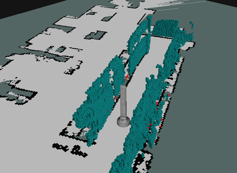
To accomplish this, the concepts of voxel decay and decay acceleration were developed. Voxel decay is used to remove voxels in the environment that do not represent recently viewed measurements. This bounds the computational complexity to the local environment and allows the robot to forget earlier traversed space which may have changed state from moving obstacles such as people, forklifts, cars, and other agents. Decay acceleration is used to thoughtfully maintain an accurate view of the world in view of the robot. By modeling a sensor’s field of view and capabilities, the approach determines the subspace viewable from the sensor’s vantage point, then applies a configurable model to keep or remove an obstacle from the current state of the world. A visualization of our approach can be seen in Figure 2. Voxel decay and decay acceleration are explained in more details in their namesake sections.

A frame of the internal voxel grid being projected over the robot’s environment in a real-world retail environment with a red laser scanner for ground truth.
In support of the methods created, innovations in low-overhead voxel representations are utilized. By taking advantage of a new data structure for robotics use, we can maintain a voxel grid of the environment in a sparse volumetric grid, further described in the “Voxel grid framework” section. This was a key result allowing for this method to be real-time on mobile processors. By combining voxel decay, in-view decay acceleration, and a unique data representation, we are able to deliver a high-performance dynamic environmental model suitable for safe real-time robot navigation.
Design goals
There were several guiding design goals for both the development of the approach and the implementation.
The approach design guidelines can be summarized as: Rich understanding of the 3-D environment Real-time Representing dynamic obstacles with temporal decay Extendable for a future 3-D mapping implementation in dynamic environments Capable of operating in many types of environments, specifically retail, warehouse, and outdoors.
These key goals were defined by the need to better operate in a retail environment and overcome many of the shortcomings of the VL while extending the capabilities available to the community in handling dynamic environments. The implementation had additional requirements. Using the ROS Navigation stack’s Costmap 2-D package as the framework to compare against added a few additional requirements.
The implementation guidelines can be summarized as: Able to handle N sensors real-time, N < 10 Able to support many types of sensors including lidar, radar, sonar, and depth camera Easy integration into the ROS navigation’s Costmap 2-D framework Easy to configure and reconfigure.
Voxel decay
Object permanence greatly enriches the digital representation of the environment, especially when complete observability of the navigable space is impossible. Without modeling recently visited space, robot navigation becomes challenging and requires a great deal of additional sensing capabilities. While many modern robots are beginning to be developed with near total coverage of the surrounding environments, modeling these spaces is necessary to remove oscillatory behavior from partially observable processes in the local time horizon.
However, maintaining an environment based on stale sensor data in previously traversed areas can lead to failures in trajectory planning or a false model of the current state of that area when working in environments occupied by other agents. For the special case of many robots in a space, currently proposed methods of multi-robot coordination and map-keeping can be extended to share a model of the world accurately updating with each agent’s actions. 18 In the more generalized case of operating in environments being modified by other agents, the problem is more challenging. Without additional and robust sensing infrastructure in the environment, it is impossible for a robot to know the exact state of an area out of view.
The goal of voxel decay is to offer a balance between knowing and forgetting the environment. A decay model is used to forget environments that have not been recently visited to receive updated telemetry. If a discretized section of the environment has not been observed in longer than a defined period of time, these sections of the occupancy map are removed. This will bound computational requirements and the voxel grid size by resetting the state of an area that previously had other agents operating within it. Figure 3 shows an example internal occupancy grid visualized with a voxel decay of 15 s as a robot navigates a retail aisle.
A visualization of STVL’s grid with a 15 s decay. STVL: Spatio-Temporal Voxel Layer.
One fault of this approach may arise if a robot does not update maps of the space on a regular basis. If a new piece of infrastructure was installed since the last map was updated, this method will forget the new obstacle and could result in failed optimal trajectory planning. For the purposes of this approach, it is assumed that all pieces of fixed infrastructure are contained in the map used for trajectory planning such that this does not happen. This may be accomplished by updating maps using a lifelong mapping approach, updating regularly, or operating in an environment where large infrastructure changes do not regularly occur.
Decay acceleration
Many existing methods for maintaining environmentally accurate voxel grids employ a ray-casting technique. However, for many modern sensors, this methodology breaks down to support real-time and accurate models of the world around the robot.
New classes of sensors are being used in robotics today, beyond traditional planar laser scanners and short-range depth cameras. Radars, 3-D laser scanners, and long range depth cameras have become inexpensive and widely adopted by robotics applications. These sensors, especially while utilizing many on a single agent, do not allow for real-time or accurate record of the state of moving obstacles.
Radars are being increasingly used to track moving obstacles in an environment. Laser scanners with multiple laser modules spaced apart from manufacturers like Velodyne and Ouster are also gaining popularity. These sensors produce a comparatively sparse set of returns in their fields of view. Ray-casting technologies are adequate for 2-D laser scanners as they produce dense 2-D information. Radars and 3-D laser scanners do not produce dense results to effectively ray-cast away obstacles that have since moved at long ranges. The result is having blotchy occupancy maps to use in trajectory planning representing obstacles that are no longer in that location.
Additionally, 3-D laser scanners and the advent of long range depth cameras field the issue of ray-casting up to 100 m away. This class of sensor yields many highly accurate returns at long ranges, making real-time performance on a standard mobile CPU intractable for just a single sensor. A VLP-16 laser scanner can produce up to 600,000 returns a second at 100 m, equating to up to 1.2 billion voxel queries a second for one sensor while ray-casting. 19 At VGA image quality, an Intel RealSense camera can require nearly 61 million voxel queries for a ray-casting algorithm at a voxel size of 5 cm. This compares to traditional sensors producing QVGA returns at a maximum distance of 2 m, which is 2.5% of the queries of the RealSense. 14
To address the issues with sparse and long range sensors, we propose a new method of sensor marking and clearing in a voxel grid, decay acceleration. Each voxel in the grid contains a time which it was last seen by the sensor. Decay acceleration uses frustum models of the sensors to determine whether a voxel in the voxel grid is viewable from the sensor’s pose. If a voxel is viewable and not seen by the sensor’s returns in that update cycle, an acceleration effect is placed on the voxel’s time using a linear decay model. The linear decay model is
If this voxel is viewable and is seen by the sensor, the voxel’s time is reset to current. For an unviewed voxel, this process will continue in subsequent update cycles until the voxel’s time parameter expires and it is removed from the grid

where

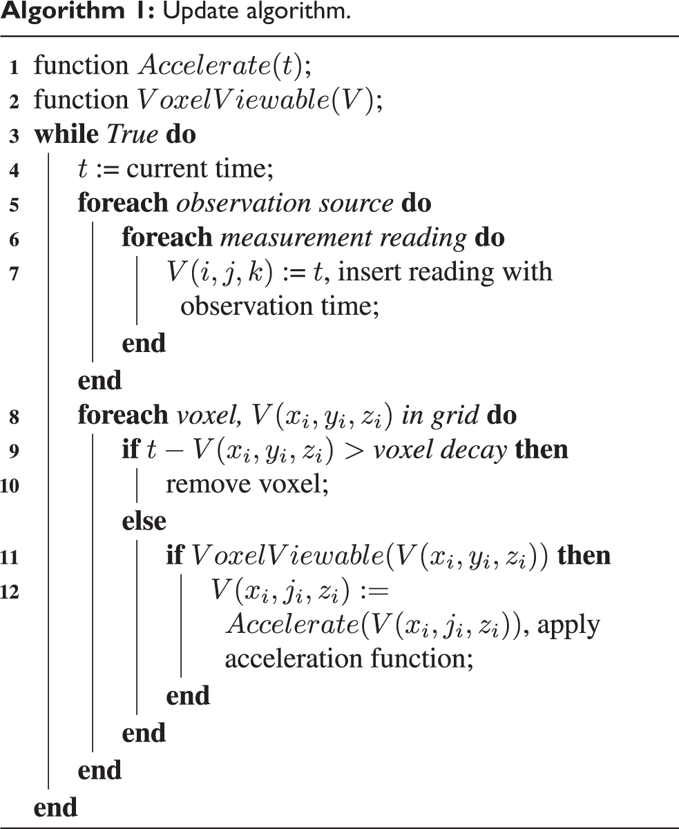
The full STVL algorithm can be seen in Algorithm 1, which consists of inserting measurements into the voxel grid, clearing old voxels from voxel decay, and applying the acceleration model to viewable voxels. Voxels are considered viewable when a sensor can see the voxel in its model, discussed in the “Sensor models” subsection. The provided acceleration model is in equation (1). For robots with redundant sensor coverage, this acceleration has the added effect of more quickly clearing voxels from the grid that have redundant and unviewed coverage by multiple sensors. This phenomenon can be taken advantage of by placing redundant sensors in the direction of travel such that in front of the robot, multiple sensors can view any particular voxel at close range. In this special case, noise or moving obstacles will clear more quickly without artificially increasing the decay acceleration rate.
Update algorithm.

Sensor models
The sensor models are used by the clearing approach to determine whether a given voxel in the current voxel grid is viewable from at least one sensor. Models provided include depth cameras, planar and 3-D laser scanners, sonar, and radar, however more may be used with one of the models provided. Additional models can be easily integrated.
Sensors such as depth cameras, radars, and sonars have a simple geometric representation of a frustum. Their frustums are defined by the field of view of the sensor in the horizontal and vertical dimensions, as well as the minimum and maximum reading distance. These models can be very effectively approximated by six planes representing the field of view angles and valid sensing ranges. The frustum is visualized in Figure 4. Utilizing Algorithm 2, we are able to quickly determine the location of a voxel in relationship to the frustum by analyzing the voxel’s relationship with each of its planes using the point-to-plane signed distance equation. A negative distance indicates the point is on the incorrect side of a given plane to be included in the frustum.

An illustration of depth camera/radar frustum model. 20
An algorithm to determine if a point is inside the six-planed frustum model.


Note: The plane normal computation in Algorithm 2 is cached on startup and used for subsequent cycles. Each update cycle transforms the vectors into the new robot pose.
Sensors such as planar and multi-channel laser scanners do not follow this same frustum model. Their parameters are not field of view and ranges, but measurement elevation, azimuth, and ranges in spherical coordinates centered at the laser scanner’s measurement frame. Instead of checking for the point-to-plane distance to determine if a point is in view of a sensor, the 3-D laser scanner frustum model only needs to check that all the variables are within the valid thresholds for a particular scanner. We can perform the same computation as above for the laser scanner sensor model checking for inclusion inside the window of valid angles and ranges. A demonstration of these parameters is shown in Figure 5, where
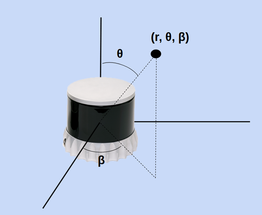
An example of 3-D laser scanner frustum referenced data in spherical coordinates.
Voxel grid framework
For the STVL to represent the environment, there must be a back-end voxel grid implementation to store voxels and allow for fast access.
As a significant proportion of our approach surrounds the requirement of fast voxel access to implement the frustum accelerated decay algorithm, improvements on voxel representations were found. Our approach requires a data structure that enables fast random and sequential access to minimize the overhead from per-voxel computations. Due to the restrictions of obstacle avoidance, it is a priority to ensure complete grid-wide calculations of many sensors in real-time.
Due to the dense regular grid other navigation representations employ, they suffer from a memory footprint growing proportional to volume—creating a bottleneck for maps of large spaces, as shown in Figure 6. Spaces such as retail, warehouse, factory, and outdoor environments are large and would benefit from a sparse grid implementation to reduce resource utilization. We utilized a data structure implemented and maintained by Dreamworks Animations, OpenVDB, built around spatially uniform 3-D grids. OpenVDB implements a data structure resembling B+trees and octrees called Voxel Data Base (VDB).

Sparse volumetric model from the film How to Train Your Dragon with a memory footprint of 1 GB versus 250 GB as a dense volume. 21
Rather than a static branching factor of 2 or N for an N-tree, OpenVDB utilizes an implementation of a hierarchical height balanced octree where the branching factor is only limited to be a power of two, drawing more similarities to B+trees offering benefits of cache coherency, inherent bounding volume acceleration and fast per-branch operations that multi-threading can take advantage of. Additionally, the requirements of animations to support dynamic topology and time-series simulations shares motivating requirements for robot sensors and environmental changes. Furthermore, OpenVDB reduces its memory footprint further by taking advantage of topology-based compression via bit-quantization and other techniques. This approach gives our method constant time access to voxels in the data structure. Moreover, OpenVDB’s sparse volumetric grid’s memory, and access times scale only with active voxels of interest, unlike a dense grid implementation. There is also virtually no limit on the size of the grid, within bit-precision of the signed coordinates. 21 This is necessary for robots operating in massive spaces or unbounded outdoors environments.
The OpenVDB library was created and is used in rendering sparse volumetric grids for feature length films such as How to Train Your Dragon and over 100 others, an example frame is shown in Figure 7. Its intended use is for processing far larger scenes than is practical in current robotics navigation applications, on the order of billions of nodes. The optimizations made in the library, beyond the improvements on the data structure, speed up rendering on supercomputers processing movie frames. These optimizations allow OpenVDB to be used in real-time robotics given the size of navigable space for the local time horizon. Its computational savings compared to the voxel array or octree are significant. Its informed memory architecture directly contribute to caching speedups and memory footprint reductions. 21

An example OpenVDB scene rendered in the film Puss in Boots. 21
Metrics
To assess the performance of STVL, tests were run to measure and compare the resources utilization of the STVL and the VL. A data set of seven depth cameras was collected from a mobile robot traversing a dynamic retail store environment at QVGA quality. The same data set was used for all of the tests. Each test was run using the full duration of the data set. The first and last 30 s of the tests were disregarded in order to take a steady state measurement and sampled once a second. Error bars in the following plots show one standard deviation of the resource measurement results. The tests were run on an Intel i7-7500U processor with 8 GB of RAM available. Comparable configuration files were used for both STVL and VL, utilizing a maximum valid sensor range of 8.0 m from the Intel RealSense D415 and D435 cameras. The two tests investigated the impact of varying numbers of sensors and varying map size on the two methods of 3-D environmental representation.
The first test explored how computational cost was affected by an increasing number of sensor inputs. VL and STVL were run using varying numbers of data streams from the data set, ranging from one to seven. The results of this test can be seen in Figure 8 which shows the effect on CPU usage and Figure 9 which shows the effect on memory usage. With only one sensor input, STVL outperforms VL, utilizing only 11.5% of a core compared to the 18.6% used by VL. For the observed trends, if one core was allocated for perception, VL would be able to process at most 5 sensors, while STVL could process more than 10. Both methods show linear CPU growth, however, STVL scales more modestly with increasing numbers of sensors, utilizing roughly one-fourth of the CPU resources required by VL for the same input. This can be reconciled by the added compute cost of ray-tracing done in the VL which was previously discussed in the “ROS Navigation perception” subsection of “Related Work.” Although Figure 9 shows that STVL has a larger memory footprint than VL, the VL trend shows memory usage increasing roughly two times faster than STVL. While STVL’s memory footprint is consistently higher than VL, for modern computers, both memory footprints are quite reasonable.
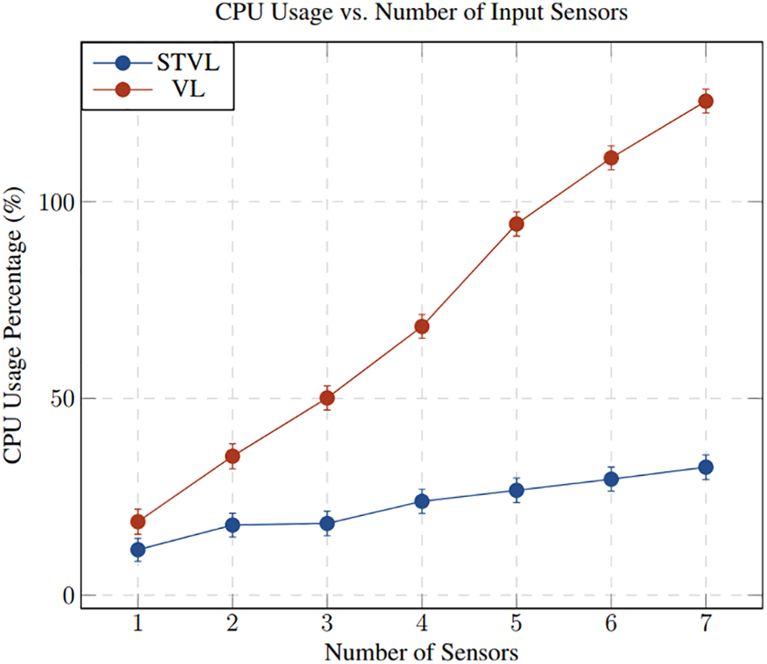
A comparison of the CPU usage of STVL and VL with varying numbers of input sensors. STVL: Spatio-Temporal Voxel Layer; VL: voxel layer.

A comparison of the memory usage of STVL and VL with varying numbers of input sensors. STVL: Spatio-Temporal Voxel Layer; VL: voxel layer.
The second test investigated the effect of increasing map sizes. All seven camera streams were used during this test and only the size of the map was adjusted, varying from 10,000 square feet to 100,000 square feet. Figures 10 and 11 show the CPU usage and memory footprint graphs from these tests. Both STVL and VL show consistent CPU utilization across the spectrum of map sizes, but STVL performs significantly better when considering the memory used for large maps. Since VL has a dense volumetric grid sized the same as the environment, as the map size enlarges, its footprint scales with it. Between 10,000 square feet and 100,000 square feet the memory usage of VL more than doubles while the memory usage of STVL increases by less than 10%. STVL utilizes a sparse representation of the map that is scaled by the number of active voxels, not related to the map size, in line with the trends we see in Figure 11.

A comparison of the CPU usage of STVL and VL with varying map size. STVL: Spatio-Temporal Voxel Layer; VL: voxel layer.

A comparison of the memory usage of STVL and VL with varying map size. STVL: Spatio-Temporal Voxel Layer; VL: voxel layer.
In the case of modern robot architectures, STVL clearly shines with its ability to process many diverse sensor inputs simultaneously at a significantly lower compute cost than VL. Although for small maps, STVL has a larger memory footprint, it scales significantly better than VL with larger maps and requires a relatively small amount of memory when compared to the average resources available on modern computers.
Open-source development
Strategy
Early in the development process, the authors realized the impact of a solution that facilitates operations in large environments with dynamic obstacles. As an element of navigation’s safety-critical perception pipeline, additional users may flush out problems quickly and reduce risk among all users relative to users building their own 3-D perception/costmap replacement. By centralizing development and distributing the risk across more users, software patches and additional capabilities are shared by the user base.
Our strategy was focused on bringing in developers from the mobile robotics community to help architect key elements from the very beginning. The strategy’s implementation focused on making the general community aware of the development effort with the full intent and support to be adaptable for any number of dynamic and static environments.
STVL would also be developed in the open, with issues, tasks, and development discussions happening publicly without restrictions with the aim of attracting collaborators. Another goal of developing in the open was to leave a complete history of discussions, commits, and issues in the public domain that may be referenced in future issues and development, which are typically lost when a project is later released publicly. Much of the development of the original Navigation stack was developed this way. While the vast majority of the software was written by Willow Garage employees or researchers, parts of it continue to be widely used nearly a decade later.
Several tangible initiatives were taken to execute on this strategy: Developing completely in the open from the beginning ROS discourse announcements for major milestones Responding to all community feedback both public and private Encouraging involvement on key features Labeling tickets for outside contributors and future development Presenting at the community developers conference.
Open-source software was heavily leveraged in our method. Some well-known projects provided key capabilities to make it possible: From TBB for parallelization, TF for transforming data, PCL for point cloud operations, boost for threading support, C++’s Standard Template Library for many data structures and utilities, ROS for communication, Costmap 2-D and pluginlib for the direct layer implementation, and OpenVDB for voxel grid storage. 1,21 –23
Open-source metrics
The STVL has received community contributions highlighted in Figure 12 in the 6 months after a large community announcement. The project has received 14 public tickets to add additional capabilities or reporting regressions introduced. Of the nine issues filed, eight have resulted in community contributions. Some of the contributions also implement features marked by the maintainers asking for public assistance.

Overview of community engagement after the first 6 months.
Several new capabilities are available from community contributions. This includes core features such as supporting 3-D laser scanners such as the Velodyne VLP-16 and a general sensor model for lasers to support any number of other laser solutions. This complemented the depth camera and radar frustum models already implemented to support a wide variety of modern sensors previously neglected by other solutions. This opens the door for modern autonomous robots utilizing sensors such as radars and 3-D laser scanners to operate seamlessly in the available open-source ROS Navigation ecosystem. As the prices of 3-D lasers continues to drop, an increasing number of robots will include 3-D lasers in their perception packages.
Additionally, a user implemented dynamic reconfigure support for tuning the parameters of STVL and toggling features while in operation. This contribution will streamline future users’ setup process and implemented a new capability to disable individual sensor streams in real-time. Dynamic reconfigure support will cut the time drastically to tune in-situ and store those parameters for the future. Additionally, support for disabling sensor streams in real-time can allow a user to turn off a defective sensor when a fault is detected.
Other contributions include minor patches and CMake optimizations, including reoccurring support to develop and maintain the latest ROS distributions. Some of these new features come from tickets asking for collaboration and others are innovative capabilities for domain specific uses that have community value.
The project is hosted on the popular Git client, GitHub, which provides some information which may be analyzed. Figure 13 shows a two week period of Git statistics by outside users. Four months of data were analyzed and found that typically there are 63 unique clones a week and hundreds of views ranging from 272 to 612. Figure 14 demonstrates the community interest since the project’s creation. Relevant events to our open-source strategy are highlighted. An increase in interest was seen after both the beta release announcement and ROSCon session that continues to increase after September, 2018. Of the stargazers, 51% were found to be roboticists or technologists in industry and 40% were academic researchers or students (Figure 12).

An example 2 week period of anonymized community clones and views.

GitHub stargazers versus time from February 2018 to December 2018.
Estimating traction of this project in the open-source community is challenging. The main software deployment mechanism on robots is typically Docker containers which may be distributed thousands of times or installing via the available Linux package manager. Neither of these methods provide data about the number of downloads or installs to accurately estimate the number of robots utilizing STVL as their 3-D perception plug-in. There are 260 known robots utilizing it today with an estimated total in excess of 600 robots in circulation world-wide. This represents researchers in academia, small robotics companies, and large companies scaling robot assets. We have the confirmation that our project is being used in retail stores, warehouses, libraries, hotels, and hospitals on at least three continents. Within the retail environment alone, this method has accumulated over 50,000 h of safe navigation.
A revised strategy
While this work represents an improvement in the ROS Navigation perception framework in computation, dynamic obstacle representation, and more, the proposed open-source strategy to garner collaboration did not perform as well as expected in early development.
During the early phases, there was very little direct community engagement. Early posts on community forums helped highlight the project, however they did not result in any issues or further discussions from the broader community. More significant feedback and involvement was seen after the beta release in March, 2018, indicating the robotics community’s demonstrated interest in working with projects further down the development life cycle. The majority of significant contributions were submitted for review after the developer’s conference session advocating its use and a description of the method in September, 2018 (see Figure 14). 24
The maintainers saw a jump in user interest, filed tickets, pull requests, and groups tracking process after September 2018. Feedback from developers and researchers have resulted in several additional capabilities for the project not previously scheduled. Speaking with developers about a full-featured solution in person was a far better method for advocating collaboration and engagement than any other method. While the community online communications gained some traction, it pales in comparison to speaking with a wide audience of community members. From this presentation, several more groups have actively engaged in the development and maintenance of STVL.
The revised strategy is as follows, primarily pushing conferences and developer’s forums earlier in the publicizing efforts: Developing complete in the open from the beginning Community announcements with a detailed call for collaboration Community announcements and developer’s conference session on the first beta prototype Actively gathering community feedback Labeling tickets for outside contributors and future development Continue to engage collaborators to support their features.
Conclusion
In this article, we introduced the STVL and spatio-temporal voxel grid, an open-source method for 3-D perception for use in navigating in large or highly dynamic environments. Our approach uses an efficient sparse volumetric grid to maintain a 3-D occupancy grid of virtually infinite size. STVL also introduces the new concepts of voxel decay and decay acceleration as an alternative to ray-casting-based perception solutions that is better suited for dynamic, human-filled environments. We evaluated our approach against the VL, the widely used voxel grid for 3-D perception and navigation in the ROS Navigation ecosystem. Our method utilizes far less CPU with any number of sensors and has a near-flat CPU usage trend relative to environment size. Our method provides support for most classes of modern robotics sensors including 3-D laser scanners, depth cameras, radars, and sonars.
STVL has gained traction among both the academic and industrial community in the past year since its inception and has been used to power an estimated 600 robots world-wide. The open-source implementation has had great community support and continues to have new capabilities added. It can support generic robot types and support large number of sensors in parallel. It is the authors’ hope that STVL will grow to be the defacto 3-D perception plug-in in the ROS Navigation ecosystem.
Footnotes
Declaration of conflicting interests
Funding
The author(s) received no financial support for the research, authorship, and/or publication of this article.