
Abstract
The issues of chassis dynamics-based navigation sensor fault and state estimation in land vehicles are specialized in this study. Owing to the essential attributes of robust theory-based observers, an H-infinity adaptive observer is proposed to implement the fault reconstructions of faulty sensors, offering a reference to vehicles for further favorable control decision-making. This observer fuses a linear matrix inequality convex optimization strategy, with the dynamics of land vehicles established mathematically, the consequent problems associated with augmented descriptor system state-space model, Lyapunov stability and linear matrix inequality convex optimization are discussed in detail. The numerical simulations on vehicular systems that suffered with single-existing deadlocking, gain scheduling, and constant deflection sensor fault are conducted. The results indicate, the fault channel outputs fairly reflect the variations of real faults under severe step-type fault input circumstances, so that the applicability of the fault observer against sensor failures is guaranteed. The proposed sensor fault construction idea is further extended to a loosely coupled inertial measurement units/global positioning system (GPS) illustration with GPS unavailable in its north velocity channel. After reconstructing the priori system state for “State one-step prediction” of Kalman filter, the compensated navigation parameters by state estimator exhibit consistent with the references as expected, the vehicle chassis dynamics-based sensor fault construction method, therefore, may be recognized as an effective measure to a class of integrated navigation systems experiencing some unknown sensor failures.
Keywords
Introduction
Reliable navigating and positioning capacities are principal attributes of autonomous vehicles. Admittedly, inertial measurement units (IMUs) with six degrees of freedom (DOF) can provide the vehicles with orthogonal three-axial position, velocity, and attitude. 1 However, in cases where no other navigation sensors are present, the measured navigation parameters, especially the measured position error will increase dramatically with time due to the large drafts of IMUs. 2 –5 The integrated navigation systems which fuse external sensors like GPS, Doppler radar, and so on with IMUs can limit the increasing accumulative error. Since GPS allows for vehicles to have access to an absolute external location reference acquisition, 6 by contrast, IMUs/GPS (normally termed as INS/GPS) is generally to be preferred to other integrated navigation systems and is valid for practical vehicular applications. 7,8
When a vehicle is in motion relative to some “fixed” frame of reference, we can obtain a series of moving or accelerating dynamical information, where appropriate, if we could embed this in IMUs/GPS (sometimes IMUs only when GPS deteriorates) information channel to correct the estimated error of navigation states, the vehicle might estimate its own location by suitably utilizing the complete dynamical models rather than burden its body with other external sensors. 9
Robust solutions to navigation information processing associated with the chassis dynamics were firstly employed in aerocraft applications. Since the dynamical models of aerocrafts can fairly describe the relationships between acceleration, angular velocity, linear velocity, and wind speed, nearly all of the early researches concentrate on how to enhance the instrumental performances and evaluate the kinetic parameters of aerocrafts by means of relative dynamical models. 10,11 In recent years, vehicle chassis model aided inertial navigation is increasingly applied to land vehicular navigation circumstances. 12 –14 When GPS (or IMUs) experiences unknown failures, solutions by means of adaptive observations with respect to sensor faults are possible to supply a reference for control decision-making, the control performances and safety of land vehicles are accordingly guaranteed.
When it comes to the issue of observer design, the applicable dynamical models of land vehicles should be firstly concerned. Academically, the observers may take many forms, depending, for example, on modern control principle or disturbance estimation theory. But for the purpose of fault reconstruction applications, three idealized forms are recognized, these are robust adaptive observers, descriptor observers, and sliding mode-based observers.
Robust adaptive methods form the basis of sensor fault observer designs, when combined with other advanced control-based strategies, the robust adaptive type fused tools are generally to be preferred to robust adaptive methods themselves. Descriptor observers address the fault reconstruction problems by extending the system state dimensions, consequently, the fault information estimate, together with the external disturbance input and the actual state of original system will be obtained based upon the reconstructed models. The principal importance of sliding mode-based observer for fault reconstruction lies in its (more precisely, the flow pattern designed is) conductive to the convergence of state estimation error and fault reconstruction error. Meanwhile, it is essentially easy to perform with merits of strong robustness. 15
Yan and Edwards 16 aim to conduct a class of sliding mode observer-based robust fault diagnosis research and has been tested to be valid for a robotic arm system. However, this approach is restricted to known fault upper bound with existing error boundary, meanwhile, the undesired threshold setting would lead to poor fault diagnosis results. Zhang et al. 17 permit the fault diagnosis of robotic arms to be available by incorporating H-infinity theory and adaptive descriptor idea. The related research has been conducted with chief reference to the studies of Lyapunov stability-based H-infinity performance analysis and bilinear matrix inequality (BMI)-based gain matrix estimation. By contrast, even though the proposed observer is not limited to strict error boundary restrictions, it appears to be inapplicable when disturbance and fault co-exist, nor can it locate the faults.
Rath et al. 18 and Qiu et al. 19 are mainly concerned with the adaptabilities of robust controller for sensor fault diagnosis of a class of vehicle chassis dynamics-based systems. An H-infinity controller in generalized internal model control architecture is proved to be adaptable to an active suspension system (ASS) in finite-frequency domain. Qiu et al. 19 guarantees the stability of vehicle ASS with sensor faults by means of higher order terminal sliding mode approach, however, the introduction of high value of the observer gain brings some significant design complexities (leads to peaking phenomena or high chattering for sliding mode) and need to be corrected if favorable control performances were desired.
As in Zhang et al., 17 the development and maturation of above theories opens the door to apply the fused tools to sensor fault observer designs. We conduct and further determine our observer design in terms of the following comparative analyses.
Differing from the observer in Zhang et al.,
17
we explicitly fuse the H-infinity control theory and LMI (abbreviates “linear matrix inequality”) method. The proposed H-infinity adaptive observer appears to be more readily adaptable to situations of coexistence between disturbance and fault, and is available for the solution to fault locations. As a consequence of explicitly taking into account the nonlinear phenomena, the proposed observer characterized by fully considering coexistence treatments of nonlinearity, disturbance and unknown faults dramatically enables its adaptability to a wide range of practical vehicular applications. Specifically, compared with Rath et al.,
18
the sensor fault in our framework would no need to be known, and the estimation of system performance index (expressed in adaptive observer model) could be simultaneously incorporated in the process.
Following the above lines of thought, research on vehicle chassis dynamics-based navigation information estimation and robust control is conducted in this article. With known vertical and lateral dynamics of land vehicles, the proposed H-infinity adaptive observer with convex optimization strategy and augmented descriptor model is expected to eliminate the influences of disturbances over state estimations and sensor fault reconstructions. As a consequence of the fused control scheme, the fault information of navigation sensors used for feed forward compensation of observers would be achieved, which, then helps to correct the state model of Kalman filter for IMUs/GPS parameter estimations.
The main contributions to this paper are shown in the following three aspects.
First, with the hypothesis of small steering angel, the lateral dynamics of vehicles are linearly approximated and simplified. Together with the simultaneously described small road excitation model, the fully established vertical dynamics of vehicles and the incorporated parameter settings of vehicle active suspensions, the general multi-degree of freedom (MDOF) based dynamics of land vehicles are developed.
Second, considering the chassis dynamics-fused navigation information processing strategies for vehicles with no external location reference, the sensor fault reconstruction ideas led to the enhanced H-infinity adaptive observer design, which is not restricted to known fault type or no-disturbance circumstances, being more general in that it applies to non-linear systems with unknown and polluted faults.
Third, as a specific navigation application, the designed H-infinity observer is numerically evaluated via a typical loosely coupled IMUs/GPS, and it is demonstrated that the navigation parameter estimates remain optimal even though a deadlocking took place in GPS north velocity channel. The proposed H-infinity observer design, therefore, can be recognized as a preferred tool reference for a class of land vehicle application domains preceded by no external location reference support hypothesis.
The outline of the remainder of the article is as follows. In the “Relative dynamical models” section, ① the dynamical models of vehicle active suspension, which includes the vertical dynamics and lateral dynamics, ② the random road excitation model, and ③ the fault model of navigation sensors are elaborately described. Due to the multiplicative and additive faults of navigation sensors, H-infinity adaptive observer based on LMI convex optimization is designed in the following section, with H-infinity performance has been derived on basis of Lyapunov stability, the unknown gain matrices of this observer are tested to be solvable and further evaluated. The “Numerical simulations” section carries out the numerical simulations in land vehicles that suffered with deadlocking, gain scheduling, and constant deflection faults. The designed H-infinity adaptive observer is proved to possess superior fault estimation performances regardless of the severe step-type fault input circumstances. Whose sensor fault reconstruction application in loosely coupled IMUs/GPS is conducted in the “The application of H-infinity observer-based sensor fault reconstruction in IMUs/GPS” section, we consequently achieve the main conclusion of this investigation.
Relative dynamical models
For the dynamics of land vehicles, let’s consider a complex MDOF vibration system. Basically, the established dynamical models are intended to reflect the actual behaviors of concerned vehicles under certain operating conditions, which are inseparably related to the model complexity, the body mechanics, and the computational accuracy and work for parameter estimations. The vertical dynamical model should be firstly concerned, the essential part of which is suspension system. In contrast, the lateral dynamics concern the lateral motion and the yaw estimation, whose model may be simplified and whose schematic may be drawn on a plane. In addition, the correlative analyses on the road model should concentrate on the random signals as impinge upon 4 wheels through which they flow, whose characteristics are bound to the external rough road excitation.
Vertical dynamics of vehicles
Vertical dynamics of vehicles are closely related to suspension systems. As a complex mechanical device, the suspension system is constructed of a series of flexible components, like bushing, anti-roll bar, and so on. With simplified model it is relatively performable to achieve reconstruction formula derivation that yields typical motions. The diagrammatic representation of ASS anatomy with vertical, roll and pitch motions of sprung mass is given in Figure 1.

Vertical dynamics of vehicles.
As indicated,

where
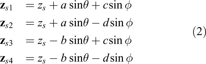
where, zs
denotes the vertical displacement relative to the center of gravity (CG) of the sprung mass. a and b denote the vertical distances between front/rear wheel and center of vehicle; c and d denote the lateral distances between front/rear wheel and center of vehicle.
The nonlinearities of suspension system are expressed as 18

where
Under the hypothesis of small spring deformation, the nonlinear spring force


where ki and bi are related nonlinear coefficients of the ith spring and damper.
Let Fz
,

Consider the coupling influences on the vehicle, the vertical dynamics can be expressed as 20

where ms
denotes the total mass of unsprung components.

where
Lateral dynamics of vehicles
The lateral dynamics of vehicles mainly reflect the correlation between steering input and ① lateral acceleration, ② sideslip angle, ③ yaw rate, a term that takes all of these three factors into consideration is the lateral stability indicator. Given certain conditions, assume that the sideslip angle of vehicle is relatively small, so that it’s provable that the longitudinal velocity at the CG of vehicle is constant. Since we are generally concerned with vertical and lateral dynamics rather than longitudinal dynamics, the established lateral model therefore can be drawn on a plane, as shown in Figure 2.

Lateral dynamics of vehicles.
As in Figure 2, the definitions of

where m denotes the total mass of the vehicle.
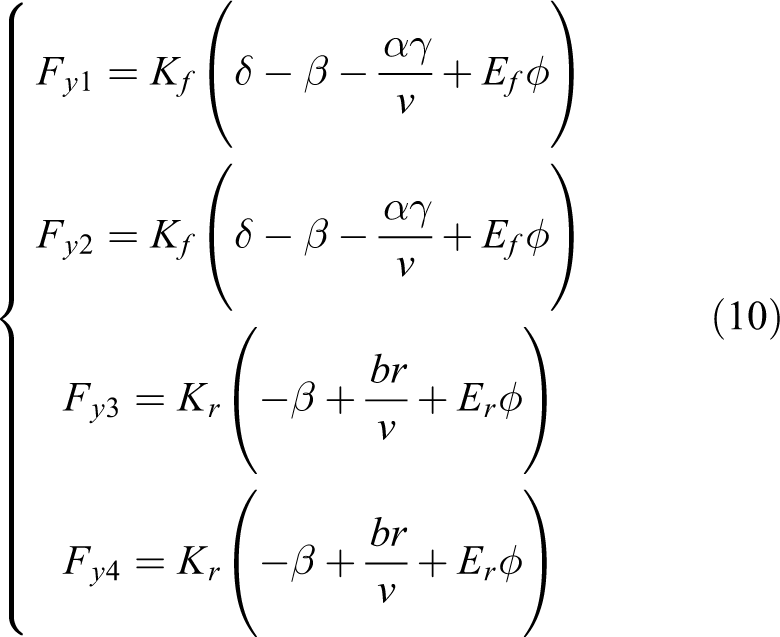
where, Kf
and Kr
respectively denote generalized cornering stiffness of front and rear wheel.
Road excitation model
The external road excitation signals acting on four wheels are generally random signals. Basically, the statistical property of road profile appears to be a homogeneous and ergodic Gaussian random process, being mostly defined by standard of ISO in spatial frequency domain.
The power spectral density (PSD) of road roughness can be defined as follows 21

where n is spatial frequency in
The road profile model in time domain may be expressed in general form of integrated Gaussian white noise, it follows that

where
Note that, the time delay between front and rear wheels, together with the coherence between left and right tracks should be taken into consideration in typical four-wheel road model. Suppose time delay is

Time history of four-wheel disturbance input.
Navigation sensor fault model
From the point of view in vehicle chassis dynamics, typical navigation sensors (like accelerators, gyros) are mainly used to fulfill the measurements of accelerations of sprung mass/unsprung mass or angular rate of pitch/roll. Mathematically, the undesirable sensor faults can be divided into three typical categories: ① deadlocking, ② gain scheduling, and ③ constant deflection. The sensor faults can be modeled as 23

where yi
denotes ideal output of ith sensor (indicating no fault), if if if
H-infinity adaptive observer design for navigation sensor fault reconstruction
Vehicle model with sensor faults
Consider a class of vehicle models with state variables defined by

where
Taking the road excitations and steering input of front wheels as the external disturbances, we define an external disturbance vector, viz

Electronic stability control (ESC) system generates additional yaw torque through controlling the braking or driving force, and these forces are expected to change the tyre longitudinal force on basis of the deviation between the actual vehicle trajectory and the driver’s desired driving trajectory, so that it improves the stability of the vehicle. Analogously, ASS generates active force through the hydraulic actuator to suppress the sprung mass vibration and adjust the tyre deflection, improving vehicle riding comfort and handling stability.
Now we can give the definition of control vector, shown as follows

Considering the riding comfort and handling stability enhanced by the fused vertical and lateral dynamics, the output vector therefore can be designated as

Combining (14)–(17), we primarily construct the system state-space model
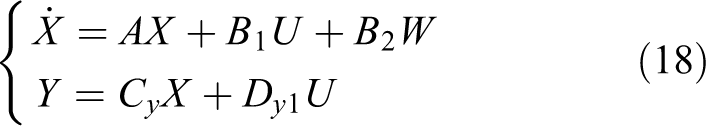
where
The performances of systems largely depend on the information derived from sensors and the control strategies of controllers. In cases where some sensor fails (if controller design remains unchanged), the system performances will deteriorate accordingly, so that the stabilities of system get damaged. For the system represented in (18), we extend its model by introducing an additional term

where
H-infinity adaptive observer with convex optimization strategy
Robust control theory is more general in that it applies to analysis and design of uncertain systems, which deals with two major problems: robustness analysis and robust controller design. As one main thread of robust control theory, H-infinity control attempts to obtain an optimized control strategy by means of infinite norm optimization of some performance indices. In this work, the introduction of H-infinity tracking performance index provides solutions to both observer design and stability condition. Due to the fact that the estimated sensor fault has no relation with fault magnitude, which is changeable only with respect to the variation of fault change rate and given H-infinity tracking performance index, so that, we say, the estimated sensor fault can approximate the real fault with the rule of given H-infinity tracking performance index.
Consider an observer with the following model 24,25

where
The estimation law for this nonlinear adaptive observer is designed by the following general formulation

where
Let state error

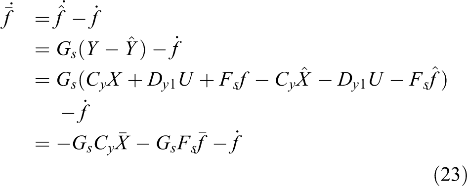
Combing (22) and (23), we define an error matrix in general augmented matrix form
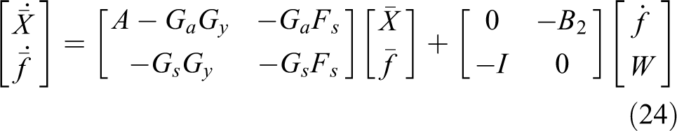
Simplifying (24), we have

with

We further define a positive definite symmetric matrix
Since the augmented error matrix

Formula (27) may imply that w is a disturbance input. Now, we can introduce a H-infinity performance index

By substitution of

The objective of H-infinity control would be to satisfy

Given the above,

Now, we further define two positive symmetric matrixes P and S, and let

Substituting (32) into (30), we obtain (33), where, symbol * represent ‘the symmetric transposition terms of’. Clearly, the derived LMI (33) has product terms with respect to Ga
and Gs
, whose characteristics are non-convex. To solve (33), let


with


Since the feasible solutions


Numerical simulations
To illustrate the effectiveness of the proposed H-infinity adaptive observer for sensor fault estimation, we consider the following faulty vehicle, whose suspension parameters are listed in Table 1.
Vehicle suspension parameters.a

a
Sensor fault settings and descriptions
The simulated step input faults of front wheels are structured in Matlab/Simulink platform. The road profile is assumed to be of B class. Moreover, we are merely concerned with single sensor fault circumstances.
The simulated sensor fault descriptions are listed in Table 2.
Sensor fault location and description.

Simulation results and analyses
The corresponding sensor outputs with/without faults and sensor fault reconstruction results are given in Figures 4 to 9.

Gain scheduling fault-case 1. (a) Sprung mass vertical acceleration output with/without faults. (b) Sprung mass vertical acceleration reconstruction results.

Gain scheduling fault-case 2. (a) Front left suspension dynamic displacement output with/without faults. (b) Front left suspension dynamic displacement reconstruction results.
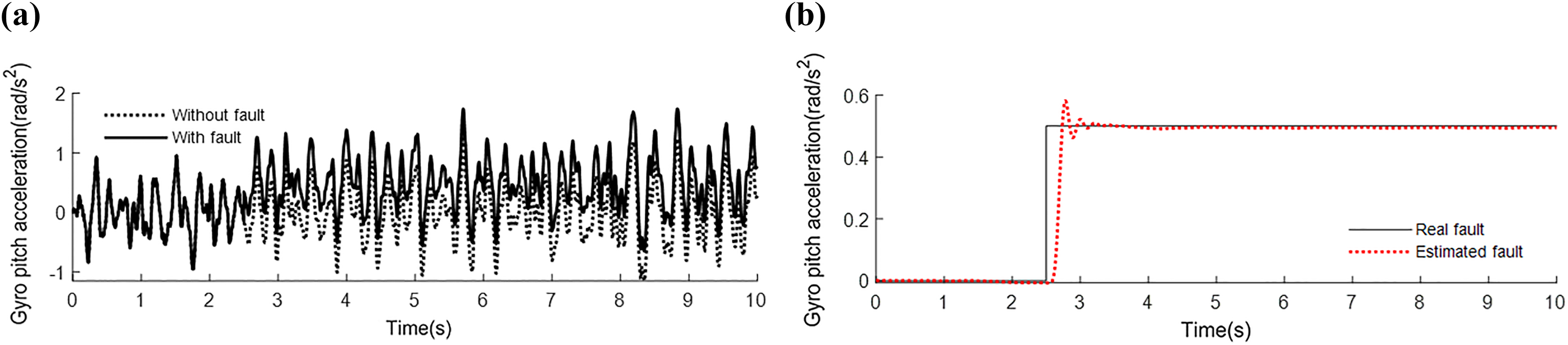
Constant deflection fault-case 1. (a) Gyro pitch acceleration output with/without faults. (b) Gyro pitch acceleration reconstruction results.

Constant deflection fault-case 2. (a) Front right suspension dynamic displacement output with/without faults. (b) Front right suspension dynamic displacement reconstruction results.

Deadlocking fault-case 1. (a) Gyro roll acceleration output with/without faults. (b) Gyro roll acceleration reconstruction results.

Deadlocking fault-case 2. (a) Gyro yaw rate output with/without faults. (b) Gyro yaw rate reconstruction results.
As described in Table 1, gain scheduling faults are set to be hidden on vertical accelerometer and gyros of sprung mass. As in Figure 4, when fault occurs (
Quite similar, before fault occurs, the front left suspension dynamic displacement output appears consistent with no fault output, the observer in operation now can precisely recover the actual sensor output and the estimated fault approximately approaches to 0. When fault occurs (
The simulation results of constant deflection faults (respectively hidden on gyro pitch accelerator channel and right front suspension dynamic displacement channel) are diagrammatically represented in Figures 6 and 7. Operations in the system are made to take place at times when faults occur, as indicated, the estimated fault is making a transition from 0 to 0.5 (see Figure 6(b)) or from 0 to
The simulation results of deadlocking faults (respectively hidden on gyro roll accelerator channel and gyro yaw rate channel) are illustrated in Figures 8 and 9. Quite similar to the constant deflection fault circumstances, even though gyros get stuck, the fault observer can still fast response and track the step input (which is referred to as the most severe operation condition) of real fault, indicating its efficient approximation performances in sensor fault reconstructions.
The application of H-infinity observer-based sensor fault reconstruction in IMUs/GPS
The ideal positioning model of integrated navigation is achieved by combining IMUs with a miniature GPS receiver. It’s worth noting that, the combined IMUs/GPS can be seen as typical inertial navigation system (INS)/GPS integration.
Loosely coupled INS/GPS anatomy
The block diagram of loosely coupled INS/GPS is shown in Figure 10.

Block diagram of loosely coupled INS/GPS.
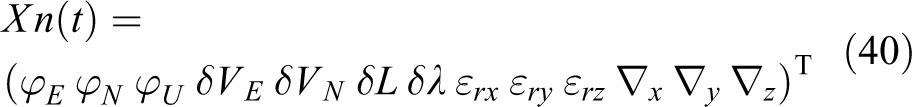
The state equation of INS/GPS is expressed as

where
Denote the navigation coordinate frame by
where
The measurement equation of INS/GPS is expressed as

with


where,
The reconstructed state fused Kalman filter for INS/GPS
Suppose a deadlocking fault took place in GPS north velocity channel. According to the typical discrete Kalman filter model, 27 the block diagram of reconstructed state fused Kalman filter is given in Figure 11.

Block diagram of reconstructed state fused Kalman filter for INS/GPS.
As shown, in cases where deadlocking fault happens, the measurement value of INS/GPS will change accordingly, H-infinity observer designed beforehand, therefore, is expected to reconstruct the priori system state for “State one-step prediction,” which then starts a new Kalman filter process. When the fault is removed, the filtering process goes back to the original pattern, so that the continuity and availability of state estimation tasks are fully ensured. In Figure 11,
Navigation parameter estimation results
The initial navigation condition is designed as follows: The initial roll, pitch and yaw are respectively set to be
Figure 12(a) to (b) and Figure 13(a) to (b) respectively present the latitude and north velocity estimate results during the periods of sensor normally operates and sensor fails. Clearly, when GPS got stuck, the original position and velocity (in geographical coordinate frame) will no longer be accurate. This is illustrated by the divergent curve in Figure 12(b), the increasing difference between the latitude estimate and reference cannot satisfy the reliable navigating and positioning demands of land vehicles.

Latitude estimate result. (a) Latitude estimate during normal operation conditions. (b) Latitude estimate with deadlocking fault in GPS north velocity channel.
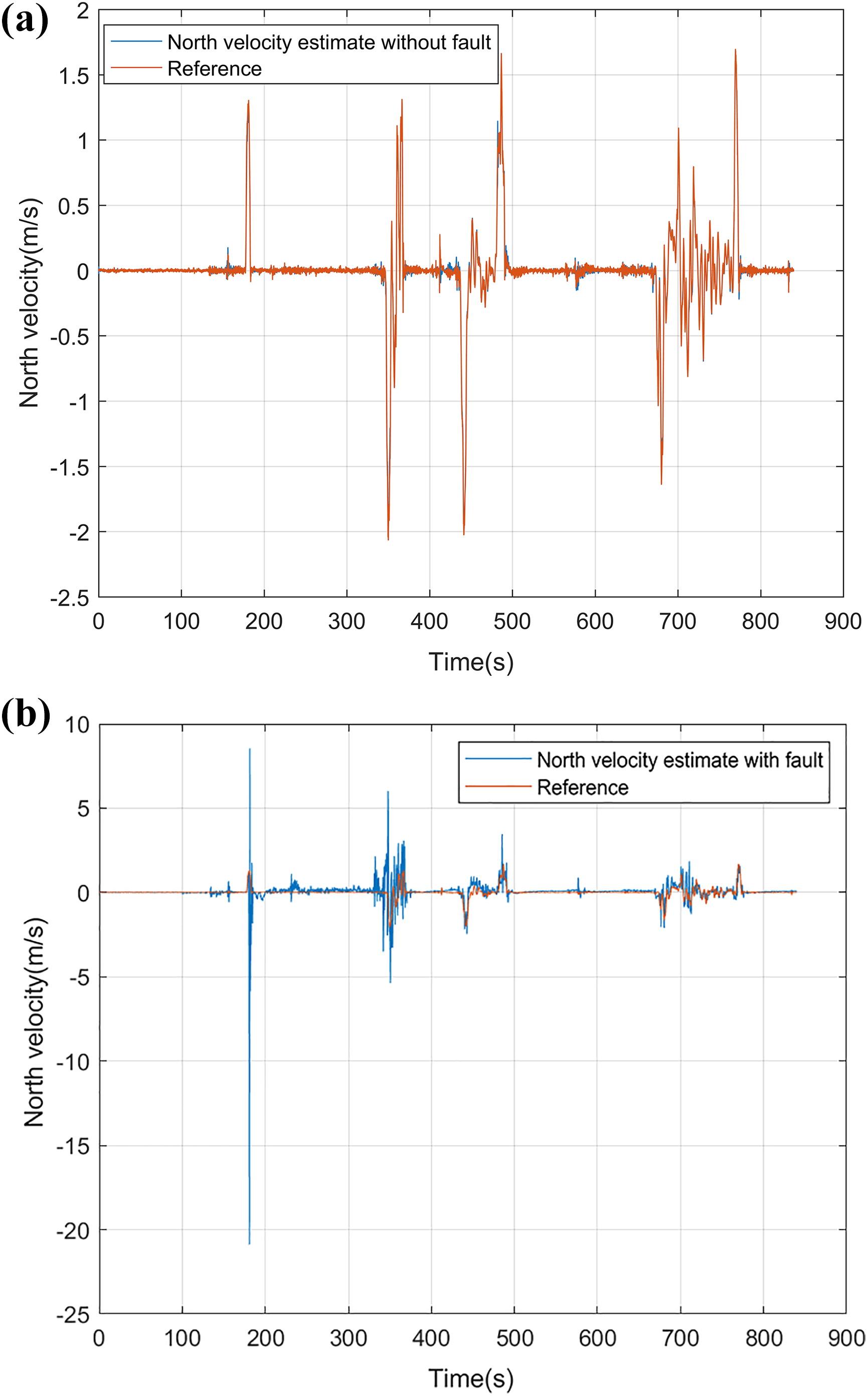
North velocity estimate result. (a) North velocity estimate during normal operation conditions. (b) North velocity estimate with deadlocking fault in GPS north velocity channel.
The compensated latitude and north velocity estimates by means of the proposed sensor fault construction strategy are respectively given in Figures 14 and 15. The results indicate that latitude and velocity estimates stay consistent with their given reference, and the navigation parameters are dependable even though the undesired fault remains unremoved. The vehicle chassis dynamics-based sensor fault construction in terms of H-infinity adaptive observer, therefore, is tested to be valid for practical navigation applications.
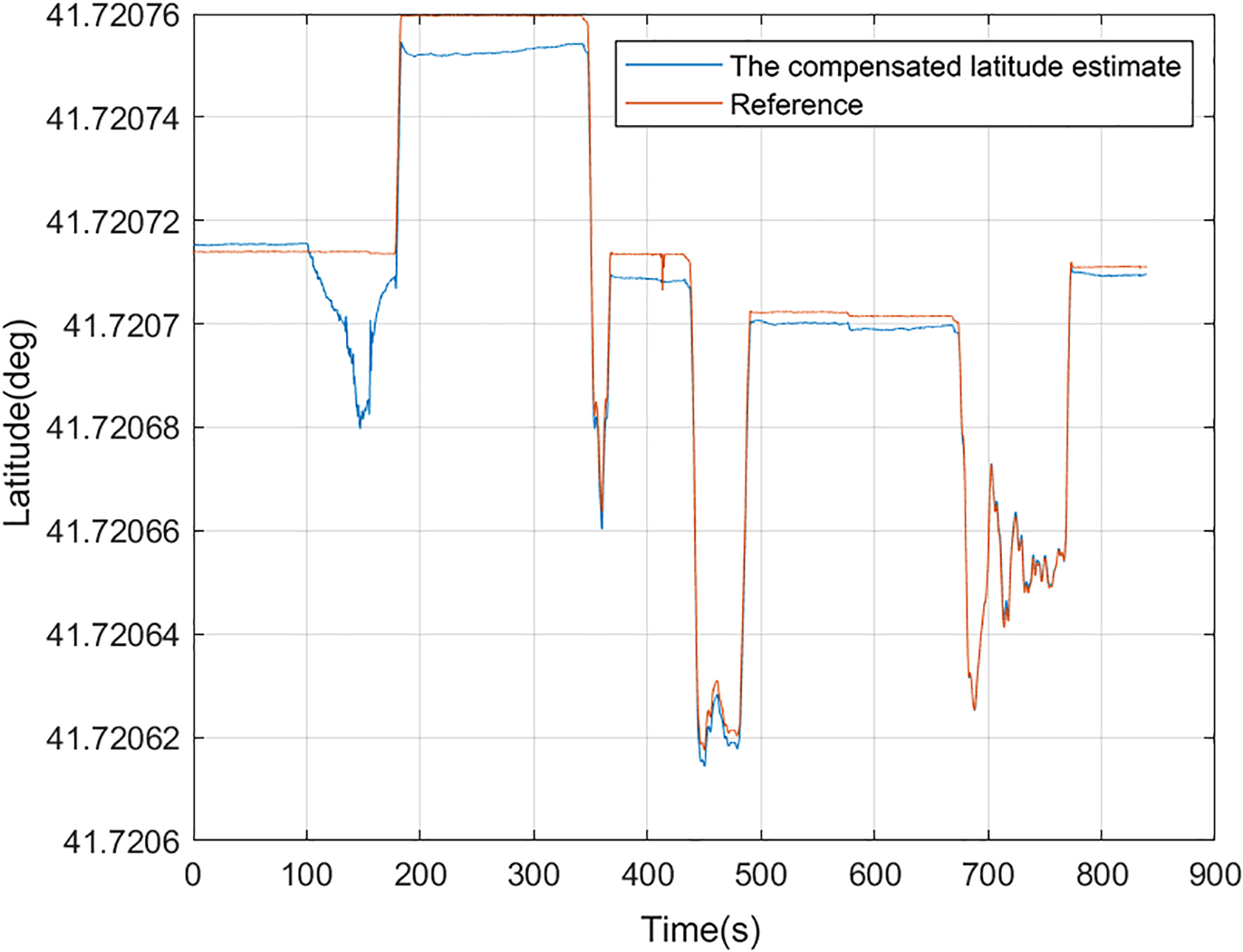
The compensated latitude estimate.

The compensated north velocity estimate.
Conclusion
Due to the undesired faults of navigation sensors, a vehicle chassis dynamics-based H-infinity adaptive observer was employed for sensor fault construction of navigation equipments. With vehicular dynamics, road excitation model and sensor fault model in terms of multiplicative and additive fault fully described, the observer with an augmented descriptor model is theoretically analyzed and constructed, and the gain matrices are consequently evaluated by means of LMI convex optimization. After exhibiting favorable performances of tracking severe step-type inputs when dealing with single-existing sensor fault of deadlocking, gain scheduling and constant deflection, the observer was further assessed by a tightly-coupled IMUs/GPS illustration. It demonstrated that, the compensated navigation parameters (more precisely latitude and north velocity) by state estimator can fairly approach the reference value under GPS north velocity channel denied circumstances. The proposed strategy, therefore, shows its general applicability in navigation sensor fault reconstruction tasks via a class of modern theory-based observer designs and vehicle chassis dynamics-based principles.
Footnotes
Declaration of conflicting interests
The author(s) declared no potential conflicts of interest with respect to the research, authorship, and/or publication of this article.
Funding
The author(s) disclosed receipt of the following financial support for the research, authorship, and/or publication of this article: This research was funded by Natural Research Fund of Science and Technology Department, Jilin Province under Grant 20170101125JC and Research Fund for Distinguished Young Scholars of Jilin City under Grant 20190104128.