
Abstract
Robot-assisted fracture reduction surgery should be highly safe and accurate. It is necessary to accurately determine and control the reduction force of the reduction robot. In this article, a fracture reduction robot is designed with the configuration of the 6-universal-prismatic-universal (6-UPU). The vector method is used to analyze the kinematics of the reduction robot. The Jacobian matrix of the reduction robot and the second-order influence coefficient matrix of the acceleration are obtained. The Lagrangian method is adopted to analyze the dynamic of the reduction robot. The muscle contraction force of the femoral shaft fracture is analyzed based on the Hill model to determine the fracture reduction force. According to changing of the reduction force during the fracture reduction operation, a kind of external force estimation method based on force residual analysis is proposed. When there is no external force sensor at the end of the reduction robot, this method can be used to detect the reduction force in real time. According to the displacement, velocity, and output torque of each branch chain, the reduction force during the reduction operation of the reduction robot can be estimated. A simulation system is conducted and the simulation results show that the fracture reduction force can be estimated and accurately tracked in real time, which is of great significance for the safe operation of the fracture reduction robot.
Keywords
Introduction
The traditional fracture reduction surgery relies mainly on the manual operation of the surgeon to achieve reduction. Since the reduction surgery effect depends on the surgeon experience, the quality of the surgery is unstable and the surgical effect is unsatisfactory. 1 With the development of robotics and image navigation technology, the robot used for fracture reduction surgery has gradually become a hot topic. Compared with series robots, parallel robots have the advantages of high rigidity, high precision, and stable movement, which can be widely used as machine tools, vibration test platforms, precision operations, and medical robots. 2
During the robot-assisted fracture reduction surgery, the robot needs to provide the reduction force in order to balance the muscle force caused by the muscle force. 1 The reduction force needs to be estimated and limited in real time to avoid excessive stretching force to pull the muscle and nerve tissue, which may cause secondary injury to the patient. On the other hand, the collision is likely to occur among the peripheral tissue of distal and proximal of fracture during the reduction process, so the reduction force needs to be detected to avoid serious collisions. If the external force is detected by the force sensors fixed on the robot, they are not only expensive but also easy to be damaged and difficult to be fixed. Meanwhile, there are many noises in the measured information and so on. 3 –5
To overcome the shortcomings above, the external force estimation method with sensorless has attracted widespread attention. At present, many scholars adopt the motor dynamics model to design the disturbance observer to estimate the external force. This method is simple in structure, and the external forces can be estimated by obtaining motor current and motor position information. An additional force sensor needn’t to be installed on the robot system.
6
–9
For the series manipulator, the contact force and contact position can be estimated simultaneously by using the nonlinear optimization method, and the algorithm is experimentally verified in the robot arm.
10
To achieve the direction adjustment at the force action point while obtaining the desired velocity, the residual force method is used to estimate and locate the contact force. A generalized hybrid force/velocity control method is adopted at the contact point.
11
For the shortcomings of easily generating noise using the disturbance observer, a disturbance observer based on Kalman filter is designed to estimate the external force. This method has the advantages of wide bandwidth, no sensor noise, and so on.
12,13
According to the robot dynamics model, the generalized momentum observer method is adopted to estimate the external force. This method can estimate the external force only by measuring the joint displacement and velocity information, and it does not need to calculate the acceleration and inertia matrix.
14
–18
The contact particle filter method is used to detect and locate the external contact of the robot without an external sensor. Even if the external torque measurement is corrupted by noise, it can return a reasonable estimate value.
19
The Kalman filter is adopted to extend the generalized momentum observer, and the contact force and moment at the center point of the end tool are estimated online, which can increase robustness with respect to disturbances such as uncertainty in joint friction.
20
The neural network is trained as robot dynamics with or without external contact by the Levenberg–Marquardt algorithm, and the robot sensor is used to detect the collision quickly and efficiently.
21
The
For robot-assisted fracture reduction surgery, considering the operating environmental conditions, it is difficult to install the force sensor at the end of the reduction robot. In order to detect the force information in real time during reduction surgery operation for improving the force control and the surgery safety, the external force estimation method of the robot-assisted femoral fracture reduction is studied. The kinematics of the reduction robot is analyzed by the vector method, and the Jacobian matrix of the reduction robot and the second-order influence coefficient matrix of the acceleration are obtained. The Lagrangian method is used to analyze the dynamics.
Based on the Hill model, the muscle contraction force during the fracture region is analyzed to determine the fracture reduction force. A force residual observer for the robot-assisted fracture reduction system is constructed to detect the reduction force at the distal end of the fracture during the reduction operation. Simulation experiments are carried out to verify the effectiveness of the proposed method for estimating the fracture reduction force by the force residual observer. Simulation results show that the force residual observer only needs to obtain the displacement, velocity, and output torque of each electric cylinder of the parallel robot, then the fracture reduction force can be estimated and the change of the reduction force can be accurately tracked.
Reduction robot
The robot-assisted fracture reduction surgery system with 6-UPU configuration is shown in Figure 1. It consists of a distal gripper, a proximal gripper, a reduction robot, a lifting platform, a movable base, and an optical surgical navigation system. The proximal gripper is mounted on the operating bed, and the proximal end of the femur is fixed by the bone needle. The distal gripper is mainly used to fix the distal end of the femur. The distal gripper is mounted on the reduction robot and connects the distal end of the femur to the reduction robot by the bone needle. The reduction robot can translate and rotate along the x, y, and z axes, with six degrees of freedom to meet the motion requirements of fracture reduction. The movable base is mainly used to install the lifting platform and the robot controller, and the reduction robot is mounted on the lifting platform. The height of the robot can be adjusted manually by the lifting platform to meet the needs of robotic surgical operations. The optical surgical navigation system is mainly used for the positioning of the proximal and distal ends of the fracture during the fracture reduction.

Fracture reduction robot system.
The structural characteristics of the reduction robot with six-degree-of-freedom parallel robot are shown in Figure 2(a). It is mainly composed of six electric cylinders, an upper platform, and a lower platform. The upper platform is connected to the lower platform by the electric cylinders. The end of each electric cylinder is equipped with two universal hinges.
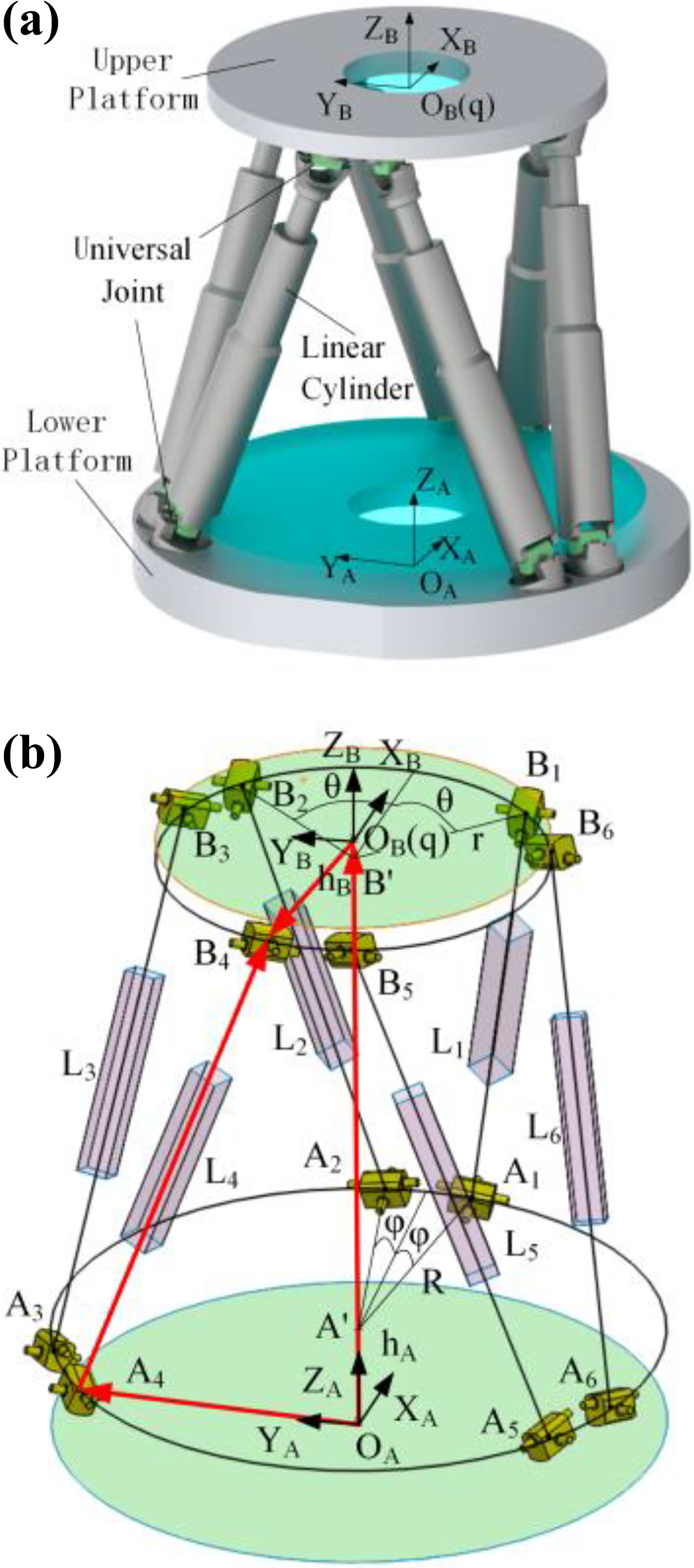
(a) 6-UPU parallel robot. (b) Structure parameters.
The structure parameters of the parallel robot are shown in Figure 2(b). The height of the bottom surface of the lower hinge center is hA
, and the distance from the center plane of the upper hinge to the top of the upper platform is hB
. During the movement of the robot, the center plane of the hinge is unchanged with respect to the position and orientation of the upper platform and the lower platform, respectively, so hA
and hB
are constant. Therefore, the bottom center plane of the lower hinge and the bottom surface of the lower platform can be converted by hA
, and the center plane of the upper hinge and the top surface of the upper platform are converted by hB
.
Using the method of homogeneous coordinate transformation, setting the position coordinate of the origin of the coordinate system of the upper platform{

where
In the space coordinate system, the coordinates of any point on the moving coordinate system {

Kinematic analysis
The generalized velocity of the moving platform of the parallel robot is expressed as
The angular velocity

The forward speed of the parallel robot is

where
The expression of the positive acceleration solution of the parallel robot is 24

where
Dynamic analysis
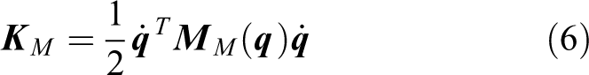
The Lagrangian method is used to analyze the dynamics of the reduction robot. The reduction robot is divided into two subsystems: the moving platform and the six electric cylinders. The kinetic energy and potential energy of two subsystems are analyzed, respectively. The Lagrangian formulation of the robot can be established. Finally, the partial derivative of the Lagrangian formulation is derived, and the dynamic equation of the robot can be obtained. 25,26
The kinetic energy of the moving platform in the generalized coordinate space is

where mM is the mass of the moving platform; and Ix , Iy , and Iz are the moment of inertia of the moving platform about the x, y, and z axes, respectively.
The parameters of the electric cylinder are shown in Figure 3. m
1 and m
2 are the mass of the cylinder and the piston, respectively.

Electric cylinder structure diagram.
The kinetic energy of a single electric cylinder is

where
The kinetic energy of six electric cylinders is

where
Therefore, equation (9) can be expressed as

Then, the inertia matrix of the electric cylinder can be obtained as follows

In the operating space, the Lagrangian dynamic equation can be expressed as

where
The Coriolis force/central force coefficient matrix

Where
The Coriolis force/central force coefficient matrix CM of the moving platform is calculated according to equation (13) and is expressed as follows

where the parameters are detailed in the literature. 26
As the rotating angle of the piston with respect to the cylinder is relatively small, then the Coriolis force/centripetal force of the piston is very small. It is usually not considered,
The gravity of the moving platform is:

The gravity of the electric cylinder is

where
The three-dimensional (3-D) model of the fracture reduction robot is established in SolidWorks 2018 software. The related parameters of the model are measured in the software, as shown in Table 1.
Dynamics parameters of 6-UPU robot.

Generally, it is difficult to obtain the parameters of the moving platform. The displacement and velocity of the electric cylinder can be easily obtained from the encoder. The driving force can be obtained from the force sensing of the electric cylinder. The robot dynamics is expressed in the joint space as follows

where


Analysis on fracture reduction force
As there are tensor fascia lata and semitendinosus and semimembranosus in the fracture area, these muscles are still in a continuous state after fracture. The force generated by the muscle stretching is the reduction force, which is the most important load during the fracture reduction and has a great influence on the accuracy and effect of the reduction.
28
Compared with other complex muscle force models, the Hill model is a phenomenon model, which is more reasonable for evaluating of overall muscle force.
29
AV Hill proposed a skeletal muscle three-element model to describe muscle force and assumed that the muscle force

Hill skeletal muscle force model.
The mathematical expression of the Hill model is

where
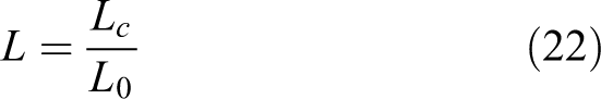
where L 0 is the optimal muscle fiber length. Lc is the muscle fiber length after stretching.
Before the femoral fracture is restored, the relaxation agent is injected into the fracture area in order to prevent the nerve impulses being transmitted to the muscles. At this time, the muscles have only passive stretching force. 31 The expression of muscle force during reduction is

where
The fracture reduction robot is shown in Figure 5. The acting position and direction of the reduction force is shown, which is expressed as

Reduction force action diagram.
As the reduction force is the largest along the direction of the femoral shaft axis, so the reduction force can be simplified as
The maximum reduction force of the femoral shaft fracture is 396 N. Setting the feather angle between muscle fibers and tendons, α(t) is 0. 28 The optimal muscle fiber length L 0 is 90 mm. 29 Combined with the path planning of this subject, the maximum displacement along the x-axis during the reduction process is 25.94 mm, and the maximum length of muscle fibers after muscle stretching is 115.94 mm.
The reduction force of the robot changing with the x-axis distance can be calculated by equation (23), as shown in Figure 6. The reduction force gradually increases with the increase of the x-axis displacement. When the x-axis displacement is 25.94 mm, the reduction force reaches maximum value of 396 N.

The relationship between axial reduction force and muscle stretch length.
External force estimation
The external force estimation based on the force residual is widely used in the series robot, which can realize the external force estimation and collision detection during the movement of the manipulator. 14,32,33 At present, for the fracture reduction robot, a force sensor is generally fixed at the end of the reduction robot to obtain the reduction force during the fracture reduction. 34,35 Due to the particularity of the fracture reduction surgical environment, installing a force sensor will limit the clamping of the distal segment of the broken bone. Therefore, the external force estimation method based on force residual is proposed for the fracture reduction robot, especially for the robot with the parallel configuration. The proposed method can effectively avoid the installation of sensors at the end of the parallel robot.
When the reduction robot collides with the environment during the fracture reduction, the generalized momentum of the robot is generally changed greatly. 36,37 The force residual method based on the generalized momentum is proposed in this article. The fracture reduction force is estimated in real time by detecting the displacement, velocity, and output torque of the electric cylinder during the robot reduction operation. The acceleration of the electric cylinder need not to be detected. The force residual observer is equivalent to using a virtual force sensor between the surgical robot and the fraction region.
Considering the reduction force, the dynamics equation is modified as

where
The reduction force

where
Defining the generalized momentum of the reduction robot is as

Doing the partial deviation of equation (26)

Therefore,

From equations (24), (27), and (28), the following equation can be obtained

Since equation (29) shows that
The force residual observer is defined based on the momentum deviation to estimate the external force value, and the force residual signal
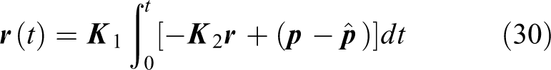
where

When only the equation above is used as the observer, a large delay and oscillation are generally generated. 33 So constructing an adjustment function is as follows

Taking fc as the feedforward adjustment of equation (31), the effective residual observer is

where
The structure diagram of the force residual observer is designed, as shown in Figure 7.

Force residual observer block diagram.
Find the second-order partial derivative for equation (33) and bring the result into equation (29)

For ith electric cylinder component of the parallel robot, the Laplace transform is performed on equation (34), and the transfer function of the observer system is

From equation above, it can be seen that the force residual observer is a second-order system, whose output is the force residual observation value

It can be concluded from equation (36) that the reduction robot can estimate the reduction force of the fraction region during the robot reduction operation by using the force residual observation value
Simulation
MATLAB/Simulink 2018b software is adopted to simulate the robot-assisted femoral fracture reduction, and the force residual observer is designed to estimate in real time the reduction force during the robot reduction operation. Simulation system with force residual observer is shown in Figure 8. The desired path of the reduction robot is preoperative planned. Then, the displacement of each electric cylinder is calculated by the kinematics inverse solution based on the desired path. The proportion integration differentiation (PID) controller block controls the displacement of the linear electric cylinder, and the muscular force block is used to add an external reduction force to the marked point

Simulation system with force residual observer.
The reduction path is planned according to the fraction model by the A* algorithm, and the planned reduction path is indicated by “ ” in Figure 9.

Marking point trajectory.
Selecting a feature point on the distal fracture as the marking point
Simulation without reduction force
When the reduction force is not considered, the robot-assisted fracture reduction is simulated. The actual movement trajectory of the marked point  ,” as shown in Figure 9. The error between the planned reduction path and the actual path of the marking point

Motion error of marked point.
When the reduction force is not considered, the robot is only affected by its own inertial force, Coriolis force, and centrifugal force and gravity. Simulation results of the driving force of each cylinder is shown in Figure 11, which is mainly used to balance the robot gravity.

Driving force of each electric cylinder.
As shown in Figure 12, during the robot fracture reduction operating, due to the low speed of the robot, the inertial force, Coriolis force, and centrifugal force of the robot are much smaller than itself gravity and can be ignored.

Driving force of electric cylinder expressed in operating space.
The force residual observer is used to estimate the external force during the robot reduction operating, and the external force obtained includes the gravity and inertial force. In order to detect the external reduction force more clearly, the force residual observer needs to be initialized before the robot reduction. Thus, the reduction force observer output value is approximately 0 N. When no reduction force is applied, the external force value outputted by the force residual observer is approximately 0 N, as shown in Figure 13.
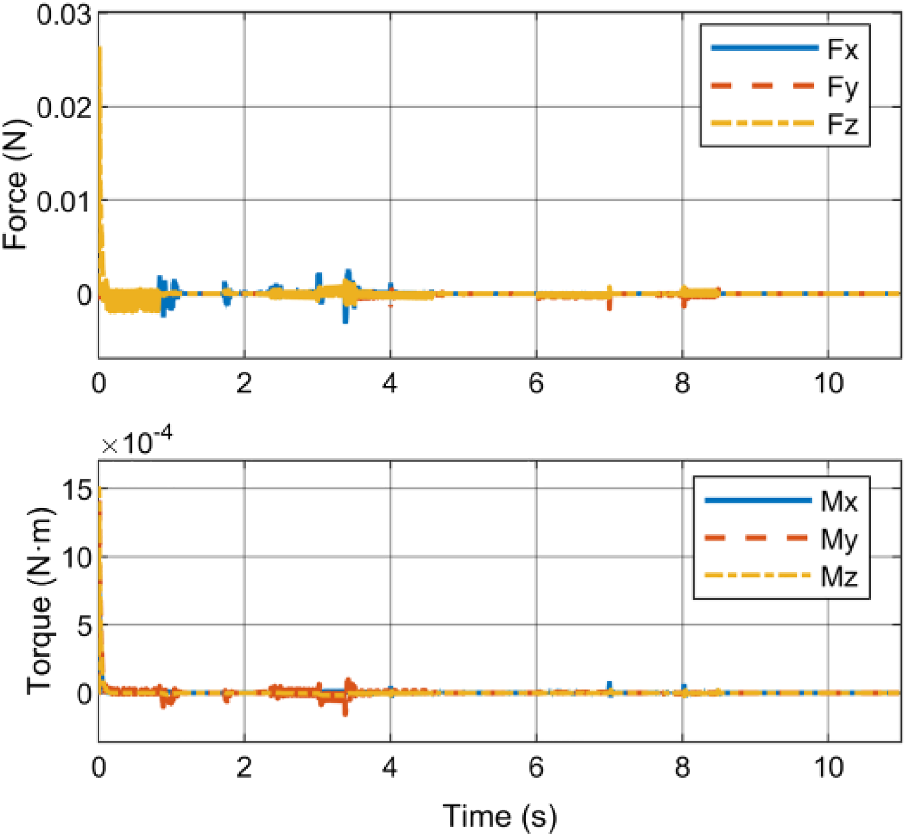
External force value by the force residual observer.
Simulation with reduction force
Applying a reduction force to the fracture reduction robot, the simulation is performed. The position and direction of the reduction force are shown in Figure 5, and the variation is shown in Figure 6. The position and orientation error of the marker point

Motion error of distal segment with acting the reduction force.
According to the simulation results, the driving force of each electric cylinder is shown in Figure 15. The driving force of the electric cylinder gradually increases with increasing the fracture reduction force. At the end of the reduction operation, the maximum driving force of the electric cylinder reaches −411 N, which can be used as a reference for the selection of the electric cylinders.

Driving force of each electric cylinder with acting the reduction force.
The driving force of the electric cylinder is calculated by the Jacobian matrix and expressed in the generalized coordinate space. As shown in Figure 16 at the end point of the fracture reduction, the generalized driving force of the electric cylinder is [−394 N, −5 N, −106 N, −3 N·m, −19 N·m, −11 N·m] T during the reduction process, and the driving force of the robot cylinder is reduction. The robot’s gravity and fracture reduction force are balanced. The torque generated in Figure 16 is due to the fact that the center of gravity of the reduction robot gravity and the direction of the reduction force do not coincide with the direction of the origin of the coordinate of the reduction robot.

Driving force of electric cylinder in operating space with acting the reduction force.
The fracture reduction force estimated by the force residual method for robot-assisted fracture reduction system is shown in Figure 17(a) and (b). At the reduction end point, the force-reduction observer estimates the restoring force to be [392 N, 0, 0, 0, 13 N·m, 5 N·m] T . The force residual observer along the x-axis direction measured as 392 N.

(a) External force by force residual observer. (b) Torque by the force residual observer.
From Figure 6, the maximum of the reduction force of the femur is 396 N, and the error is about 4 N (1.01%). Comparing Figures 6 and 17, the trend of reduction force is consistent. The force residual method can effectively estimate the reduction force. As shown in Figure 17(b), there is external moment of the simulation results. This is because the direction of the reduction force does not pass the coordinate origin of the robot.
Conclusion
In order to improve the safety of robot-assisted fracture reduction operation, a kind of external force estimation method based on the force residual analysis is proposed. By this method, the reduction robot can detect the external force in real time without installing an external sensor. The external force estimation only needs to measure the displacement and velocity information of the robotic cylinder to detect the reduction force at the distal end of the fracture without detecting and calculating the acceleration. In order to verify the validity and correctness of the external force estimation method, the simulation of the robot-assisted fracture reduction system is conducted in the MATLAB/Simulink software. The external force estimation can detect the reduction force in real time and accurately track its changing during the reduction operating. At the end of the reduction operation, the error of the external force estimate value is 4 N. The proposed method has certain universality, which can be applied to estimate the external force not only the femoral fracture reduction but also the various fracture reduction, such as pelvis and tibia.
In future, the force/position hybrid control algorithm of the reduction robot will be studied based on the fracture reduction force detected in real time by the force residual analysis, which will improve the safety of the robot-assisted fracture reduction.
Footnotes
Declaration of conflicting interests
The author(s) declared no potential conflicts of interest with respect to the research, authorship, and/or publication of this article.
Funding
The author(s) disclosed receipt of the following financial support for the research, authorship, and/or publication of this article: This work was supported by National Key R&D Program of China (grant no 2017YFB1304202) and the National Natural Science Foundation of China (grant no. 51775323, no.51375289).