
Abstract
In this article, we present a novel high-performance millirobot (
Introduction
Small robots, typically categorized as milli-, micro- or nanorobots, 1 –3 have applications in a variety of areas. Some applications include use in surveillance, 4 –6 wilderness search and rescue, 7 –11 urban search and rescue, 12 –14 medicine, 15,16 micro-assembly 17 and wireless sensor networks. 18,19 In the work of Kashino et al., 7,8 a millirobot was used to perform wilderness search and rescue experiments in a scaled-down lab environment. Fearing 12 suggested to use millirobots to locate survivors in a collapsed building by spreading through narrow and complex passages. Yim et al. 16 proposed a wireless biopsy method wherein a soft capsule (pill) robot equipped with a camera and wireless communication module is actuated inside the human body. In the work of Vartholomeos et al., 17 high-precision motion of a millirobot demonstrated the potential to use them for micro-assembly tasks. Other designs of note include self-folding origami robots, 20 bio-inspired legged robots 21,22 and units that can pull objects heavier than their own body weight. 23
Millirobots have also been used as research tools in testing swarm algorithms that aim to have a group of decentralized, self-organizing agents exhibiting collective behavior. 24 Such small, cost-effective robots have allowed scientists to study both autonomous and supervised swarm tasks in confined workspaces with hardware experimentations. 25,26
In the above context, our focus has been on the design of a novel high-performance millirobot,
Furthermore, herein, we also present a new method for swarm-topology estimation that utilizes the capabilities of mROBerTO to estimate the overall topology of the swarm. The method is novel in that it uniquely fuses incomplete data, collected in a distributed manner, using a centralized algorithm. It should be noted that, while the method was designed with mROBerTO in mind, it is a generalized technique. Namely, any swarm, comprising robots capable of collecting location estimates of neighbouring robots, could utilize the proposed method.
Millirobot designs
Millirobot designs for swarm applications reported in the literature include GRITSBot, 30 TinyTeRP, 31,32 Wanda, 33 AMiR, 34,35 Jasmine 36 and Alice II. 37 Alice II, for example, incorporates watch motors for locomotion, can be equipped with a linear camera and supports radio communication. However, it is limited in processing power and cannot detect proximity or bearing information of its neighbours. Jasmine is equipped with micro direct current (DC) motors and utilizes six infrared (IR) emitter/receiver pairs for all-around sensing and communication coverage. TinyTeRP uses geared motors and has an all-terrain add-on. GRITSBot achieves locomotion with micro stepper motors, comprises three stacked layers, each with varying sensors, and has all-direction IR sensing coverage. AMiR allows for modularity, where one such application is the incorporation of microphones for detecting neighbours. However, as does TinyTeRP, it has limited processors, and thus, local processing of received signals and local communications are not implemented.
Other millirobots include the Kilobot 38 and the Colias. 39 Kilobot uses a single IR LED for communication with its neighbours and achieves motion using two coin-shaped vibration motors. Colias is a 40 × 40 mm2 robot that can move up to a speed of 350 mm/s.
Larger swarm robots (>75 × 75 mm2 footprint) have also been reported on, such as the E-Puck, 40 the SwarmBot 41 and the R-One. 42,43 These have a wide range of sensory capabilities, high-performance processors and relatively long battery lives.
Only a few millirobots, such as the E-Puck and the Kilobot, are commercially available. 44,45 Furthermore, due to their small sizes, the above-mentioned units have been be limited in their communication, locomotion and sensing capabilities. 46 Locomotion selection and design have proved to be, particularly, challenging since conventional technologies do not scale well downward and are often limited in terms of power output. This has made it difficult for researchers to test complex swarm algorithms via currently available physical millirobots, including unknown environment exploration, 26,47,48 target searching 49,50 and HSI. 46,51
Herein, thus, our goal is to present a novel millirobot with a combination of high-performance processing, sensing, communication and locomotion features developed to overcome some of the design limitations of earlier small millirobots. These advanced features are achieved while keeping the unit size comparable to the smallest existing millirobots. The proposed design has a novel sensing module for localizing neighbouring robots without requiring their relocation or the use of anchors.
Swarm-localization and topology estimation
Typical swarm behaviours, such as distributed sensing for obstacle avoidance, and area coverage, have been achieved using classical physics-based techniques, where only neighbouring robots interact. 46,52 Furthermore, the algorithms developed have been evaluated in controlled environments with simple problem instances (e.g. minimal obstacles with few robots). 53 More complex behaviours, such as swarm-formation management, require robots to have greater knowledge regarding the overall global state of the swarm including the positions of all the robots (e.g. tasks that feature irregular swarm formations and task allocations in dynamic environments). 50,54 Such position knowledge is also essential in HSI scenarios, where the human supervisor needs knowledge regarding the state of the swarm to guide it towards completing tasks such as foraging, searching for and localizing a radiation source, and search and rescue missions. 26,46,49,51,55,56
Estimating the locations of swarm members, for purposes such as those discussed above, is termed swarm localization and is, typically, an online process. 26 Online localization can be carried out either using an external infrastructure 57,58 or on-board sensors, 59 –71 where the latter is more robust as it eliminates reliance on structures or entities outside of the swarm. Range-based methods of localization using on-board sensors, which require the robots in the swarm to directly measure their relative proximity and bearing with respect to other neighbouring robots, are common. 59 However, such algorithms require either for the robots to be in motion (i.e. relocated) 60 –64 or at least one robot to act as an anchor with known global coordinates. 65 –71 Furthermore, there have been only a few studies showing the implementation of localization algorithms via physical robots and, even when they are, experiments have been restricted to two or three robots at most. 63,64
Information acquired through localization can be used to address the topology estimation problem, where the objective is to recover the ‘shape’ of the swarm. Previous research, primarily, considered the calculation of a set of statistical parameters to define the topology of the swarm. 72,73 In the work of Lantao et al., 72 for example, estimates of the longest network distance between any two robots, in any direction, as well as the average distance between robots are used for this purpose. Similarly, Freeman et al. 73 describe an algorithm for estimating summary statistics, such as the swarm’s inertial moments, that describe the shape of the swarm. However, research on the direct use of robot relative positions to estimate a swarm’s topology has not been so far reported in the literature.
In this article, thus, we present a novel global swarm-topology estimation method that calculates the detailed swarm topology via the relative positions of all robots with respect to each other. It uniquely utilizes incomplete data sets of relative robot positions and bearings to estimate the overall topology of the swarm that can be used for HSI experiments. It comprises a unique combination of distributed and centralized computing to reap the benefits of both. The algorithm is a generalized technique. It can be utilized by any swarm with robots capable of obtaining location estimates of neighbouring robots (as can mROBerTO).
Problem statement
As outlined above, millirobots often have limited sensing and communication capabilities and are difficult to build due to their small size. These factors complicate their use for swarm-behaviour studies, especially, in the case of HSI experiments. The first problem addressed in this article, therefore, is one of designing a high-performance millirobot for HSI that is of similar size to the smallest existing millirobots. Additionally, the millirobot should be easy to build and maintain despite its small size.
In terms of capabilities, a swarm robot for HSI requires reliable locomotion, advanced processing and sensing capabilities and long-range (wireless) communication ability. Namely, a swarm robot needs to efficiently and effectively communicate with and sense other robots in its vicinity. It could benefit from modularity to allow for future improvements.
As also above-mentioned, an essential part of HSI is swarm-topology estimation. In remote HSI, the human supervisor interacting with the swarm will, typically, not be able to observe the swarm directly. Instead, the supervisor must rely on information gathered from the robots to estimate the state of the swarm. One key swarm-state variable that is often important to the supervisor is swarm topology (i.e. where the robots are relative to one another). It is, therefore, necessary to present an accompanying swarm-topology estimation algorithm when advocating a robot design for HSI studies. To this end, given our proposed robot’s capabilities, the second problem addressed in this article is swarm-topology estimation.
In the swarm-topology estimation problem addressed herein, the only sensors available to observe the swarm must be on-board the robots themselves. Data acquired are, therefore, limited in scope to what the robots can sense and collect. Since swarm robots interact locally, each robot would only be able to acquire information regarding other robots in its vicinity. The objective of swarm-topology estimation is to effectively fuse incomplete data sets acquired by the robots in order to provide the supervisor with an estimate of the complete swarm topology.
Overview of University of Toronto milli-robot design
A new ground swarm robot was designed and built at the University of Toronto – mROBerTO. 27 –29 The design is novel in that it has a simple modular architecture, utilizes a high-power processor with integrated wireless communication and has a sensing module capable of localizing neighbouring robots in a decentralized manner without the need for robots to relocate or use anchors. It is the first millirobot to be designed with remote HSI studies in mind, incorporating both wireless and local communication into its base design.
As noted above, the 16 × 16 × 32 mm3

mROBerTO’s exploded-assembly (front and back views). mROBerTO:
Each of the above-mentioned modules, as well as their integration, is described in detail in the work of Kim et al.
27,28
and Drisdelle et al.
29
– as such, they are omitted herein. The specific description of the swarm-sensing module below, thus, is only due to its immediate relevance to the swarm-topology estimation algorithm proposed in this article. A video describing
The swarm-sensing module
The swarm-sensing module of mROBerTO enables swarm-behaviour monitoring and formation control. Namely, it was designed for localized communication and localization. This module has six IR detectors and four emitters at the edges of the module, allowing for all-direction coverage, as shown in Figure 2.

Swarm-sensing module with six IR detectors on top and four emitters on the bottom.
IR was selected for its usability in concurrent localization and communication. Six detectors were used to make full use of the analogue-to-digital converters available and maximize the angular resolution of measurements. Four emitters were used, as this was enough for all-around coverage. This module also houses a secondary microcontroller, an ATmega328, which is tasked with the processing of the received IR signals. The processing tasks include signal modulation and demodulation as well as signal interpretation to acquire proximity and bearing information.
An mROBerTO can acquire proximity and bearing information from other robots while remaining static (i.e. they do not need to relocate). In contrast, other millirobots of similar size, such as Alice II, 37 Jasmine 36 and TinyTeRP, 31 can only obtain proximity and bearing information by requiring their neighbours to move for triangulation. 60 –63,65
Swarm-topology estimation
In HSI scenarios, a human supervisor can provide assistance either through direct commands or guidance to individual robots or to the swarm. 51,55 A key swarm-state that must be, thus, real-time observable to the supervisor is the swarm’s topology. For example, in both swarm-formation management and location-dependent task allocation in large swarms, knowing the swarm’s topology is essential for effective decision-making.
Typically, a swarm would operate in a remote location away from the human supervisor, who would have no way of directly observing the swarm, for example, via overhead sensors. Thus, herein, we present a new global swarm-topology estimation method that only utilizes information collected from the swarm robots and transmitted to a central computer. The algorithm is novel in that it only utilizes partial location data sets obtained from individual robots and fuses them to estimate the full swarm topology. Furthermore, the algorithm does not require prior knowledge of the global position of any of the swarm members or surrounding environment features.
The proposed swarm-topology estimation method consists of two phases: (I) distributed relative localization, through data acquisition from the swarm robots, and (II) swarm-topology estimation, via a central computer (see Figure 3).

A two-phased global swarm-topology estimation method.
The first phase is carried out using the on-board processing and sensing capabilities of mROBerTOs, where each robot determines the relative locations of its respective neighbouring robots that it can detect. The second phase begins after the centralized host PC receives the relative location data sets from the swarm robots. However, in large swarms, computational scalability may become a concern if the topology estimation process depends entirely on a centralized computer. Thus, scalability is addressed herein through a divide-and-conquer approach that increases computational efficiency via grouping and stitching. 75
One can note that the proposed algorithm is centralized in that all collected data is fused at a central computer to obtain an optimal swarm-topology estimate. The distributed portion of the method, on the other hand, is in data collection and initial interpretation, which is performed individually by each robot. Furthermore, all information is acquired from individual robots, and the central system cannot externally observe the swarm (i.e. there are no overhead sensors monitoring the environment in which the swarm is operating).
Phase I: Distributed relative localization
Relative (distributed) localization by an mROBerTO is carried out by measuring the proximities and bearings of nearby robots via its swarm-sensing module. The inclusion of the ATmega328P microcontroller within the swarm-sensing module provides mROBerTO with the unique feature of dedicated processing for localization. This allows it to acquire both proximity and bearing information without adding to the computational load of the main processing unit.
Determining the proximity and bearing to neighbouring robots begins when the IR emitters on mROBerTOs send out modulated signals through PWM. The signals are encoded with the robots’ unique IDs such that receiving robots can differentiate between signals received from different robots. The signals received by IR receivers are passed on to the ATmega328P microcontroller and demodulated to identify the respective robots emitting the signals. Once the IR signals are demodulated, the raw IR amplitudes for each nearby robot are normalized and summed

where ai is the normalized and summed IR amplitude value for the ith robot, IR ik is the IR amplitude reading value for the ith robot and the kth IR detector, and IRmaxik is the maximum IR amplitude value recorded during offline calibration. ai values are converted into proximity measurements according to a conversion function obtained during offline calibration.
Each mROBerTO determines the bearing of a nearby robot using the normalized IR amplitudes from each IR detector as the six wide-viewing angle (120°) IR detectors are configured for an all-around coverage. The normalized IR amplitudes from these six IR detectors are weighted to determine at which angle the signal was the strongest and estimate the bearing towards the neighbouring robot 74
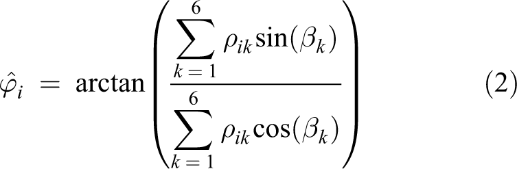
where βk
is the angle between the robot’s heading and the kth sensor, and

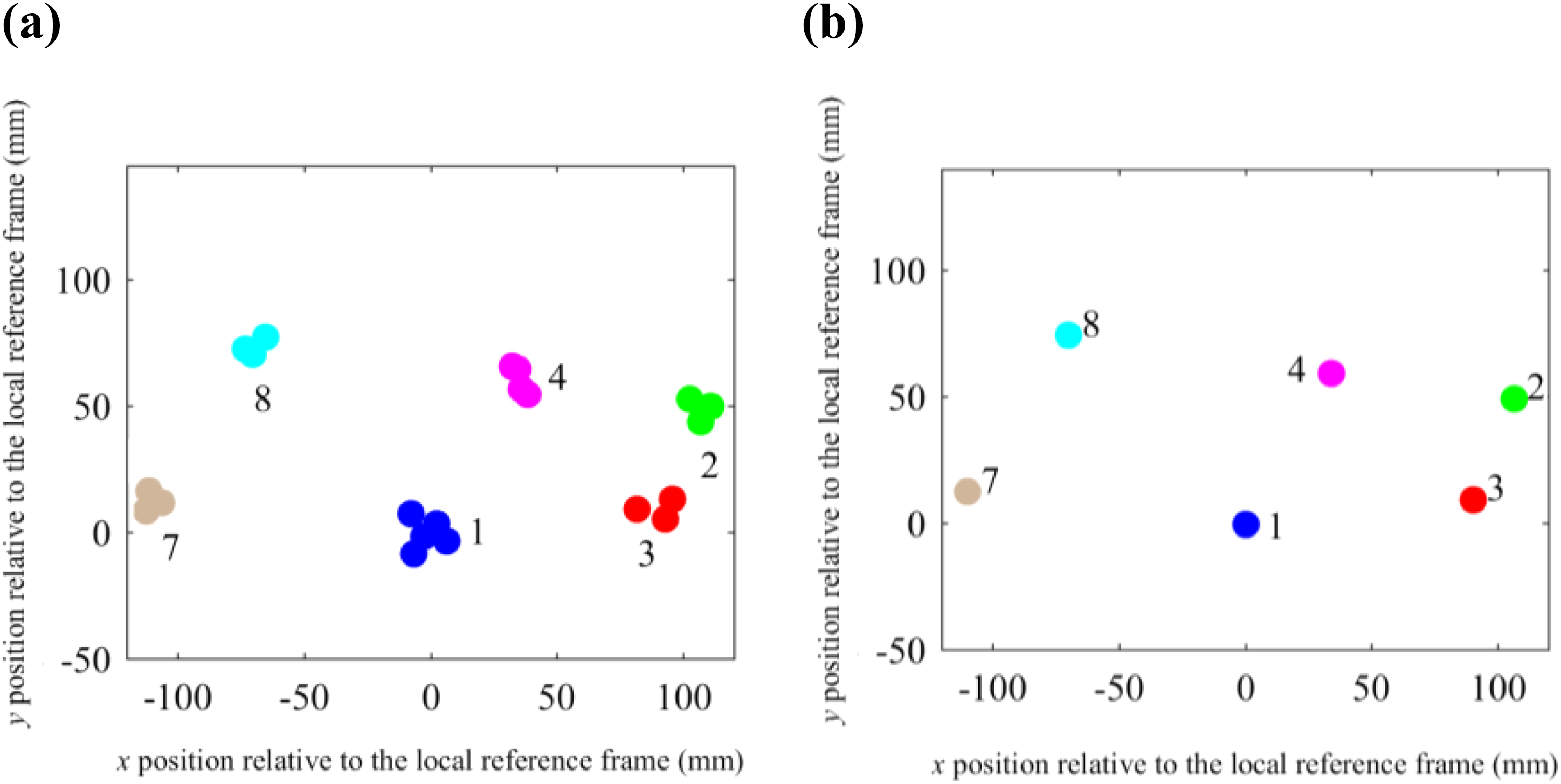
Figure 4 shows two representative data sets for a 14-robot swarm example, where each plot presents the neighbouring robots detected. One must note that relative location-data sets, acquired from individual robots, would be restricted by the accuracy and detection radii of the IR emitters and receivers on the individual robots. Figure 4(a), for example, shows the relative locations of Robots 3, 4, 7 and 8, as detected by Robot 1. All other robots are not detectable by Robot 1. Similarly, Figure 4(b) shows the relative locations of Robots 3 and 4, as detected by Robot 2. All other robots are not detectable by Robot 2. Following this process, 14 (partial) data sets are obtained, 1 per every robot in the swarm.

Visual representation of two simulated relative robot location data sets: (a) Robot 1 and (b) Robot 2.
Phase II: Swarm-topology estimation
As noted above, the proposed swarm-topology estimation method consists of two phases: (Phase I) distributed relative localization, through data acquisition from the swarm robots and, subsequent, (Phase II) global swarm-topology estimation, via a central computer. The three operations within Phase II are grouping, group-topology estimation and stitching. These were formulated similar to the three fundamental steps of divide-and-conquer approaches reported in the literature (divide, solve, merge). 76 In grouping, the robots are first divided into similarly sized sets based on robot visibility. After grouping, sub-topology estimation is performed for each group. Lastly, the central computer carries out stitching, in which the sub-topologies of all groups are combined into one global swarm topology.
Grouping
During this stage, the robots are combined into comparably sized sets through a grouping process. The approach employed is similar to the sensor-node clustering solutions reported in the literature for wireless sensor networks (refer to the work of Mahdi et al., 77 Niu et al. 78 and Abdellatief et al. 79 ). Grouping must ensure that the subsets contain overlapping robots to allow for the final stitching stage of swarm-topology estimation.
As an example, Figure 5 continues the 14-robot swarm case discussed above, where the robots are combined into three groups. In this example, Robots 2 and 3 are present in both Groups A and B, and Robots 7 and 8 are present in both Groups A and C, respectively, to allow for stitching.

Grouping of data sets.
Group-topology estimation
After grouping, sub-topology estimation (for each group) is carried out to fuse partial swarm-topology estimation data acquired from individual robots to determine the complete set of robot locations in the group. The method is novel in that it only requires partial location data sets acquired from individual robots to perform a complete swarm-topology estimation. In particular, the method performs swarm-topology estimation without any global position knowledge.
In order to fuse relative-location data, individual reference frames need to be transformed to positions and orientations in a common global reference frame. Namely, all data sets need to be superimposed and manipulated (translated and rotated), such that all respective robot data points are clustered to minimize distances between observed data points for every robot (e.g. all observations of Robot 1 should to be clustered together).
The clustering process is carried out sequentially and iteratively. Our approach is similar to ones proposed in the literature for 3D point-cloud registration 80 and template matching for object recognition. 81
For example, for Group A in Figure 5 – Robots {1, 2, 3, 4, 7, 8}, let us choose Robot 1 as the reference, the left figure in Figure 6. Next, let us superimpose and manipulate the data sets for Robots 1 and 2, the centre figure in Figure 6, followed by the superimposition and manipulation of the data set for Robot 3 on this combined 1–2 data set, to yield 1–2–3, the right figure in Figure 6. The process continues until we achieve the superimposition of all the six-robot data sets in Group A. Once this initial superimposition is obtained, the process is repeated. Namely, Robot 1 data set is retransformed and manipulated to better fit data (post superimposition) from Robots 2, 3, 4, 7, 8 and so on. The process continues until a convergence criterion is met (i.e. until no further improvements can be made) and the optimal superimposition of data sets is obtained.

Incremental superimposition and manipulation of the data sets in Figure 4.
Transformation of data sets
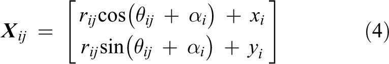
Formally, the problem of determining the optimal transform for a single data set is defined as follows: Let rij be the proximity of Robot j to Robot i, as observed by Robot i, and θij be the bearing of Robot j in the local reference frame of Robot i, then the polar coordinates (rij , θij ) denote the location of Robot j as observed by Robot i. The collection of all (rij , θij ) for a given i is called the data set of Robot i and consists of all observations of other robots made by Robot i.
Let the transformation of data set i, from the local reference frame to the common global reference frame, be defined by a rotation of the data set, by αi
, about the local reference frame origin, and a subsequent translation, by (xi
, yi
), in the x and y directions, respectively. Then, given the transformation parameters of the Robot i data set, (xi
, yi
, αi
), the Cartesian coordinates of Robot j as observed by Robot i in the common global reference frame,
Superimposition of data sets
The set of all data sets after transformation is referred to herein as superimposition. Our approach, to fuse all relative location data, is similar to the one reported in the literature for fusing multiple 3D point clouds. 82 Namely, in order to fuse the relative-location data, transformation parameters for individual robot data sets are optimized sequentially to improve the superimposition. At each optimization step, a single set of transformation parameters is selected for optimization, leaving all others fixed. Optimal transformations are the ones that minimize the distances between observed data points for every robot. Namely, the transformation parameters of Robot i are optimized to minimize the maximum distance between the coordinates of a robot as observed by Robot i and the coordinates of the same robot as observed by all other robots
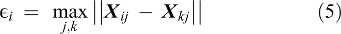
where Xij
represents the Cartesian coordinates of Robot j in the global reference frame as observed by Robot i,
As an example for superimposition, let us consider Group A robots of the 14-robot swarm given in Figure 5, where the above proposed optimization is sequentially carried out, always manipulating one data set at a time while keeping the others fixed. The optimal superimposition of the six data sets is shown in Figure 7(a). Then, the estimated robot positions are calculated by determining the mean positions of all observations for the respective robots in the common global reference frame (see Figure 7(b)).
The final estimate of sub-topology for Group (a) The optimal superimposition and (b) the final estimate of sub-topology for Group A after determining the mean positions of all observations.
The swarm-topology estimation process is repeated for every group of robots in the swarm. In our example, in Figure 5, for Groups A, B and C, the three sub-topologies obtained are shown in Figure 8.

Estimated swarm sub-topologies of Groups (a) A, (b) B and (c) C.
Stitching
After obtaining the sub-topologies for all the groups of robots, the global swarm topology is obtained by stitching these sub-topologies together, which is similar to the clustering process described above. Namely, the group topologies are superimposed in a way that minimizes cluster sizes of overlapping robots. Our optimization procedure is similar to the one described in the work of Takimoto et al., 82 as discussed above.
As an example of stitching, the sub-topologies shown in Figure 8 were superimposed and optimized to yield a global (entire) swarm-topology estimate, as shown in Figure 9.

Estimated entire swarm topology.
Experiments
In our previous work, reported in the work of Kim et al. 27,28 and Drisdelle et al. 29 , mROBerTO was directly compared to the two best robots in the field, the Kilobot and TinyTeRP, and was determined to be clearly superior in locomotion, sensing and processing performance. Thus, the experiments presented in this section focus only on validating the global swarm-topology estimation method proposed in this article. The first subsection below presents results regarding distributed relative localization (i.e. Phase I), followed by global swarm-topology estimation (i.e. Phase II) in the next subsection, respectively. We also present an experiment that demonstrates the proposed method’s application to HSI scenarios.
Phase I: Distributed relative localization
In order to illustrate the distributed relative localization performance of mROBerTO, in all experiments, the robots were placed in known topologies and allowed to localize other robots in their vicinity. The localization results were, then, compared to the true positions of the robots to assess localization accuracy.
An example
Figure 10 shows the example (true) swarm configuration with (the maximum available number of) nine physical robots. Figure 11, in turn, shows the nine sets of localization data acquired through the swarm-sensing modules of the mROBerTOs – one for each robot.

An example swarm configuration used for relative localization experiments.

Visual representation of acquired nine relative robot location data sets for the configuration shown in Figure 10.
Phase II: Global swarm-topology estimation
The proposed global swarm-topology estimation method consists of two phases: (I) distributed relative localization, and (II) global swarm-topology estimation (see Figure 3). As discussed above, the first phase is carried out using the on-board processing and sensing capabilities of mROBerTOs. The second phase begins after the centralized host PC receives the relative location data sets from the swarm robots. The experiments presented in this subsection focus on Phase II.
Group-topology estimation
In grouping, the robots are first divided into similarly sized sets based on robot visibility (i.e. robots that detect the same neighbouring robots would likely be grouped together). After grouping, sub-topology estimation is performed for each group.
Below, we first present sub-topology estimation results for several experiments that utilize our nine (physical) mROBerTOs. Next, we expand the swarm to 30 robots by including a further 21 simulated robots and carry out sub-topology estimation for this larger group. Lastly, we discuss the arbitrary order of robot consideration during the superimposition step of the proposed iterative incremental process.
Examples with physical robots
For every scenario discussed below, the swarm of nine mROBerTO millirobots is initially arranged into a known topology. The robots are, then, allowed to communicate with each other using IR to locate other robots within their respective communication range. The data of relative robot proximities acquired by each robot are, subsequently, combined (i.e. superimposed) according to the proposed (group) topology-estimation algorithm. Figure 12 shows the final estimated group topology, for Example #1, using the data shown in Figure 11, where the estimate is also compared with respect to the corresponding true positions of the robots (in purple).

The final estimated swarm topology for a set of nine physical robots shown in Figures 10 and 11.
Validation of the proposed topology-estimation algorithm is further shown here, using the nine physical mROBerTO units, for two additional different swarm-topologies. The topology shown in Figure 13(a), Example #2, has the robots arranged in a diamond shape. The topology shown in Figure 13(b), Example #3, has the robots distributed randomly. In both figures, the actual (true) robot positions are shown in purple, while the estimated robot positions are shown in green.

Swarm-topology estimation: (a) diamond-shaped and (b) random-shaped.
Dissimilarity measure
From the experiments above, it is evident that the group topology can be successfully estimated for swarms of mROBerTOs via our proposed topology-estimation method. However, in order to quantitatively measure the dissimilarity between the actual (true) and measured (estimated) shapes, a topology signature was defined in our work as the polar coordinates of all robots with respect to one reference robot, in our examples chosen as Robot 1. Figure 14, as an example, shows the successful convergence of the average dissimilarity measure for the diamond topology shown in Figure 13(a).

Average dissimilarity of the estimated swarm from desired diamond topology shown in Figure 13.
Table 1 presents the dissimilarity measure in terms of the normalized errors between the topology signatures of the actual (true) and measured (estimated) relative robot locations (r: proximity and θ: bearing) for three topologies. The minimum, maximum and average errors for each experiment are given. The normalization factor used was proportional to the radius of the swarm.
Topology-error data.
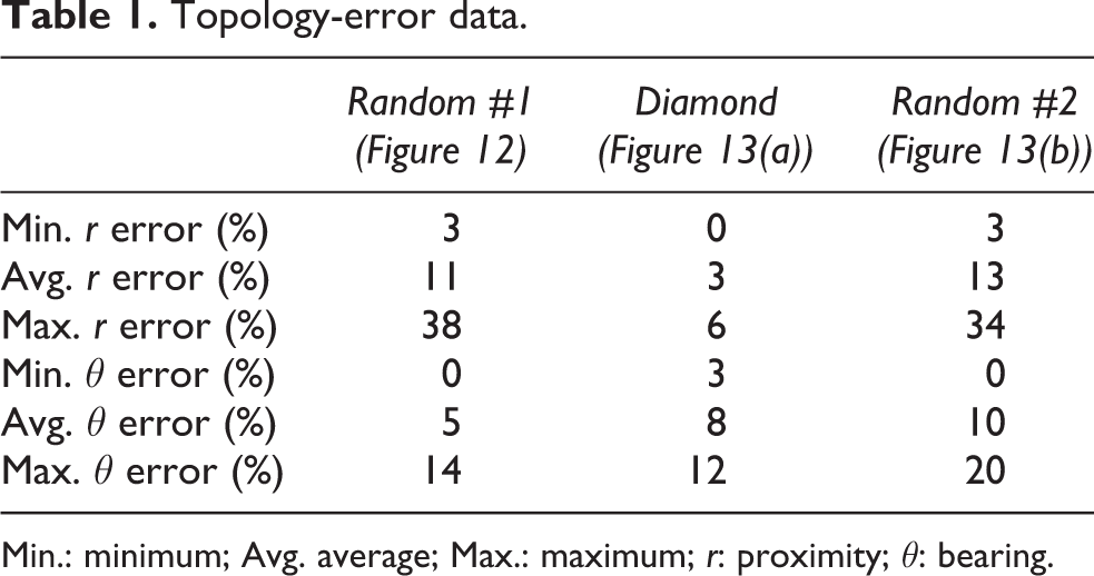
Min.: minimum; Avg. average; Max.: maximum; r: proximity; θ: bearing.
A larger scale group-topology estimation example
Validation of the proposed method’s ability to estimate the topology of a larger scale swarm is shown in this subsection for a group of 30 simulated robots. The acquired localization data for the non-physical robots included noise modelled to emulate the characteristics of real-world sensing conditions 28 for the mROBerTOs. The true and the estimated topologies for the swarm considered are shown in Figure 15.

The true and estimated group topologies for the larger scale estimation experiment.
The dissimilarity measure for this case was computed to assess the estimation accuracy (refer Table 2). The results are comparable to those obtained for the (physical) nine-robot topology-estimation experiments. Namely, estimation accuracy is not tangibly compromised by increasing the group size.
Topology-error data for the large-scale group-topology estimation experiment.

Min.: minimum; Avg. average; Max.: maximum; r: proximity; θ: bearing.
Order of superimposition evaluation
The order of robots in the superimposition step of the proposed iterative incremental process can be arbitrary, though different orders would, as expected, yield different results. In order to illustrate the (lack of) impact of superimposition sequence on the final estimated topology, the outcomes of five different superimposition sequences are shown in Figure 16.

Swarm-topology estimation, for Group A, using different superimposition sequences: (a) a 0.1% improvement threshold stopping condition and (b) 1000-iteration optimization.
Experiments were first run until less than 0.1% improvement in the objective function was observed per iteration (see Figure 16(a)). Then, the optimization algorithm was re-run for 1000 iterations to illustrate convergence (see Figure 16(b)). The results demonstrate that all sequences result in topologies that are nearly identical, which would be sufficient for a human supervisor in making decisions based on the estimated swarm topology.
Stitching
As noted above, the computational scalability of the topology-estimation algorithm proposed in this article is achieved through a divide-and-conquer approach. Namely, first, the swarm is divided into smaller groups, whose individual topologies are determined in parallel. Subsequently, a central unit combines these estimates into a global swarm-topology estimate via a mathematical operation, referred to as stitching in this article. This approach leverages the parallel computing ability of swarms to distribute the computational load across groups.
As a stitching example, a swarm of 400 simulated robots were considered. The robots were grouped into 24 different sets (refer Table 3), and the group-topologies were estimated. Subsequently, these were stitched to form the overall swarm-topology estimate. Figure 17(a) to (c) shows the results of the first three sequential superimposition steps, and Figure 17(d) and (e) shows the last two, respectively. The final swarm-topology estimation is shown in Figure 18.
Group member lists.


Sequential superimposition: (a) one group topology, (b) two group topologies and (c) three group topologies, and the last two superimpositions with (d) 23 group topologies and (e) 24 group topologies.

The final swarm-topology estimation for a 400-robot swarm.
Human–swarm interaction
The results of an additional experiment are included herein to demonstrate the proposed method’s use in HSI, where a swarm of nine physical robots (in the field) were asked to change their topology through input from a remote supervisor. Specifically, the swarm with an initial random topology (see Figure 19(a)) was instructed to reconfigure itself into a diamond shape centred about Robot 1.
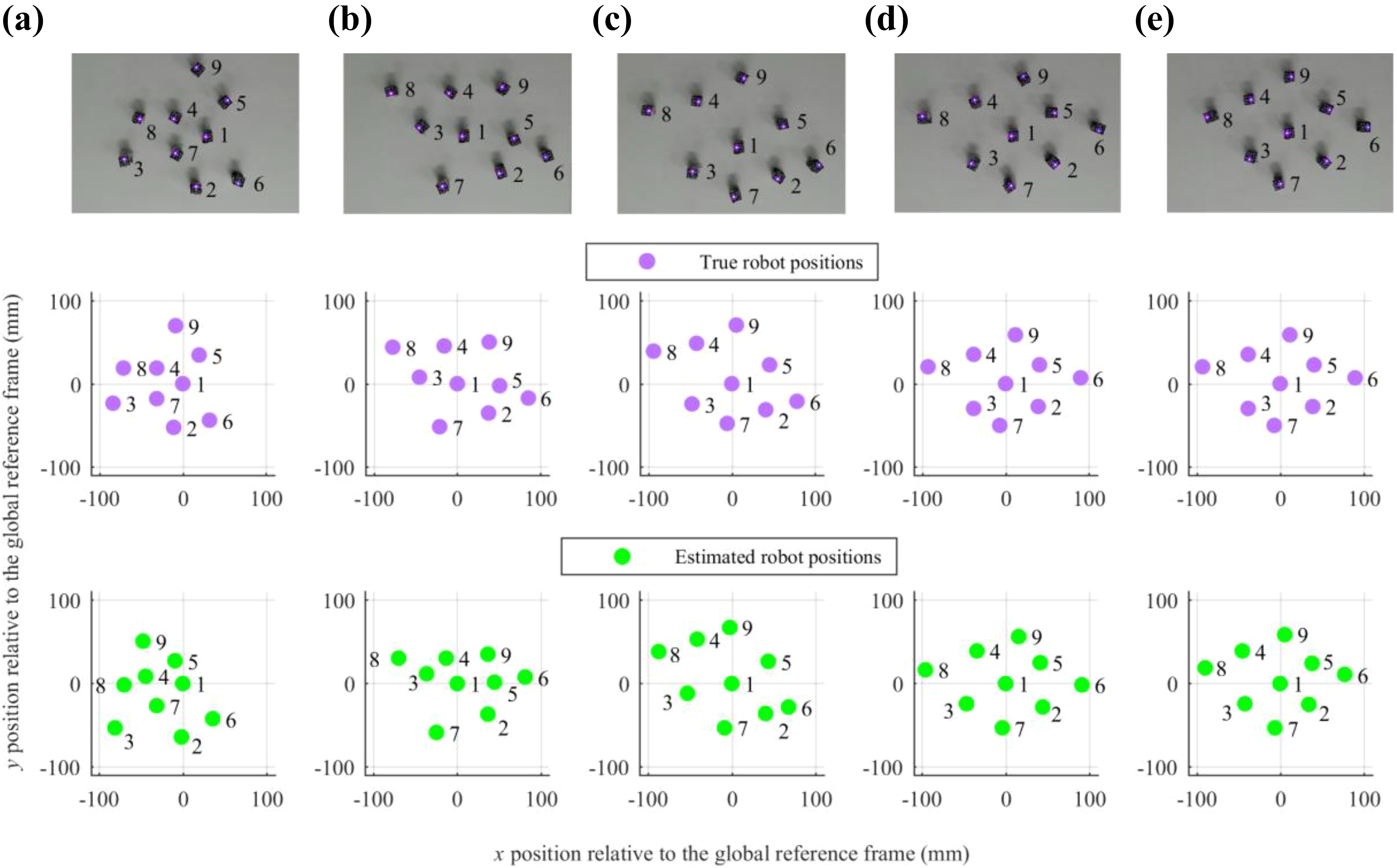
The evolution of the robot swarm over time from a random-shaped to a diamond-shaped topology.
As noted above, the remote supervisor could not directly observe the physical swarm and only had access to the estimated topology of the swarm through a graphical user interface. Figure 19(b) to (e) shows the evolution of the swarm topology, with progress from left to right. The middle row indicates the true robot positions (corresponding to the photos in the row above), while the bottom row indicates estimated swarm topologies. Swarm-topology estimation was performed at every iteration in order to provide the supervisor with up-to-date information regarding the latest swarm state.
Comparison to other topology estimation and localization methods
As noted above, the proposed method calculates a detailed swarm topology estimate using the relative positions of all the robots. This contrasts with other swarm-topology estimation methods, 72,73 which typically use summary statistics regarding the swarm. Furthermore, the proposed method achieves relative localization for topology estimation without the use of anchors or need for robot motion, as is typical in most other methods. 60 –71 Use of anchors, for example, would need the designation of some of the robots as such, requiring design modifications. Similarly, incremental movement of robots would consume valuable time.
Several methods that address topology estimation in a manner similar to our proposed method can be found in the wireless sensor network literature. 83 –85 In these cases, sensors do not move, and a map of relative positions is estimated. The most pertinent of these consider the angle of arrival of signals as well as signal strength (as a proxy measurement of range) to estimate sensor positions. 86,87 However, as in swarm-topology estimation, these methods also, typically, use anchors.
The proposed method, on the other hand, fuses incomplete data sets acquired from multiple static robots without anchors. Namely, data fusion is uniquely performed using superimposition of data and clustering of observations to obtain an estimate of the complete swarm topology. Furthermore, the proposed algorithm offloads some of the processing tasks to individual millirobots, such that the central computer carries out only high-level optimization. This contrasts with other approaches in which either raw data are processed entirely within a central computer to obtain location estimates or (limited) distributed swarm-topology estimation is carried out on a per-robot basis.
In regards to localization, mROBerTO’s swarm-sensing module achieves accuracy comparable to or better than those reported in the literature while allowing the robots to remain stationary, thus, improving the efficiency of the robots’ operation. The specific analysis reported in our earlier article 28 showed that the module’s bearing measurements had an average error of up to 10° and an average proximity (range) error of up to 5% of its maximum range. In comparison, the results presented in the work of Cornejo and Nagpal 61 had a mean squared localization error of up to, approximately, 5% of the workspace size, a root mean squared localization error of approximately 7%, depending on the noise.
A more direct comparison of our results was also made with those presented in the work of Mao et al., 62 which reported an average bearing error of approximately 5° and an average range measurement error of up to approximately 4% of its maximum range. However, the method in the work of Mao et al. 62 utilizes two robots in a cooperative manner in order to achieve the above-mentioned accuracy while mROBerTOs achieve similar results independently.
Conclusions
This article presents the design of a novel high-performance, modular millirobot, the mROBerTO. The robot design uses only commercially available components, has a minimal footprint and achieves reliable locomotion while having uncompromised sensory, communication and processing capabilities. mROBerTO is capable of IR-based proximity and bearing localization, has Bluetooth Smart and ANT+ communication capabilities and uses a 32-bit ARM Cortex-M0 central processing unit, all of which are unique to its design. These capabilities make mROBerTO a good candidate for use in complex swarm-behaviour studies, including the ability to localize the overall swarm for HSI testing.
In the above-mentioned regard, extensive experiments, utilizing physical and simulated robots, indeed demonstrated the effectiveness of the proposed global swarm-topology estimation method, including its upward scalability. Consequently, it is anticipated that our future work will aim to utilize the mROBerTOs for HSI experimentation, once sufficient progress is made on the latter front. Parallel work will also focus on improving the mROBerTO’s hardware/software. This will include upgrading the robot’s processing, sensing and locomotion capabilities.
Footnotes
Declaration of conflicting interests
The author(s) declared no potential conflicts of interest with respect to the research, authorship, and/or publication of this article.
Funding
The author(s) disclosed receipt of the following financial support for the research, authorship, and/or publication of this article: This work was supported by the Natural Sciences and Engineering Research Council of Canada and the Canada Research Chairs Program.