
Abstract
One of the limitations in the development of really soft robotic devices is the development of soft actuators. In recent years, our research group has developed a new flexible shape memory alloy actuator that provides more freedom of movements and a better integration in wearable robots, especially in soft wearable robots. Shape memory alloy wires present characteristics such as force/weight ratio, low weight, and noiseless actuation, which make them an ideal choice in these types of applications. However, the control strategy must take into account its complex dynamics due to thermal phase transformation. Different control approaches based on complex non-linear models and other model-free control methods have been tested on real systems. Some exoskeleton prototypes have been developed, which demonstrate the utility of this actuator and the advantages offered by these flexible actuators to improve the comfort and adaptability of exoskeletons.
Introduction
The use of the so-called smart materials in various areas of engineering has experienced great growth in recent years. Among these materials, our research group has specialised in shape memory alloys (SMAs). Although SMAs offer great possibilities for the development of novel sensors and actuators, their practical use presents difficulties because of their highly non-linear behaviour and their thermal activation. Focusing on soft robotics, these actuation systems have features that make them an appealing option. Their high force-to-weight ratio and small volume – SMA displays one of the highest work densities at 10 J cm−3 and is able to lift more than 100 times of its weight 1 – allow the design of compact and lightweight actuators that are suitable for soft and wearable robots, particularly exoskeletons. Furthermore, the flexibility of SMAs allows us to build actuation components in different configurations and shapes (e.g. helical springs, torsion springs, straight wires, cantilever strips and torsion tubes), which allow them to be adapted to multiple applications.
Despite these advantages, SMAs present limitations that must be taken into account in the development of actuator systems, including low actuation frequency, complex controllability and low energy efficiency. The bandwidth limitation is due to the thermal mechanisms of the SMA’s activation. The long-term stability and durability of SMA actuators depend on many factors, such as temperature, stress, strain and number of transformation cycles. In this sense, it is essential to improve control strategies to increase the number of cycles of actuation and the reliability from SMA materials. Meanwhile, low energy efficiency is an open challenge in the design of SMA actuator applications.
To extend the use of these materials as soft actuators, it is essential to develop an appropriate mechanical design and suitable control strategies to improve operational frequency, bandwidth and the durability and reliability of SMA actuators.
In this work, we summarise the research carried out from the last few years in our research group relative to the modelling and control of SMA-based actuators. Several different control approaches based on complex non-linear models and other model-free control methods have been tested on real systems. As a result of this work, a flexible SMA-based actuator has been developed that can adapt to soft or wearable robots. Finally, some robotic applications of our SMA-based actuator are presented. These applications show the possibility of using SMA-based actuators in robotics when time of response, bandwidth and energy efficiency are not critical, while taking advantage of their properties of noiseless performance, low weight and flexibility.
SMA characteristics
Shape memory behaviour materials were discovered in 1932 when A Ölander 2 observed the superelastic effect of gold–cadmium alloys. Greninger and Mooradian 3 also studied this behaviour in copper–zinc alloys. The shape memory effect (SME) was described by SJ Buehler et al. 4 in 1962 in an alloy of nickel and titanium (Ni-Ti), which he named Nickel Titanium Naval Ordenance Laboratory (nitinol). The use of SMAs has since increased in numerous technical applications, 1 mostly Ni-Ti-based SMAs.
The SME is a transformation phenomenon that is present in some metallic alloys, by which the material can return to its original form from heating over the phase transformation temperature (see Figure 1). This effect is due to the transformation of the crystalline structure of the SMA. Furthermore, SMAs can exist in an austenite crystalline structure, which is stable at high temperatures, and a martensite structure, which is stable at lower temperatures. The SME phenomenon can either be a transformation between low temperature phase (martensite) and high temperature phase (austenite) or a reorientation among different martensite variants. When an SMA material is heated, it begins to transform from martensite into the austenite phase and it then contracts. This contraction occurs even under high applied loads, resulting in high actuation capability. A subsequent cooling of the material converts the austenite back into martensite and the internal stresses of the material return it to its original shape. Thanks to this effect, SMA materials can be used as actuators that are capable of converting energy into mechanical work. The deformation–recovery cycle of Nitinol can be repeated millions of times, provided that the applied deformations are in the recovery range of the alloy, thanks to its superelasticity feature. 5 A fundamental characteristic of the SMAs is the thermoelastic nature of these transformations, which implies that they can either be induced by a change in temperature or by external stress applied to the material.
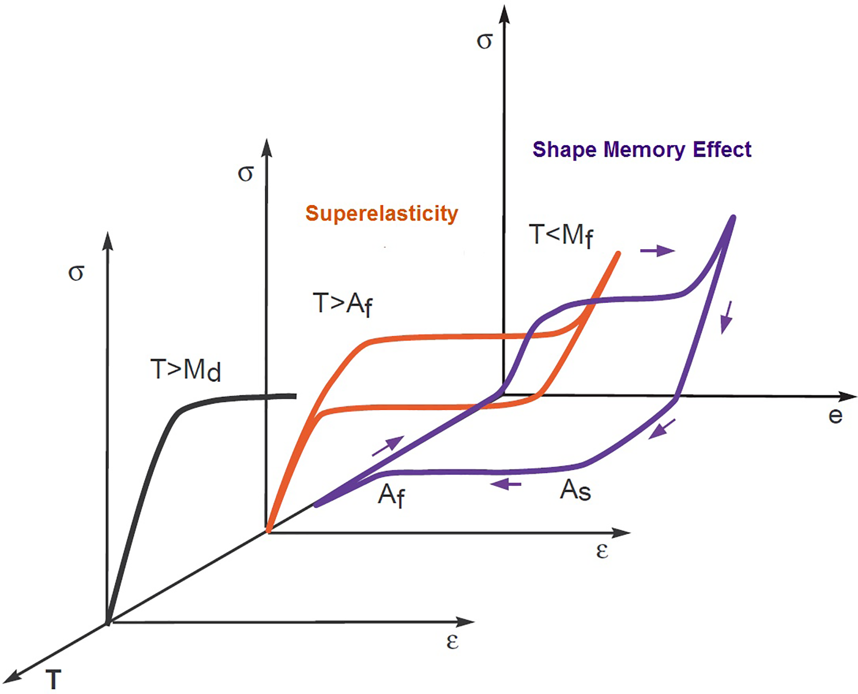
Effects on SMA according to temperature and stress. SMA: shape memory alloy.
These properties can be used in a wide spectrum of applications, which include the generation of forces or movement (taking advantage of shape memory) and energy storage (taking advantage of superelasticity). However, it must also be considered that, from a macroscopic point of view, this change in crystalline structure causes the modification of other physical properties, such as thermal conductivity, thermal expansion coefficient or resistivity.
In a heating–cooling cycle (see Figure 2), there is a hysteresis type of change in the properties. During the heating process, the SMA begins to transform from martensite into the austenite phase at the As temperature, and the transformation is complete at Af temperature. However, during the cooling process, the transformation starts to revert to the Ms temperature and is complete when it reaches the Mf temperature. These transition temperatures characterise the hysteresis loop and they depend on the composition of the SMA material and the applied stress.

Hysteresis loop of SMA materials. SMA: shape memory alloy.
SMAs may be heated up by several different methods, but, for small diameter SMA wire, the most common method is to pass an electrical current through them. With a simple circuit that applies an electric current to the SMA, the SMA element is heated by means of the Joule effect. Two transduction processes take place. First, electric energy is transformed into thermal energy thanks to the Joule effect. This thermal energy triggers the shape recovery process of the SMA element, and the resulting recovery energy is transformed into mechanical work. The bandwidth of SMA actuators is usually limited, while the cooling speed is the dominating factor. As thermally activated actuators, their actuation speed mainly depends on the cooling time of the SMA element, which is strongly influenced by the process of heat convection from the SMA to the environment. Cooling and heating speed also depend on the size and shape of the SMA actuator: Actuators with smaller diameter heat more quickly due to their higher resistivity, and they cool more quickly due to their higher surface-to-volume ratio.
The actuation bandwidth can be improved by passive methods, such as heat dissipation or active methods such as airflow circulation or liquid cooling. Another well-known issue of SMAs, and one of the main research topics within the field of SMA actuators, is their non-linear behaviour, which affects their controllability. The reason for this non-linear operation is that the temperatures at which the transformation from martensite to austenite takes place are different from the ones of the austenite to martensite transformation, giving rise to thermal hysteresis. 6 For technical applications, the hysteresis SMA property is very important and must be carefully taken into account for control objectives. In general, for robotic applications, small hysteresis is required.
The long-term stability, durability and reliability of SMA actuators must be assured when they are subjected to multiple transformation cycles. This depends on many factors, for example, where thermal effects are more relevant, overheating the SMAs reduces the number of cycles of life, and hence the SMA actuator temperature should be controlled. Furthermore, it is essential to select the appropriate working boundary conditions to obtain high reliability from SMA materials. Consequently, overstressing and overstraining should be prevented to guarantee the applications for long durations.
Among the SMA materials, Nitinol has properties that have made it the most widely used SMA material in technical applications. Since the 1980s, the commercial application of NiTi alloys has developed in many areas thanks to the greater demands for lighter and more compact actuators, especially in biomedicine. 1 However, it is still necessary to investigate to improve the characteristics of these actuator systems, mainly increasing their bandwidth and stability. To use actuators based on SMAs in robotic applications, it is necessary to improve the mechanical design of the actuators and the controller systems. SMA material modelling is the first step to develop suitable control strategies.
SMA modelling
Thermo-mechanical models are very useful when it comes to predicting the complex response from a thermo-mechanical point of view of materials with shape memory. The thermo-mechanical study of these materials focuses on their free energy function and the dissipation potential. Several different models have been developed for the characterisation of the behaviour of these materials.
However, there are strong differences between these models, such as the scales at which the phenomena that occur in the SMA material are modelled. 7
Undoubtedly, from an engineering point of view, it is the macroscopic behaviour of the material that is most interesting because it can achieve a concrete application and, therefore, macroscopic models are of greatest interest. This article presents the development of two types of SMA wire models for use in the development and syntonize of control algorithms: hysteresis models and a black box model for the SMA wire.
Hysteresis model
Our research relative to SMA modelling begins with the hysteresis model problem. Martin-Clemente 8 developed a novel methodology for identification, adjustment and implementation in the control loop, which improved the conventional linear methods. In this work, various hysteresis models for SMA wires were compared. Hysteresis models can be classified into two large groups: physical models, which are based on the physical principles that govern behaviour of the system; and phenomenological, which are designed to produce similar behaviour to real systems but without the need to know or consider their physical details.
Several methodologies are used to model these hysteresis behaviours with phenomenological models, including models based on differential equations, such as Bouc–Wen model, and model based on operators, such as Prandtl–Ishlinskii. These two models are used in this work to identify hysteresis behaviour in SMA actuators, which will be presented next.
Bouc–Wen model for SMA wire
This type of model uses differential equations to approximate the behaviour of systems with hysteresis. The Bouc–Wen model is characterised by being very versatile and capable of describing a large number of patterns of hysteresis.
Considering a physical system, with a hysteresis component that can be represented by a map


The behaviour of the Bouc–Wen model is not described by a single set of parameters

where z 0 is the maximum value of the measurable output. Then, the Bouc–Wen model can be represented by

Once the model has been expressed with only five variables, the task of identifying the five parameters that completely define this new normalised Bouc–Wen model is much simpler.
In this work, we will define the parameters that make up the Bouc–Wen model through non-linear optimisation techniques that adjust the experimental model to the theoretical model. Of all the methods of optimisation, the one that will be applied is that of differential evolution (DE), 9 which belongs to the category of evolutionary computation. All evolutionary algorithms evolve until the minimum cost value of the cost function is reached. The design of this function determines the performance of the optimisation but, in all cases, it represents the error of similarity between both sets of points. This method is based on a population that represents a hysteresis model through a set of five parameters. Meanwhile, this set is defined as a member of the population.
To determine the five parameters of the model, an SMA wire with a diameter of 0.13 mm, temperature of activation in 90°C, the length of wire 0.23 m was used and a maximum current of 0.32 A was applied. After setup on the test bench, the following identification methodology was proposed: Choice of a suitable work signal to reach the permanent regime, where the hysteresis cycle is repeated identically. Determination of the SMA work frequency. Once the signal has been applied for several cycles until it reaches a stable cycle, the data corresponding to the hysteresis output that is being measured from a complete cycle (rise and fall) will be extracted. Application of the DE algorithm to obtain the parameters.
The result of the model identification is represented in Figure 3, where the x-axis represents the applied intensity and the y-axis represents the deformation.

Evolution of the optimisation algorithm for the Bouc–Wen model. Figures represent deformation (%) versus applied intensity (A): (a) real cycle, (b) first iteration, (c) 10 iterations, and (d) 60 iterations.
The identification is not very accurate at the saturation ends of the SMA wire. Unsaturated cycles are better suited to the model. These results were obtained with just 100 iterations of the optimisation algorithm. From this point, the results were not improved.
Prandtl–Ishlinskii model for SMA wire
Operator-based models attempt to reproduce behaviours that are similar to those observed in physical systems but without a specific knowledge of their physical laws. The general idea is to model non-linearities with a weighted superposition of operators of simple hysteresis operators. Among the operator-based models, our group developed a Prandtl–Ishlinskii model that can be applied to describe SMA wire behaviour. The Prandtl–Ishlinskii model is based on the superposition of elementary operators. It uses the play operator as the basis for modelling any hysteresis, although through some modification, it can describe complex features such as saturation or frequency dependence. The play operator is represented by equation (6)

Depending on the number of operators, many hysteresis loops could be described (see Figure 4).

(a and b) Hysteresis operator play type and Prandtl–Ishlinskii model with 20 operators.
To reflect the properties of non-symmetry and saturation of SMA hysteresis, the generalised Prandtl–Ishlinskii model is used with envelope functions that capture the saturation effect. The density functions, thresholds and mainly the envelopes used for both the loading part and the discharge of the actuator must be adjusted.
The Prandtl–Ishlinskii n-operator model is represented by equation (7)

where the play operator,

The Prandtl–Ishlinskii model is largely determined by the choice of envelope functions. It is necessary to find some functions that resemble the properties that you wish to reflect in the modelling. SMA-type actuators have, among many other characteristics, saturation from a certain temperature value. Conventional envelope functions do not reflect this behaviour and, therefore, will not work correctly at the control ends. Consequently, another suitable function is necessary for this purpose. In the SMA modelling, the envelope function proposed is (see Figure 5)

where

Hysteresis tanh operator.

Evolution of the optimisation algorithm for the Prandtl–-Ishlinskii model with 10 operators type tanh: (a) real cycle, (b) first iteration, (c) 10 iteration, (d) 20 iterations, (e) 50 iterations, and (f) 400 iterations (black) on the real cycle (blue).
Black box SMA wire modelling
Given the peculiarity of these SMA-based actuators, a modelling procedure that provides consistent results can be used to model the SMA wire performance in two parts or stages: the contraction stage (heating stage) and the recovery stage (cooling stage). This division has been done according of the characteristics of the material – in the contraction stage, the actuator requires the input signal, as represented by the power supply signal; and in the recovery stage, the actuator does not present the input signal and depends instead on the recuperation force, diameter of the wires and ambient temperature. 10
The estimated SMA wire model has been done according to the input/output signals, using non-linear models based on Hammerstein–Wiener and non-linear autoregressive exogenous (NARX) model models. 11
Hammerstein–Wiener model
This model is based on a combination of a linear and non-linear systems with a transparent relationship between them, which makes it easier to implement than other non-linear methods. 12 This model is composed of one linear block (a discrete transfer function) and one or two non-linear blocks (see Figure 7). 13

Structure of the Hammerstein–Wiener model.
In Figure 7, the structure of the Hammerstein–Wiener model is composed of two non-linear blocks and one linear block. The first block represented by
NARX model
The NARX model is a dynamic recurrent neural network (the static network does not present feedback and delays) with feedback connections that enclose several layers of the network. This model can be stated algebraically as

where the output y(t) is regressive to previous values of the output signal and previous values of the input signal. It is common to add an error signal to the NARX model, as denoted in equation (10) by εt, which is a term that can represent a necessary error or deviation so that the time series (y(t) and u(t)) can more accurately predict the desired output for the plant being modelled.
Figure 8 shows the neural networks NARX scheme. 13

NARX, two-layer feedforward network.
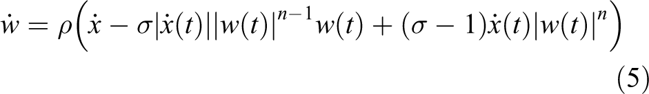
For the SMA actuator identification, based on these two models, the input/output signals were required. In this regard, an input signal was introduced to the physic system, and the behaviour of this output signal was saved. The input signal was represented by the steps whose amplitude and longevity in time causes the actuator to reach about 4% of its contraction, which represents the maximum commonly recommended when working with this type of SMA wires. Figure 9 shows the input/output signals according to which the actuator model was estimated. The results are represented in Figure 10. The total approximation between the identified model and the real model is about 99.28%.

Input/output signals.

Estimated model.
For the SMA actuator’s contraction movement (heating stage), the input and output signals were saved. The estimation was done for two actuators type: with diameters of wires of 0.15 mm and 0.5 mm and displacing a variable weight (force). The ambient temperature for all the models was 19°C and the length of the actuator 0.23 m. The activation temperature of the used material, Nitinol, is 90°C. For each combination force–diameter of the wire and in function of the datasheet characteristics, a model was estimated based on either the Hammerstein–Wiener or NARX models. The final model is composed of a concatenation of these models.
The principal problem of this type of actuator is represented by the cooling stage, where the SMA material recuperate the initial shape. The input data in this case are missing, and the actuator recovers the initial shape with the temperature change and the necessary force for shape recuperation, and only the output data are saved. According to these data (without input data), it is impossible to estimate a model with Hammerstein–Wiener or NARX. In this case, the model was estimated with the aid of the curve fitting toolbox of MATLAB. The number of the recuperation movement models estimated coincide with the number of contraction movement models.
Performance and results
The identified model has been developed in MATLAB/Simulink, a simulation programme, which can easily be integrated with other MATLAB/Simulink programmes for complex simulation. This permits us to develop control algorithms based on SMA actuators for rehabilitation device and test them in simulation before to test in the real devices.
The final structure SMA actuator model, implemented in MATLAB/Simulink, can be seen in Figure 11. This model includes a preload function which imports the black box models of the SMA actuator with different identification characteristics. The model block as shown in Figure 12, which simulates the behaviour of the SMA, has a mask where the user can choose the weight necessary for the initial shape recuperation and the diameter of the SMA wire. In the interface, two types of SMA actuators can be chosen: with a diameter of 0.15 mm and 0.51 mm, respectively, from Dynalloy. 14 Both have an activation temperature of 90°C.

SMA model interface in MATLAB/Simulink. SMA: shape memory alloy.
SMA model in MATLAB/Simulink. SMA: shape memory alloy
The recovery weight can be chosen depending on the SMA wire diameter: from 0.1 kg to the maximum weight accepted by the wire. For example, for a wire with a diameter of 0.15 mm, the value of the recovery weight goes from 0.1 kg to 0.5 kg. The results where the model response is compared with the real actuator response can be seen in Figure 13, where the main parameters of the tested SMA wire are as follows:
diameter:
length:
recovery mass

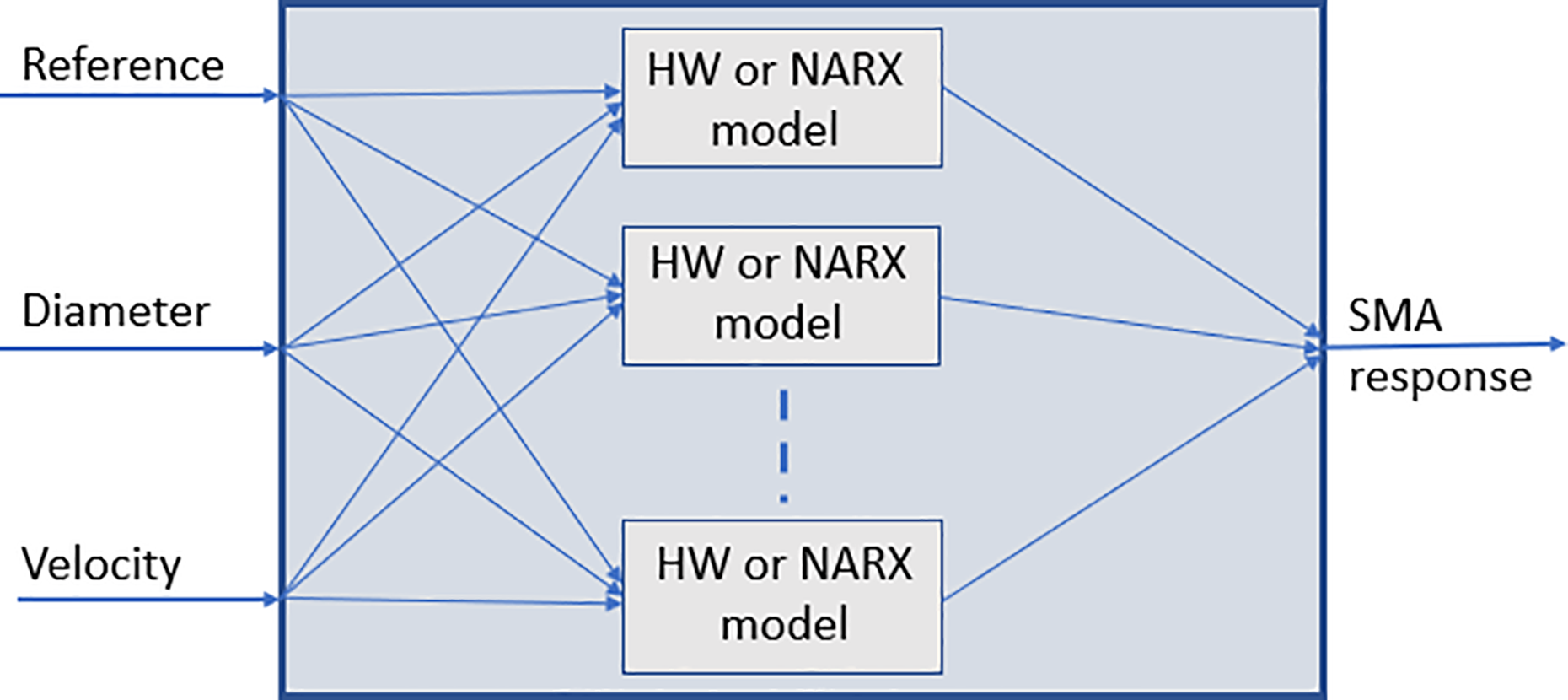
Response of SMA actuator model compared with the real response of the SMA actuator (diameter
As can be seen in Figure 13, the simulated model has a very similar behaviour with the real model, with a minimum error (the difference between the two responses). The differences between the simulated model and the real model are caused mostly by friction between movable parts of test bench mechanical structure. Moreover, in the cooling stage, where the model is estimated with the curve fitting toolbox because the input signal is missing, the simulated model presents a very similar behaviour with the real model’s response.
A second test has been performed that compares the response of the SMA actuator model with the response of the real actuator using an SMA wire with a diameter of

Response of the simulated SMA actuator compared with the real one with
For this second test, the error between the simulated model and the real model can be seen in Figure 15. Most of the time, the error does not exceed 10 µm. The square error for this test has been 3.59 µm.

Error between the simulated model and the real model.
In Figure 16, the response of the SMA actuator model when tracking a step position reference can be seen. When maintaining a fixed position, the behaviour of the SMA presents small oscillations around the reference. This behaviour occurs to a lesser extent in the real actuators but is exaggerated in the identified model. The closest behaviour between the identified model and the real actuator has been obtained with a 5 mm reference using an SMA wire with a diameter of 0.51 mm and a weight of 1 kg and a wire with a diameter of 0.15 mm and a weight of 0.5 kg.

Simulated SMA response following step reference. SMA: shape memory alloy.
The response of the modelled SMA actuator tracking a sine wave reference is shown in Figure 17.

Simulated SMA response tracking a sine reference. SMA: shape memory alloy.
Control strategy
The main difficulty when controlling SMA-based materials is their saturated hysteretic behaviour, which appears during martensite–austenite and austenite–martensite transformations. This introduces non-linear behaviours into the system, which makes it difficult to develop control algorithms for this type of actuator. Many different strategies can be applied to control non-linear systems. Nevertheless, not all of them are appropriate for systems with hysteresis. In SMA actuators, this hysteresis cycle is not exactly known but it can be approximately modelled using different methods, as shown in the previous section.
The controllers vary from simple linear controllers to more complex non-linear control approaches. Due to the complex behaviour caused by their hysteresis cycle, SMA actuators are mostly controlled using non-linear methods. Different procedures can be followed when addressing the problem of modelling and controlling the behaviour of systems with hysteresis. Regarding the techniques applied to SMA actuators, these methods will be divided here into model-based controllers and inverse model controllers.
Model-based controllers: The controller is designed based on the equations of the system. Representative models of SMA wires are used. The most important difficulty of this type of controllers is to obtain accurate models.
Inverse hysteresis model controllers: The compensator is based on an inverse hysteresis model. In the first step, a hysteresis model is built based on the experimental data of the system. The hysteresis model is designed to minimise the error between the real system and the model. In the second step, an open-loop controller in which the inverse operation adjusts the actuator input to compensate the hysteresis of the system is implemented.
The techniques that use hysteresis model can be classified into two groups:
Black box-based controllers: The hysteresis is modelled as a black or grey box. They exploit the universal approximation properties of neural networks, fuzzy systems and neuro-fuzzy structures. These methods require a large amount of experimental data.
Phenomenological-based controllers: The hysteresis is modelled by phenomenological hysteresis modelling methods. Prandtl–Ishlinskii models have been used. Accurate results are obtained using the inverse of these phenomenological hysteresis models as a feedforward compensator.
Pulse width modulation (PWM) controllers are used in a wide variety of problems. In the context of SMA, actuators have shown to be an effective solution in position controllers of SMA actuators to reduce the energy consumption by the actuator. The controllers that have been developed in this work are PWM controllers.
The control strategies that have been tested in this work to control SMA wires are presented in this section. First, results of the proportional–integral–derivative (PID)-based control Figure 18 technique have been tested with Bouc–Wen and Prandtl–Ishlinskii models. 8 In this section, we summarise the proportional derivative proportional integral (PPID) and bilinear PID (BPID) control approaches proposed by Flores et al. 15 and Villoslada et al., 6 respectively.

PID control scheme. PID: proportional–integral–derivative.
PID controller with Bouc–Wen model
Once the five parameters of the standard Bouc–Wen model have been identified, a control strategy based on a PID regulator is proposed. The parameters of this will be calculated accordingly. 16 This method applies the following control set point to assign a value to the intensity (modulated in pulse width) applied to the SMA at each instant of time:

With the new adjustment of the PID provided by the identification carried out, Figure 19 is obtained.

PID control with SMA Bouc–Wen model. PID: proportional–integral–derivative; SMA: shape memory alloy.
Control methodology using the Prandtl–Ishlinskii model
In this strategy, a feedforward compensator is designed for its implementation in the control loop of the system. To implement this model in the control loop, we proceed to the methodology of the hysteresis compensator in feedforward term, by means of the inverse model to which a PID controller is added, see Figure 20. By inverting the Prandtl–Ishlinskii model, an intensity in feedforward term is achieved that minimises the effects of hysteresis in the model.

Feedforward compensator control scheme.
In the case of the Prandtl–Ishlinskii model with non-linear envelope function (tanh), the follow-up is shown in Figure 21.

Control of Prandtl–Ishlinskii + PID with tanh envelope function. PID: proportional–integral–derivative.
PPID controller
The control strategy presented by Flores et al. 15 uses a commuting strategy that switches between two controllers: a proportional–derivative (PD) controller and a feedforward plus proportional–integral (ff + PI) controller. The general idea is to use different controllers for the heating phase and for maintaining the reference: the first controller is used in the transient regime and the second controller is active in the permanent regime. The output of the controller is converted to a PWM signal that regulates the current flowing through the SMA wire. This control architecture is shown in Figure 22. The PD controller is C PD and the PI regulator is given by C PI. C FF represents the offset introduced by the feedforward component.

PPID control scheme.
The controller switches automatically between the PD and the ff + PI controllers depending on its input and sensor signal (actual position). If the error (difference between the actual position and the desired reference) is around 0, the feedforward-PI control is active in other case, when a new position reference is given to the controller and the actuator must contract or expand to reach this new position, it switches to PD control. The feedforward term of the controller applies a small current to preheat the SMA wire to achieve a small contraction. When the wire expands, the preheating current given by the feedforward term is not applied.
BPID controller
In Villoslada et al., 6 a four-term bilinear PID (BPID) Figure 23 control strategy was successfully applied to control a single SMA wire. Based on this work, a simple four-term BPID controller was proposed and used successful to control SMA actuators in the work of Copaci. 12 The BPID controller is a combination of a standard linear PID controller cascaded with a bilinear compensator.

BPID controller scheme. BPID: bilinear proportional–integral–derivative.
The control signal generated by BPID controller is a PWM signal, which is provided by control hardware architecture. The percentage of PWM signal is modulated according to the error signal. When the error is maximum, the PWM signal achieves 100%. This signal is reduced if the error signal decreases. Therefore, PWM signal controls the current supply of SMA actuators. The PID controller is used to send a PWM current (I) to the actuator. The gains of the BPID controllers were experimentally set.
The response of the controlled system provided by the position sensors was compared to the desired reference. Figure 24 shows the position desired reference and the SMA response. It can be observed that the output follows the reference (the steady-state error is zero) and the system presents an overdamped response. The test was done with SMA wire from Dynalloy Company with a diameter of 0.51 mm, at ambient temperature 20°C.
Response for the BPID controller tracking a step reference. BPID: bilinear proportional–integral–derivative.
SMA-based actuator
In the last decade, SMA-based actuators have sparked the interest of many researchers due to its promising characteristics: very good force/weight ratio, simplicity, low weight and small size, which make them ideal to replace pneumatic, hydraulic or solenoid actuators. The actuation system designed by our research group is based on the flexible SMA actuator presented by Villoslada et al. 17 In this work, the alloy used is Nitinol and the Nitinol SMA wires are heated by means of the Joule effect.
The model and control algorithms that have been presented in previous sections have allowed us to obtain an actuator with good characteristics in relation to the durability and reliability.
A high-strain flexible SMA actuator has been designed based on the principle of Bowden cable actuation, which makes it possible to bend the device. The designed actuator has a great potential to be used in soft wearable robots. The proposed design achieves a great linear displacement compared to the total length of the actuator.
The proposed actuator is formed by one or more SMA wires, Bowden cable, polytetrafluoroethylene (PTFE) tube, and the terminal parts (Figure 25):
The Bowden cable is a mechanical flexible cable, which consists of a flexible inner cable that forms a metal spiral and a flexible outer nylon sheath. This type of wire can guide the SMA actuators and transmit the force. In addition, the metal has the property of dissipating the heat, which is an interesting advantage during the recuperation of the initial position phase.
The PTFE tube can work with high temperatures, more than 250°C, it is an electrical insulator and it does not cause frictions.
The terminal units are used in one end to connect the actuator to the actuated system and in the other end to fix the SMA wires to the Bowden cable. They also serve as connectors for power supply (using the control signal). These units are formed by two pieces that can be screwed to each other to set the tension of the SMA wires. The total SMA wire tension range adjustment is 0.01 m.
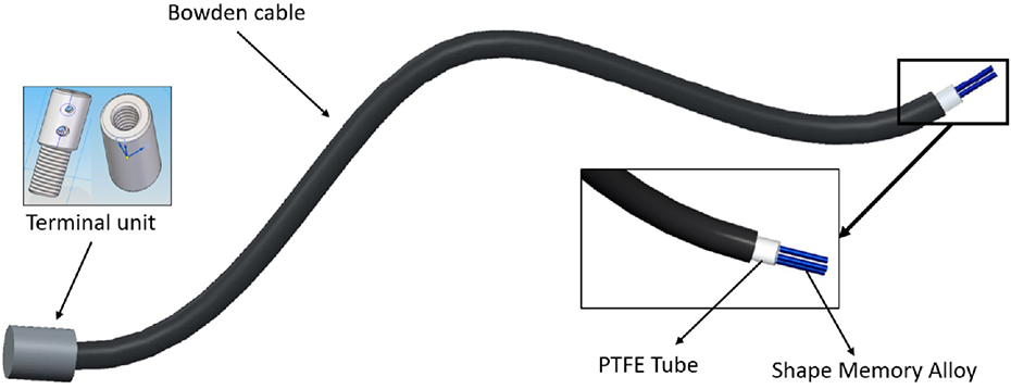
Flexible SMA-based actuator. SMA: shape memory alloy.
The main field of application of this flexible actuator is wearable robotics; more specifically, soft exoskeletons and robotic prostheses, where weight reduction is a major design factor and where large displacements and forces are required. Its main feature is that it is a flexible actuator: it can be bent and still be able to transmit force and motion. This feature allows to overcome one of the limitations of SMA actuators (i.e. the limited displacements they can produce) using a long SMA wire that can be bent to fit the shape of the structure in which the actuator is installed, without limiting the motion of the structure, even if it is articulated and changes its shape dynamically. This allows for a better integration and adaptability than other existing high-displacement SMA actuators.
Flexible SMA actuator applications
One of the main purposes of the designed flexible SMA actuator is its application in soft wearable robots. Because of the limited time response of SMAs, its use in actuating soft exoskeletons is restricted to those devices that do not require high actuation rates. The feasibility of using the presented actuator in rehabilitation-oriented soft wearable robots has been demonstrated with the design of different prototypes for upper limb exoskeletons. This flexible actuator has been used for the development of elbow rehabilitation exoskeleton presented by Copaci et al. 18 and wrist exoskeleton in Serrano del Cerro et al., 19 thanks to the use of the SMA actuator, these devices have the advantage of lightweight and noiseless performance.
The prototypes that best fit the definition of soft robotics are presented below. In Figure 26, a wrist mobilisation prototype device driven by the flexible SMA actuator is shown. This wrist exoskeleton is intended to actively actuate the extension movement of the wrist, while the flexion movement to a neutral position is passive. Being a soft exoskeleton, the structure of the device does not consist of rigid links joining the forearm with the hand, and there is no rotational joint parallel to the sagittal plane of the wrist; it only has a few rigid parts, which are intended to fix the actuator ends. This greatly reduces singularities in the workspace of the device, improves kinematic compatibility because there is no joint misalignment and the device is more adaptable to different users’ body sizes, more comfortable and more portable than standard rigid solutions. To mobilise the hand and thus extend the wrist, the movable end of the actuator is crimped to a simple rigid piece that is placed over the wearer’s hand. When the SMA wire is contracted, this piece is pulled and the extension of the wrist is achieved.

Wrist exoskeleton prototype: arrangement of the flexible actuator around the arm.
The soft robotics wearable elbow exoskeleton presented by Copaci et al. 20 can be seen in Figure 27. This preliminary design of wearable elbow exoskeleton actuated with SMA-based actuators (without motors) allows for the drastic reduction of the weight of the exoskeleton (about 0.6 kg) and achieves a quiet operation characteristic that increases the comfort and portability of the system. The proposed design of the exoskeleton does not use rigid components for the articulation motion, using the rotation centre for proper patient elbow joint articulation. Trial with this prototype has been carried out on a male (1.8 m height, 80 kg weight, 23 years old); with these characteristics, its right arm weighs approximately 4.5 kg. The SMA actuator for this application is built with n = 3 wires. It can perform the flexion–extension movement for the elbow joint considering a range of movement from 0° to 150°. Considering that movement range, the contraction distance needed is around 7.5 cm, so the SMA wire length is about 1.85 m. As the exoskeleton is built for flexion–extension elbow medical rehabilitation, the degree of freedom for supination–pronation must be cancelled, so the patient’s wrist is blocked. To measure the exoskeleton angular position, a flex sensor by Spectra Symbol Salt Lake City, UT 84119 has been used. The sensor is positioned over the elbow joint with the aid of the arm covering. The sensor signal is used as feedback for the control loop.

Soft wearable elbow exoskeleton.
This type of SMA flexible actuator and the control technology presented in this article has been used in the development of a wearable actuated device for extravehicular activities (EVA). The device presented by Villoslada et al. 21 aims to tackle one of the problems that astronauts face during spacewalks: hand fatigue due to the pressurised EVA gloves. Consequently, as part of the EU-funded STAMAS project, a soft hand exoskeleton called Hand Exo-Muscular System (HEMS) has been developed to assist astronauts during EVA missions.
To mitigate hand fatigue and the other hand-related problems that arise during EVA missions, the proposed solution releases the astronaut from exerting all the force needed to mobilise the fingers when wearing an EVA glove by means of the HEMS (Figure 28). This soft exoskeleton is intended to be embedded into the spacesuit glove, and its purpose is to exert part of the force needed to overcome the rigidity of the glove by counteracting the opposing forces caused by the inner pressure.

Hand soft exoskeleton prototype.
This system can be defined as an exomusculature designed according to the soft exoskeleton design paradigm without external rigid structure. The central element of the HEMS is the actuation system, which consists of six flexible SMA linear actuators connected to the fingers through a series of artificial tendons that assist the user in flexing the fingers. Although there is no rigid structure in a soft exoskeleton, some kind of support element is required. In the case of the HEMS, the suit structure is the element that provides mechanical support and fixation points for the actuation system, sensory system and control hardware. It is composed of a body harness, a forearm elastic sleeve and a glove.
The glove is the most important element of the suit structure: It is the mechanical interface that transmits the forces generated by the actuators to the user’s fingers. The actuators are connected to the glove through a series of inextensible cords attached to the fingertips and routed through the underside of the fingers and the palm of the glove. This artificial tendon system transmits the force and linear motion of the actuators to the fingertips of the glove, thus helping the user to flex the fingers. The index, middle, ring and little fingers have only one tendon each, while the thumb has two tendons: one attached to the tip to perform the flexion movement and a second attached to the base of the thumb to perform the abduction movement. This arrangement makes a total of six actuated degrees of freedom. To fully flex the user’s index finger with the HEMS, a linear displacement of 5–6 cm is required, which, with the SMA contraction limitation, implies the use of a 2-m long SMA wire. To avoid using such a long wire, a simple pulley interface connects its moving end to its corresponding artificial tendon of the transmission system. This pulley doubles the displacement of the SMA element, hence a shorter wire is used. Using this displacement multiplier mechanism, the length of the wire used in the actuator has been reduced to 90 cm. The HEMS sensory system is composed of three different types of sensors: linear position sensors to measure the output displacement of the actuators, force sensors to measure the force exerted by the SMA wires and pressure sensors to measure the force exerted by the user.
Conclusions
To use SMA-based actuators in soft robotic devices, the development of suitable control algorithm is essential. This article presents the results obtained with different control approaches for SMA wires. Regarding the control strategy, the implemented control algorithm based on BPID control scheme is able to make the actuator follow different references with an acceptable accuracy when controlled both in position. The controlled actuator shows no overshoot nor does it limit cycle in the case of stationary references, and the oscillation around the set point when following continuously varying references is minimal. Thanks to this control algorithm, it has been possible to overcome some of the problems that this type of actuator initially presented. With the proposed control algorithms and mechanical designs, the long-term stability and durability of the SMA-based actuator are not a disadvantage for their use. The only limitation lies on its actuation speed imposed by the cooling time of the SMA wire. Despite the improvement in the actuation frequency, the actuator speed is still somewhat reduced for slow tasks.
The flexible SMA actuator design based on the Bowden transmission system certainly has some features that make it a potential alternative to the use of conventional actuators in soft exoskeletons because it solves some of the limiting factors of SMA actuators. The possibility of using long SMA wires inside a flexible body makes it feasible to design an actuator that is able to provide the large displacements often required by soft exoskeletons, and which is easy to integrate and adapt into their flexible and dynamic structures. The possibility of flexing and physical arrangement of the actuator in almost any way has allowed us to better approach the ‘soft-robotics’ concept, so that the exoskeleton actuator no longer imposes rigid mechanical structures on the joints.
Footnotes
Acknowledgement
The authors would like to express their special thanks to Alvaro Villoslada for the development of the BPID controller included in this article.
Declaration of conflicting interests
The author(s) declared no potential conflicts of interest with respect to the research, authorship, and/or publication of this article.
Funding
The author(s) disclosed receipt of the following financial support for the research, authorship, and/or publication of this article: This work was supported by the EDAM (DPI2016-75346-R) Spanish research project and from RoboCity2030-II-CM (Comunidad de Madrid) project.