
Abstract
Machinery mounting system is one of the most significant vibration and noise attenuation technology for marine mechanical equipment. A novel intelligent mounting system having distributed intermediate mass light in weight, intelligent in function and small in installation space is presented. The performance of the novel distributed mounting system is analysed using a simplified but efficient theoretical model. The influences of system designing parameters including weight of intermediate mass, stiffness of isolators and mechanical impedance of foundation on vibration isolation efficiency are analysed. A scale experimental prototype was established to verify the accuracy of theoretical analysis. Conclusions of theoretical and experimental analysis reveal that stiffness of isolators should be chosen as small as possible under the premise of stability of system. The intermediate mass should be chosen within a reasonable range based on the index requested on isolation efficiency because substantial increase on intermediate mass will not lead to substantial increase on vibration isolation efficiency which is different from conventional methods to obtain considerable isolation efficiency. And intelligent safety mechanism designed to ensure the ultimate operation safety of equipment was introduced. The novel intelligent mounting system is qualified with the need of practical projects on vibration isolation efficiency and reliability standard, providing a new way for vibration engineer to choose when making mounting plan for marine machinery equipment.
Keywords
Introduction
Marine mechanical equipment, including diesel engine, gas and steam turbines, electric motor and so on, is the prime vibration and noise sources of marine vessels. Those equipment’s violent vibration during operation has severe impact on the vibration and radiated noise level of the marine vessels. Vibration of marine mechanical equipment should be isolated more effectively due to stricter requirement on cabin quietness and much lower acoustic radiation. Therefore, noise and vibration attenuation has become a heated and vital issue for marine vessels especial warships and submarines.
Any techniques and applications which are useful in decreasing noise and vibration levels by even a few decibels are well worth pursuing. Machinery mounting system is one of the most widely used technology to attenuate vibration on marine mechanical equipment. It has been extensively believed that two-stage mounting system with upper isolators, intermediate mass and lower isolators like raft mounting system would be more effective to improve isolation efficiency than one-stage mounting system, especial at high frequency. 1 –4
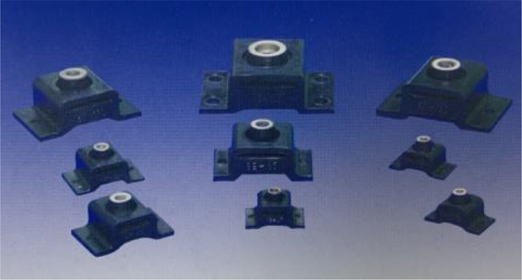
The intermediate mass of two-stage mounting system has huge impact on vibration isolation efficiency. In general, the greater the stiffness and amount of intermediate mass is, the greater the vibration isolation efficiency would be obtained. Usually, two types of intermediate mass structure are adopted, one is frame structure intermediate mass like raft, the other is distributed mass blocks. The frame structure intermediate mass is made up of plate or beam which its structural strength is weak and exists numerous medium and high vibration modal which easily leads to resonance and has adverse effect on vibration isolation efficiency. Distributed intermediate mass is made of rigid metal block with larger stiffness and small size, which is beneficial to improve vibration isolation efficiency of mounting system. 5 –8
Numerous researchers and engineers have been involved in the study of floating-rafting mounting system. The machinery floating raft were used on the main engine and auxiliary machinery of US Sea-wolf and Virginia class nuclear submarine and impressive vibration isolation effectiveness were achieved. Fromaigeat and Armange
9
introduced a raft mounting system used in the two propulsion engines and a gearbox of a French frigate, the total mass of the raft and the mounted machinery was 104 ton and 22 mounts were used to support the weight. The mounting system’s vertical natural frequency was 5.5 Hz, but the vibration isolation efficiency was not mentioned. Miura
10
discussed a two-stage mounting system for the main engine of a fisheries research vessel. The mounting system’s vertical natural frequency was 11.2 Hz and obtained a vibration acceleration level attenuation of 40dB on an average in the frequency range of 100Hz–20 kHz. Zengguang
11
designed a dynamic simulation of the equipment, raft and foundation system based on admittance principle. And numerical simulation results that in medium and high frequency range the vibration isolation efficiency mainly depend on the natural frequency of equipment and upper-stage vibration isolators
In many segments of industry, the trend has been toward more complex equipment and machines in the past few years, which are lighter and more compact than their predecessors and operate at greater speeds and power ratings. To the vibration engineer, this trend has meant more problems associated with vibration isolation problems: that is, more excitation available and more components likely to be affected adversely by them so that it has become increasingly important to provide vibration isolation systems that will retain their effectiveness. And stricter requirements on weight of mounting device and physical dimension so that can be installed under narrow cabin of naval vessel are added. Research on lightweight, miniaturization and intelligent mounting design should be carried out as soon as possible. Although floating raft mounting system has exhibited good performance on vibration isolation efficiency and radiated noise attenuation effect, their applications are becoming limited. Reasons may be various but the following factors are vital. Firstly, two-stage raft mounting system needs additional installation space and increases the weight of marine vessels. In general, the weight of a typical intermediate mass of raft mounting system usually exceeds 30% of the machinery weight which is not acceptable in many marine vessels applications as is mentioned above. Secondly, the structure design of raft has direct influence on the vibration isolation efficiency and standard designing principles are not available until today.
To solve the problems above, a novel intelligent two-stage mounting system with distributed intermediate mass is designed and researched. Two-stage mounting system having distributed intermediate mass without intelligent function was ever applied in the diesel engine of Collins class submarine and Bigelow ocean survey ship and ideal vibration isolation efficiency was achieved as presented in Table 1. 19 Two-stage mounting system having distributed intermediate mass, light in weight, taking less installation space and intelligent in function will play a more important role in the field of vibration noise controlling in the future.
Comparison of similar mounting schemes.

In this article, a novel intelligent distributed two-stage mounting system was presented. Intelligent air spring and hard elastic material were used as isolators. Air spring have widely used for vibration isolation in many fields. The simplified theoretical model of two-stage mounting system having distributed intermediate mass was analysed in the article. The equation of distributed mounting systems’ isolation efficiency expressed by velocity vibration level difference was deduced through four-pole parameters method. The influences of system designing parameters on vibration isolation efficiency were analysed. Based on analysis results and current naval machinery mounting technology, two-stage mounting system having distributed intermediate mass, comprising of air springs and hard elastic material, was established under a scale experimental prototype. Vibration isolation efficiency at different specific frequency generated by vibration exciter was tested to verify the accuracy of theoretical analysis.
Keeping alignment and stability of mounting system is the basic requirement for the marine vessels propelled by propellers which can be easily satisfied by the novel intelligent distributed mounting system designed. The controlling system monitors the real-time alignment stage when it is necessary. If misalignment occurs and exceed an alignment threshold, it controls the attitude of mounting system and eliminate misalignment by adjusting air springs’ pressure. And if misalignment has reach to a safety threshold due to a severe motion of marine vessels or failure of air spring, an emergency protection mechanism would be activated. Pushing mounted machinery equipment to the alignment and safe stage and rigidly fixing it to ensure the safety of the operating machines. Kashani 20 has ever designed a computer controlled air isolation system for a diesel generators on-board luxury watercraft. He et al. 21 introduced an air spring mounting system for marine propulsion system consisting of air spring subsystem, alignment control subsystem and safety protection subsystem which has been applied in a large-scale marine propulsion unit and obtained impressive vibration isolation efficiency and operate smoothly and safely.
The research results based on the calculation and analysis on the distributed intermediate mass mounting system with intelligent controlling system designed to equip with can be used as a reference for naval vessel noise attenuation research and engineering design if necessary.
Theoretical model of distributed mounting system
Basic theory of four-pole parameters method
Four-pole parameters method is an essentially simple idea and is helpful in providing a point of view. All of the pertinent properties of a system can be expressed in terms of four-pole parameters which characterize only the system for which they are determined; their value is not influenced by the preceding or subsequent mechanical systems.
A linear mechanical system is shown schematically in Figure 1. The system may be comprised one or more lumped or distributed elements, or be constructed from any combination of such elements. 9–10
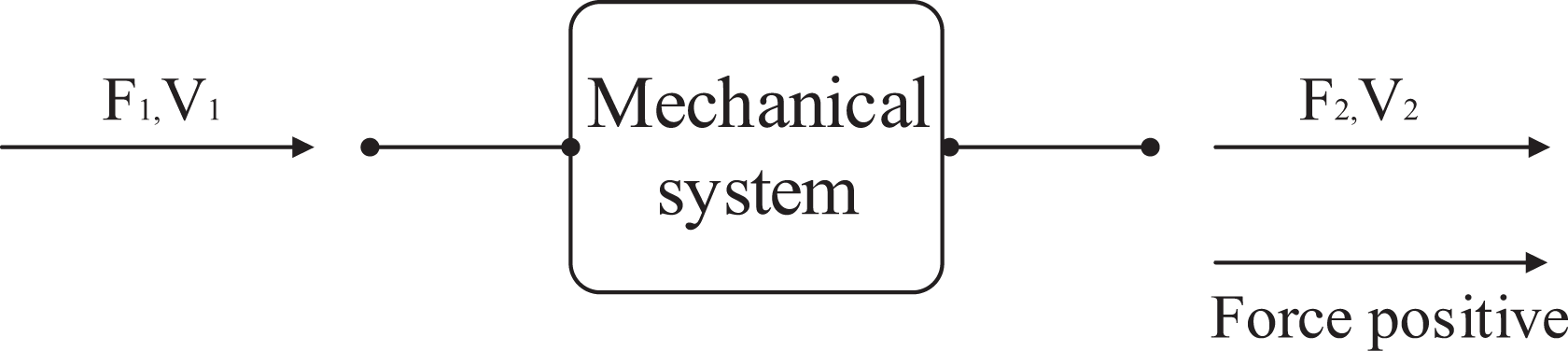
Schematic diagram of mounting system.
The vibration response of the four-terminal system of Figure 1 can be represented by the following matrix equation. The term four-pole parameters are the name applied to the four coefficients

It is directly apparent that
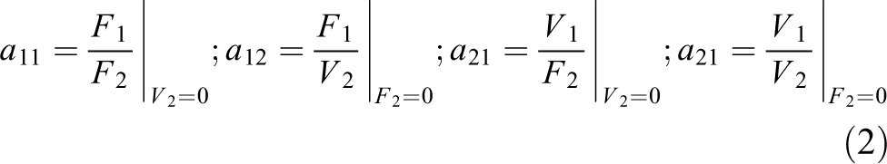
where the subscript


Theoretical model
The dynamic behaviour of mounting systems is complicated and extremely hard to predict because of wave effects. To depict the behaviour of system’s dynamic performance is difficult so that simplifying practical mounting system is necessary.
Simplified two-stage mounting system having distributed intermediate mass is shown diagrammatically in Figure 2. Here a machine of mass M vibrates with a sinusoidally varying velocity V
1 under the action of a force F
1. The machine is isolated from a non-rigid of arbitrary impedance ZF
. F
2 represents the force transiting to foundation. Here it is the purpose to demonstrate how the velocity vibration level difference of mounting system will change if intermediate mass is divided to two or more separated parts, that is M
1,M
2. Here both upper and lower mounts are modelled as damped springs. To simplify calculations, making

Simplified two-stage mounting system having distributed intermediate mass model.
It is possible to envisage the overall system as shown in Figure 3. As mentioned above, the distributed intermediate mass is considered as a rigid rectangular block in the presented model. According to the dynamics theory of rigid bodies, the relation between the input and output forces and velocities may be easily written down directly for the distributed intermediate mounting system
25–26


An equivalent four-terminal system with series-connected components.
where

In the equation above,
The receiver’s force when the mount is absent is

where ZF
represents the mechanical impedance of foundation,
Combining equations (4), (5) and (6) yields the isolation efficiency of mounting system expressed by velocity vibration level difference can be easily obtained as follows

where
Thus the dynamics analysis of two-stage mounting system having distributed intermediate mass has been conducted. The following attempt is to make further study on the design parameters on systems’ vibration isolation efficiency.
Influence of design parameters on vibration isolation efficiency
Baseline parameters used for numerical analysis
To evaluate the influence of design parameters of distributed mounting system on vibration isolation efficiency, numerical analysis is presented based on a group of baseline parameters. The upper device
Influence of stiffness of upper isolators
Figure 4 shows the receivers’ velocity curve of distributed two-stage mounting system with different k 1. It can be seen that velocity peaks are higher when stiffness of upper isolators k 1is larger. And as frequency increases, the receiver’s velocity decreases dramatically, that is to say the better vibration isolation efficiency of distributed two-stage mounting system would be obtained when the frequency increases as is shown in Figure 5. Combing Figures 4 and 5, we can safely draw the conclusion that upper isolators chosen to be adopted in distributed two-stage mounting system should qualify for low stiffness as pointed out by many authors. 27 –29

Receiver’s velocity response comparison of distributed mounting system with different k 1.

Vibration isolation efficiency comparison of distributed mounting system with different k 1.
Influence of intermediate mass
To evaluate the influence of different weight of rigid mass block on vibration isolation efficiency of distributed two-stage mounting system. The proportion of mass blocks to total mass of upper device increase from 0.1M to 0.5M, ranging from 100 kg to 500 kg. The receiver’s velocities and vibration isolation efficiency of different proportions are presented in Figures 6 and 7. It can be seen that the increasing proportion of intermediate mass to total mass of upper device leads to better isolation effectiveness. However, the gain of vibration isolation efficiency slows down when continually increase of proportion. ‘Marginal effect’ of vibration isolation effectiveness becomes obvious that is to say intermediate mass should be chosen within a proper range based on the vibration isolation efficiency index requirement especially when stricter requirement on weight of mounting device and physical dimension are becoming more and more important in mounting device designing. It is pursued by every vibration engineer to gain better isolation effectiveness at least cost of installation space and weight. From what has been discussed above, proportion of distributed intermediate mass is more recommended below 30% due to ‘marginal effect’.
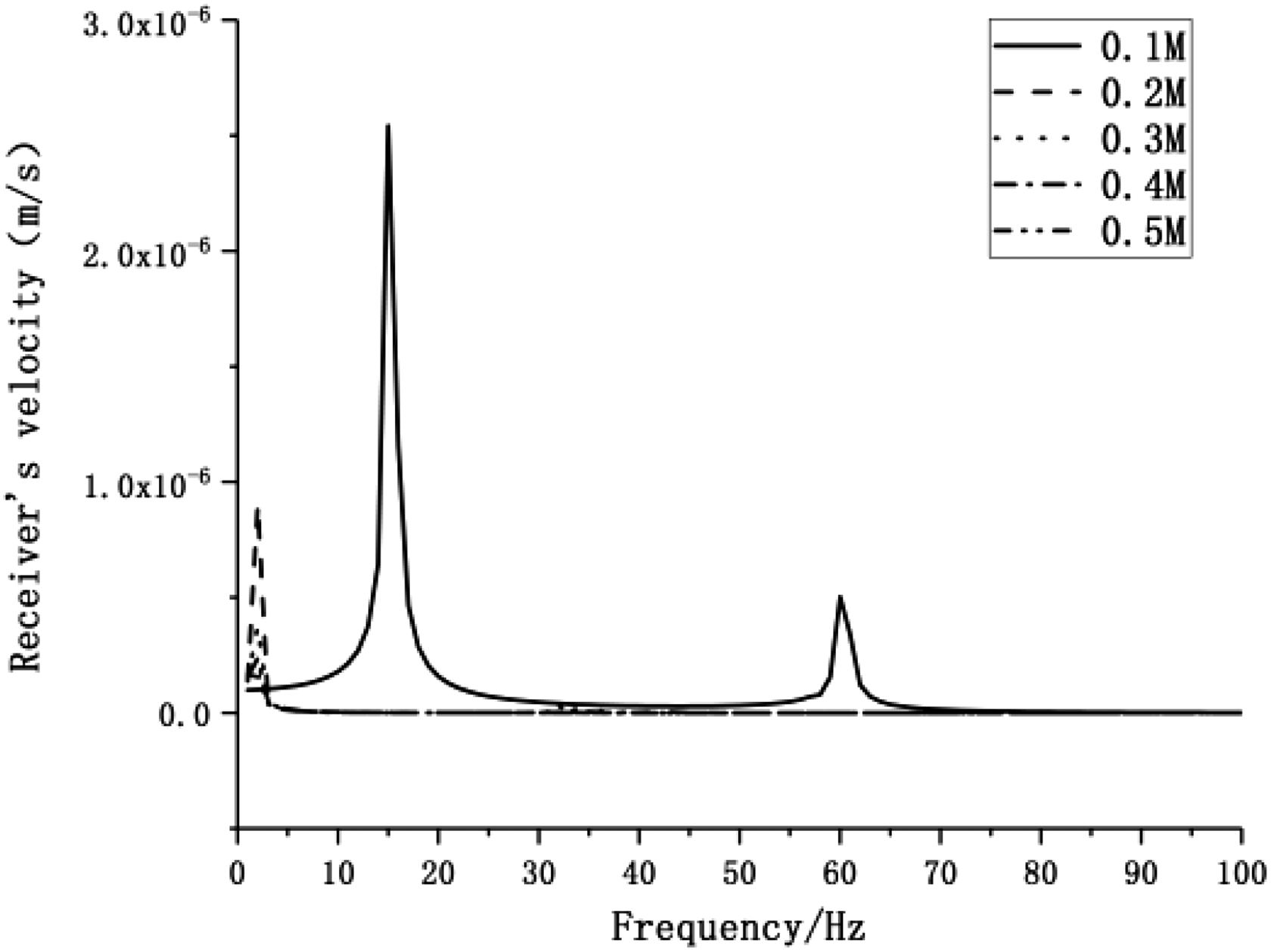
Receiver’s velocity response comparison of distributed mounting system with different M 1.

Vibration isolation efficiency comparison of distributed mounting system with different M 1.
Influence of stiffness of lower isolators
The receiver’s velocities and vibration isolation efficiency are shown in Figures 8 and 9 with the stiffness of lower isolators changing from 10e6 N/m to 10e4 N/m. It is clear that the lower stiffness of lower isolators achieves better vibration isolation efficiency. That is to say the isolator’s material should be as soft as possible. However, choice of stiffness of lower isolators should comprehensively consider vibration isolation efficiency and operating safety.

Receiver’s velocity response comparison of distributed mounting system with different k 3.

Vibration isolation efficiency comparison of distributed mounting system with different k 3.
Influence of mechanical impedance of foundation
According to relevant statistics collected, mechanical impedance of foundation usually ranges from 10e4 N·s/m to10e7 N·s/m. 30 Mechanical impedance of foundation has huge impact on vibration isolation efficiency of mounting system. Figure 10 shows the receiver’s velocities of distributed mounting system. The mechanical impedance of foundation is changing from 10e4 N·s/m to 10e6N·s/m and the vibration isolation efficiency is increased apparently as is shown in Figure 11. It can be seen that the change of mechanical impedance of foundation won’t shift the system’s natural frequencies, thus the response amplitude was influenced obviously. A conclusion can be easily obtained that optimization design of foundation to increase mechanical impedance is essential in improve isolation effectiveness of mounting system.

Receiver’s velocity response comparison of distributed mounting system with different ZF .
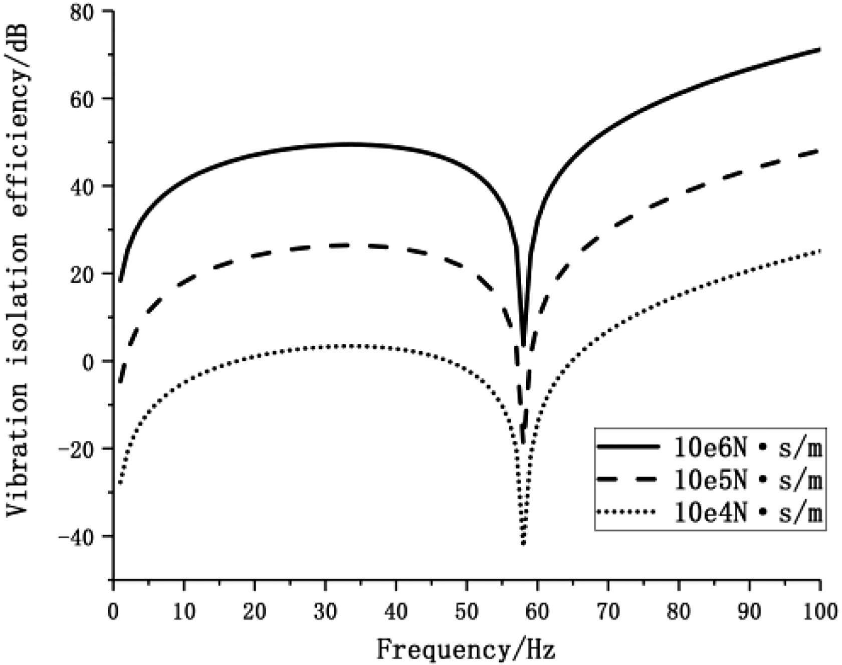
Vibration isolation efficiency comparison of distributed mounting system with different ZF .
Experiments
Establishment of experimental prototype
To validate the theoretical analysis in this article, a two-stage mounting system prototype having distributed intermediate mass was designed and manufactured. Vibration generator which generates vibration at a precise frequency is applied as vibration source as shown in Figure 12. Q235 whose density

A two-stage mounting system having distributed intermediate mass.
Isolators made of hard elastic material were used in the upper mount whose natural frequency were about 8 Hz which is mainly based on consideration of keeping the distributed mounting system’s stability in a reasonable range, being vital when used in naval vessels and its vertical stiffness is 1.5 × 10e6 N/m, damping ratio 0.09 as can be seem in Figure 13. Air spring was used in the lower mount whose natural frequency was about 4 Hz because pressured air is much softer than any other elastic material. Its initial working pressure is 0.5Mpa, stiffness is 10e6 N/m and damping ratio 0.05. The physical and sketch map of the air spring is shown in Figure 14. Weight of intermediate mass was adjustable through several separated small metal mass block amounts about 10 kg each. The proportion of distributed intermediate mass to the total mass of the upper body including a vibration generator to simulate vibration source and rack to hold it ranges from 10% to 30%, the total amount of upper device is 1500 kg. Additional mass block was designed to study vibration isolation efficiency changes with different weight of intermediate mass.
Isolators made of hard elastic material.
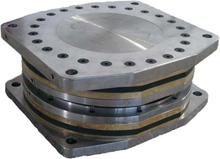
The intelligent physical map of the air spring.
Acceleration sensor placement
The isolation efficiency of the scale intelligent distributed two-stage mounting system was measured by 12 acceleration sensors. Twelve acceleration sensors were placed on the experimental prototype: four accelerations sensors were placed on the upper rack next to vibration generator which is perpendicular to the installation surface; four were arranged on upper isolations’ bottom installation surface; the rest four sensors were placed on the bottom installation surface of lower isolators. Vibration isolation efficiency refers to the difference between the vibration level tested by the uppermost sensors and the vibration level tested by the bottommost sensors.
Composition of testing system
The isolation effectiveness expressed by acceleration level difference tested by PULSE exploited by Brüel and Kjær was shown in Figure 15.

Diagram of vibration testing system.
All of the measurements summarized here were obtained after post-process using Pulse Reflex, driven by1/3 octave band filtered white noise, and by measuring1/3 octave bands. The acceleration level attenuation is
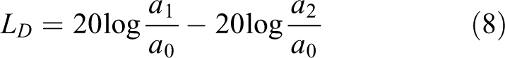
where a
1 represents the acceleration level of mounted equipment and a
2 represents the acceleration level transferring to the foundation.
Wide frequency band total acceleration level can be obtained through the equation followed

where n represents amount of 1/3 octave filters in wide frequency band.
Analysis on tested results
Influence of intermediate mass
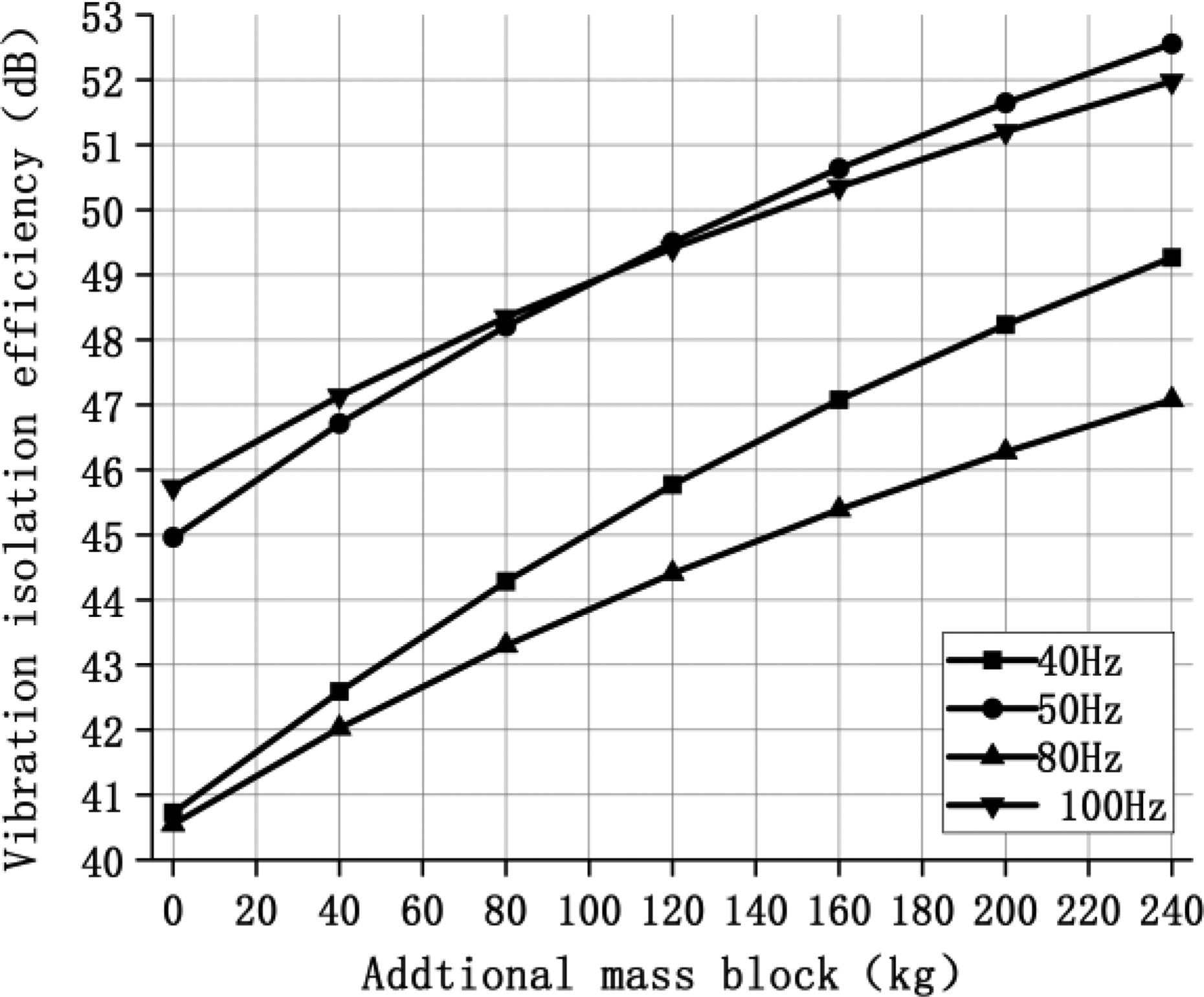
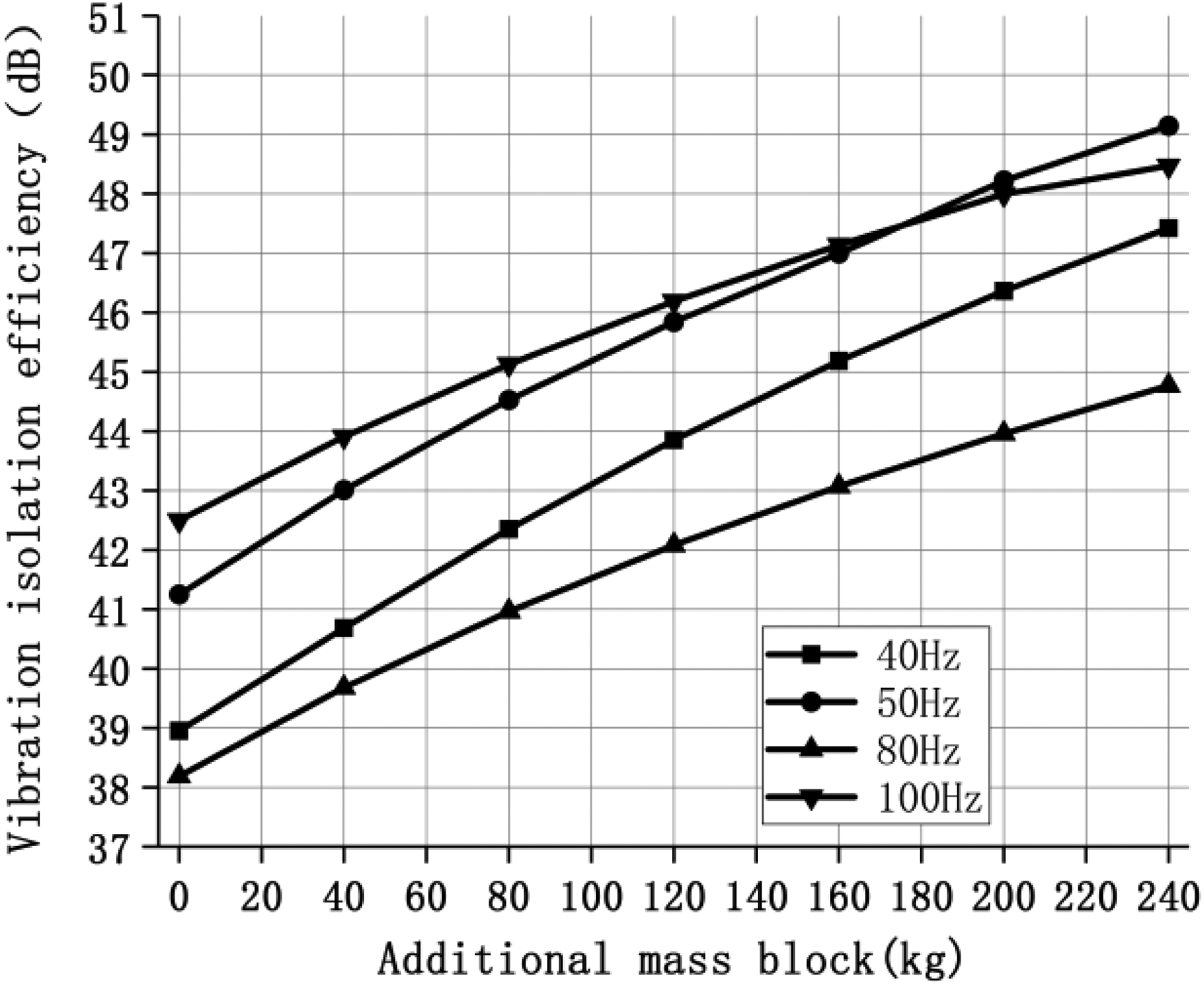
The vibration isolation efficiency expressed by acceleration level difference between vibration generator and foundation at precise excitation frequency at 40 Hz, 50 Hz, 80 Hz, 100 Hz with different additional mass blocks is shown in Figure 16, amounts of additional mass block changed from 0 kg to 240 kg. It can be seen that:
Vibration isolation efficiency comparison of distributed mounting system with different additional mass block.
The isolation effectiveness of two-stage mounting system having distributed intermediate mass exceeded 40 dB. Experimental results showed that satisfactory isolation effectiveness can be obtained by using distributed intermediate mass instead of conventional massive frame structure intermediate mass.
Greater isolation effectiveness were obtained with the increase of weight of intermediate mass and the gain of vibration isolation efficiency slows down when continually increase of additional mass blocks as predicted by theoretical analysis.
Influence of stiffness of air spring and hard elastic material isolators
Air spring is a superb vibration isolator which can be used for vibration control of power machinery in naval vessels. A new type of JYQN air spring is designed for large-scale marine machinery equipment and has been widely used in practical engineering projects. Change of air pressure will lead to change of stiffness. Vertical stiffness of air spring can be calculated by the following equation. Set the air pressure of air spring two-times as before that is to increase the stiffness of air spring.

where P represents the working pressure of air spring, Se
represents the effective area of air spring, Pa
represents the pressure of the environment, Re
represents the effective radius of effective area of air spring and
The tested results were shown in Figure 17. And change another group of hard elastic material isolators with higher stiffness, tested results after exchange of upper isolators were shown on Figure 18. It can be seen that 2–3 dB vibration isolation efficiency loss was obtained when increasing the stiffness of isolators.

Isolation efficiency of the scale experimental prototype with different k 3.
Isolation efficiency of the scale experimental prototype with different k 1.
Intelligent safety mechanism design
One of the most important problem when designing a mounting system is to ensure the operation safety of the mounted equipment if extreme condition happens. Thus safety mechanism of mounting system is designed and integrated in the distributed intelligent mounted system. Different precaution and protection methods are created to enhance the mounting system’s reliability and safety according to various types of fault and disturbance.
Intelligent distributed two-stage mounting unit
An intelligent two-stage mounting system is shown in Figure 12 which consists of upper isolators, lower isolators containing pressure sensor and solenoid valve, intermediate mass block, displacement sensor and controller. Working principle of intelligent mounting unit is shown schematically in Figure 19. The intelligent mounting system is composed of four subsystems, that is stage monitoring system, air spring system, emergency system and intelligent control system as is shown in Figure 19.

Schematic of structure and working principle of distributed intelligent mounting system.
Stage monitoring system
The stage monitoring system is to monitor the real-time placement of different points on mounted machinery equipment using displacement sensors and the real-time pressures of air spring through pressure sensors. If something goes wrong such as air leakage of air spring, air spring failure, solenoid failure, upper isolators failure and sensors failure and so on. It will be diagnosed in control software through feedback information collected by sensors. All the fault diagnosis results and maintenance advice for operators will be shown on the monitor screen so that malfunctions can be eliminated at a short time to ensure the safety of mounted machinery equipment during operation.
Air spring system
The air spring system consisting JYQN air spring is designed to support mounted machinery equipment and isolate vibration effectively. If air spring failure happens, the balance between mounted equipment and mount system will be destroyed and the mounted machinery equipment is unsafe to operate and deviate from the alignment attitude, the intelligent mounting system will activate a reconstruction mechanism, which excludes the failure air spring and reallocate the mounted equipment weight load among other normal air springs to recover the alignment attitude of equipment and maintain the isolation efficiency. Air spring system is the base of the whole intelligent control system.
Emergency protection system
The emergency subsystem is designed to rigidly fix the mounted machinery equipment through a controllable restraint when extreme condition happens such as a large-amplitude marine vessels motion or other severe faults. And after the extreme condition is cleared, the emergency protection will be disabled automatically, and restores the intelligent mounting system to elastic mounting stage. It is realized through controllable constrains which is located between intermediate mass and foundation. When it is under normal condition, there is a clearance of a couple of a couple of millimetres inside each restraint to ensure that the mounting system doesn’t contact with foundation. When emergency happens, the restraint wound be activated to eliminate the clearance inside it, making mounting system being rigidly fixed to the foundation. The schematic of emergency protection system is shown in Figure 20.
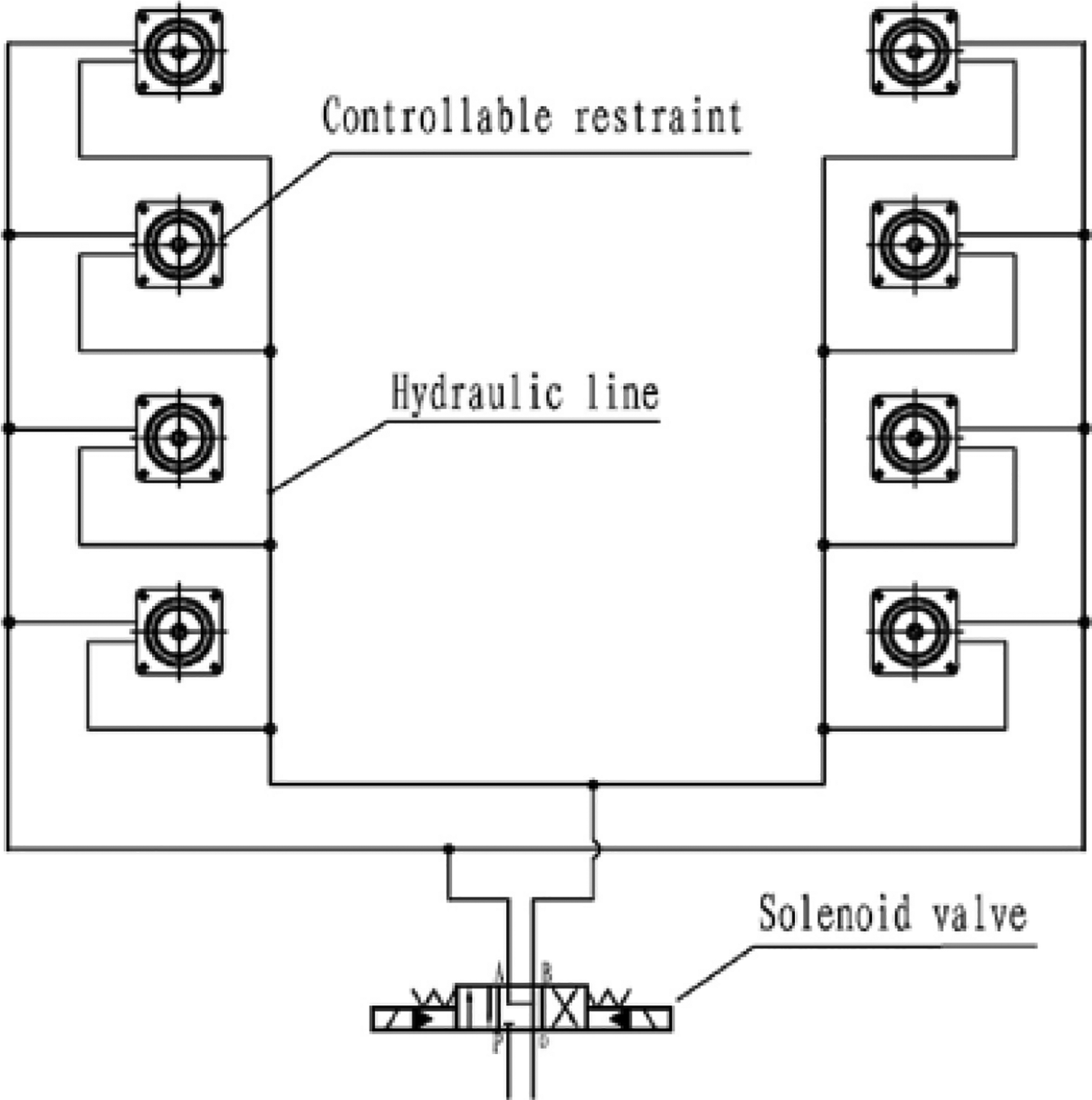
Schematic of emergency protection subsystem.
Intelligent controlling system
Intelligent controlling system which contains a controlling box and equipment to charge or deflate air springs is the head of intelligent mounting system. All sensors information feedback is proposed here. Main task of the intelligent controlling subsystem is to charge or deflate air springs and trigger the emergency protection subsystem when sensors information feedback to execute fault diagnosis and activate emergency protection system if necessary.
Conclusion
In this article, the receiver’s velocity and vibration isolation efficiency of two-stage mounting system having distributed intermediate mass were studied by four-pole parameter method. And influence of mounting system design parameters was discussed. A scale prototype of two-stage mounting system having distributed intermediate mass was designed to test the isolation effectiveness and introduction of intelligent safety mechanism design was introduced briefly. It has been pointed out:
The vibration isolation efficiency of the distributed two-stage mounting system can satisfy the practical index requirement of engineering project over 40 dB.
The theoretical and experimental results show that larger amount of rigid intermediate mass will lead to better vibration isolation efficiency if vibration isolation considered only. However, the weight of rigid intermediate mass should be chosen under a proper range based on the vibration isolation index requirement under the premise of intensity requirements of mounted equipment when applying distributed mounting system because the gain of vibration isolation efficiency slows down when continually increase of proportion. ‘Marginal effect’ of vibration isolation effectiveness becomes obvious. Proportion of distributed intermediate mass is more recommended below 30% due to ‘marginal effect’.
If vibration isolation efficiency is considered only, stiffness of isolators should be chosen as small as possible that is to say softer material of isolators should be selected. However, stability should be taken into account in stiffness configuration of mounting system considering the operational security of mounted equipment.
By properly designing the structure of the foundation to enhance the mechanical impedance is advantageous in improving vibration isolation efficiency.
The usual frame designs, however, incorporate extended structural members which exhibit modal behaviour at acoustic frequency; thus, such frames do not act as rigid masses at these frequencies and the advantages of a two-stage mounting system are lost. In many such installations it is likely that better high-frequency isolation, plus perhaps a saving in weight, may be obtained essentially by replacing the frame with distributed compact mass which will act as rigid mass at high frequency like the two-stage mounting system having distributed intermediate mass I discussed in the article.
The novel two-stage system combined with the advantage of compact size, lightweight, automatic in function and overturning torque cancellation functions has been proved as a new mounting scheme which will be used in a large scale machinery equipment in near future.
Further research on detailed physical explanation about why would distributed intermediate mass provide better vibration isolation efficiency and experiments on large scale mounted equipment will be continued.
Footnotes
Declaration of Conflicting Interests
The author(s) declared no potential conflicts of interest with respect to the research, authorship, and/or publication of this article.
Funding
The author(s) received no financial support for the research, authorship, and/or publication of this article.