
Abstract
To satisfy the needs of surgeons for judging the contact state of the catheter robot and modify the operation accordingly, a novel contact torque estimation and haptic feedback method is proposed in this article. Using the vibrotactile feedback, the proposed method reminds the surgeon which bending unit of the robot contacts with human tissue and guides him to realize the disengagement. Based on a novel simplification of the driving force of the robot, a quasi-statics model is established to estimate the contact torque. Simulations are conducted based on Finite Element Method (FEM) to verify the accuracy of the quasi-statics model and the estimation method. A robot system composed of a catheter robot, a PC, a master-operator, and a wearable vibration glove is assembled according to this method. To verify the feasibility of this method, a contact torque estimation experiment and a vibrotactile feedback experiment are conducted in this article. The results show that this method is accurate and effective.
Introduction
In the traditional interventional surgery, the surgeon relies on the hand feeling to control the movement, detect the contact between the catheter robot and the natural lumen of human body, and avoid obstacle by experience. However, this dependence will increase the probability of misoperation and bring a high safety risk. Therefore, how to accurately detect the contact between catheter and tissue and feed it back has become a key issue to improve the safety of minimally invasive surgery (MIS).
At present, researchers mainly use force sensors to measure the contact force at the end of the robot in a robot-assisted surgery. McKinley et al. designed a tactile sensor based on displacement detection for the recognition of subcutaneous vessels in MIS. 1 –3 Li et al. designed a triaxial force sensor based on strain gauge, which can measure forces in the three directions of X, Y, and Z axes. 4 However, the sizes of the sensors are larger than 10 mm. As the diameter of the catheter robot is smaller than 8 mm, very few sensors can be installed on the end of the robot. These sensors can only detect the contact force at the end rather than the whole body of the robot. In addition to the sensor measurement method, the contact force can be estimated according to the quasi-static model of the robot. The sensor-less estimation method of contact force and torque has become a research hotspot in the field. Hasanzadeh and Sharifi 5 established the quasi-static model for intracardiac catheters and, based on this model, estimated the contact force at the catheter tip according to the catheter posture obtained through Computerized Tomography (CT) image. Soltani et al. 6 proposed a shape-based three-axial force and stiffness estimator based on the Cosserat rod model for tendon-driven catheters. Back et al. 7 proposed a multielement kinetostatic model of a tendon-driven catheter and calculated the actual contact force according to the shape of the catheter and the location of the contact obtained from image processing. The shape of the catheter is obtained through the CT images in the above methods. However, due to the lack of depth of field, the CT image cannot accurately represent the position and posture of the catheter.
To solve this problem, the kinematics model is introduced to estimate the shape of the robot. Haraguchi et al. 8 designed a flexible surgical operator driven by cables pulled by pneumatic cylinders and established its kinematics and dynamics model to determine the relation between the end contact force and the pulling force of the driving cables. The end contact force can be estimated according to the pulling force of driving cables. Roy et al. 9 proposed a simplified dynamics model of a single-segment continuum robot to replace the traditional statics model and estimate the end contact force and torque according to the driving force. Black et al. 10 designed a parallel continuum robots and provided a generalized Cosserat-rod-based kinetostatic model framework to estimate the shape and calculate the contact force.
However, most of the existing estimation methods are to estimate the contact force at the end segment of the multi-segment robot and lack the estimation of the contact force or torque of other bending segments. Without sensors, it is difficult to estimate the contact force or torque of nonterminal bending segments. The difficulty lies in the coupling state between the position and the magnitude of the contact force. According to the mathematical model, only the resultant torque rather than the exact contact force can be obtained. However, the resultant torque can still play an important role in MIS. It can be fed back to prompt the surgeon that a certain bending unit contacts with human tissue. Then, the haptic feedback guides surgeon to adjust the joint vector of the bending unit, to gradually reduce the resultant torque and make it disengage from the human tissue.
The measured contact forces need to be accurately fed back to guide surgeons to avoid obstacle. This requirement can usually be met by haptic feedback. 11 –16 However, the feedback force will affect the operation of the surgeon In order to avoid the negative effect improve the stability in teleoperation, a method named sensory substitution was presented. 17 Avoiding the usage of force feedback device, this method substitutes force feedback with stimuli of another sensory modality. 18,19 A fingertip cutaneous device was designed by Pacchierotti to provide the cutaneous feedback instead of the force feedback. 20 Based on the sensory substitution, Prattichizzo et al. presented a sensory subtraction method, in which the kinesthetic feedback is removed. 21 It is shown that cutaneous feedback provided by a moving platform is more effective than sensory substitution via visual feedback. In the field of MIS, Meli et al. designed a novel cutaneous device based on sensory subtraction to force feedback in robot-assisted surgery. 22 However, in the feedback of multidimensional torque, the cutaneous feedback in above methods is not competent as the Degree of Freedom (DOF) of the device is limited. Therefore, a vibrotactile feedback method is proposed in this article to feed back the estimated contact torque.
A sensor-less contact torque estimation and haptic feedback method is proposed in this article. The contact torque of each bending unit is estimated according to the output torque and motion of motors based on the quasi-statics model of the catheter robot established in this article and substituted by the vibration to feedback to surgeon by a wearable haptic device.
Methodologies
The principle of the estimation and haptic feedback method is shown in Figure 1.

Principle of the method.
The catheter robot is a master-slave system. In master-side, the surgeon wears a vibrotactile feedback device and determines the target position of the catheter robot through the master-operator. In the process of moving, the torque estimation module calculates the contact torque of each bending unit based on the kinematics and quasi-statics model of the catheter robot. When a certain bending unit contacts with human tissue, the driving force changes instantaneously. Based on the model, the contact torque can be estimated through the change, and then, the torque can be converted into vibration and feedback to the surgeon. Guided by the feedback, the surgeon moves the master-operator to change the joint variable to reduce the torque. When the operator feels the vibration stimulus disappear, the catheter robot can be considered to be out of contact with the tissue. When multiple bending units of the catheter all come into contact, the contact torque can be feedback unit by unit to guide the surgeon to adjust the joint variables of each unit so as to realize the disengagement of the catheter robot from the human tissue.
Principle of the estimation approach
The principle of the torque estimation module is shown in Figure 2. The motion controller of the catheter robot gets target position from the master-operator, converts the position into joint variables and motor parameters based on inverse kinematics model, and controls the actuation unit (motors). The motion of the actuation unit can be converted into the posture of catheter robot based on the direct kinematics model. The contact torque can be estimated by the position and posture of the catheter robot and output torque of the actuation unit.

The principle of the torque estimation module.
For the convenience of modeling and analysis, four assumptions are applied in this article.
Assumption 1
The centerline of the backbone and the driving cables bend in a circular shape, and the length of centerline does not change during bending. The circular shape is realized by the Nitinol (NiTi) alloy material of backbone and guiding disks.
Assumption 2
The catheter robot can be modeled by quasi-statics model as its velocity is very slow (lower than 5 mm/s).
Assumption 3
After contact with human tissue, the bending unit maintains a fixed circular shape.
Assumption 4
The quasi-statics model conforms the large deflection theory.
The nomenclature used in this article is given in Table 1.
The nomenclature used in this article.

Kinematics model
The catheter robot is composed of N bending units. The structure of the bending unit is shown in Figure 3. The bending unit is composed of a flexible backbone (NiTi), several guiding disks, and three driving cables. The driving cables are distributed along the circumference and fixed on the end disk. By changing the length of driving cables, the bending unit can be driven to achieve bending and torsion motion.
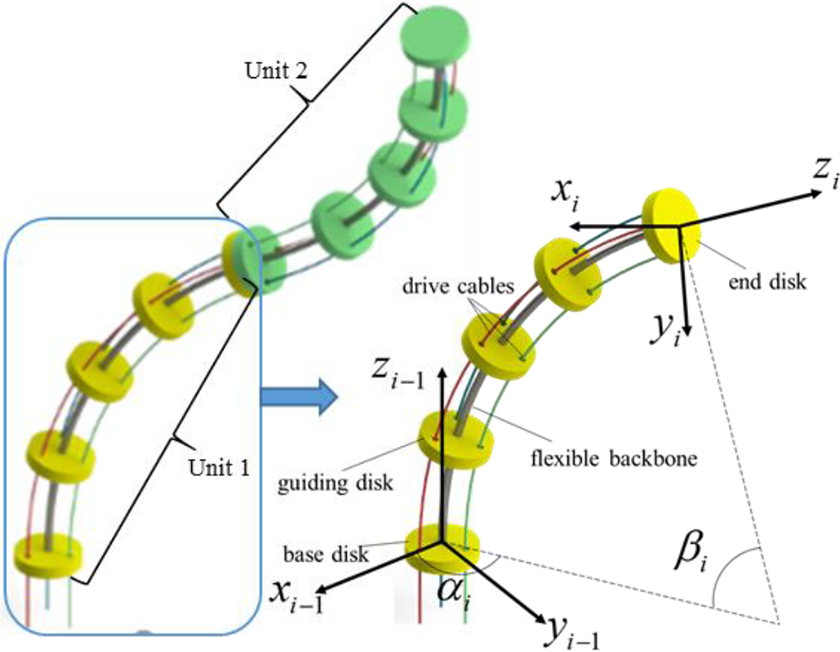
The structure of the bending unit.
In order to determine the relative motion relation between adjacent units of the catheter robot, a coordinate system is fixed at the end disk of each unit as shown in Figure 3. The coordinate system fixed with the base disk of the ith unit is denoted as {i − 1}, which coincides with the coordinate system fixed with the end disk of the i − 1th unit. The coordinate system fixed with the end disk of the ith unit is denoted as {i}. In the ith unit, the origin oi − 1 of {i − 1} coincides with the center of the base disk. Z-axis zi − 1 is parallel to the tangent line at the starting point of the centerline, pointing to the next unit. X-axis xi − 1 is on the base disk, pointing to the center of the guide hole of the first cable. Y-axis yi − 1 is determined by the right hand rule, namely, yi − 1 = zi − 1 × xi − 1.
The transformation of coordinate system {i} to {i − 1} is shown in equation (1)

The transformation of the end coordinate system {n} to the base coordinate system of the catheter robot composed of n bending units is shown in equation (2)

The mapping relation between the joint space and the working space of the catheter robot can be obtained by (1) and (2). According to this mapping relation, the overall shape and posture of the catheter robot can be calculated according to the joint variables of each unit. This is a prerequisite for estimating the contact torque of the catheter robot.
The mapping relation between the driving space and the joint space is shown in equations (3) and (4)


According to this mapping relation, the joint variables of the catheter robot can be calculated; according to the output motion of the actuation unit, the overall shape and posture can be obtained finally.
Quasi-statics model
Simplification of the driving force
As a prerequisite for modeling, a simplification of the driving force is established based on the research of Camarillo et al. 23 and Prasai et al. 24 The analysis of the contact force between cable and the bending unit is shown in Figure 4. The structure of the guiding holes can be equivalent to a guiding channel. Take cable 1 of a unit composed of 20 guiding disks as an example; its pull force FT applies on the end disk and the distributed pressure ws applies on the cable channel.

Analysis of the contact force between cable and the bending unit.
The simplification is analyzed on a plane e which formed by the curved arc of the cable and its center. A plane coordinate system is established. The origin point is the center of the guiding hole, which is also the point of intersection between the driving cable and the base plane of the unit. X-axis ex points to the center of the curved arc and y-axis ey is perpendicular to ex.
Let the value of the driving force be T, then the distributed pressure ws is shown in equation (5)

where κ c is the curvature of the curved arc of the cable, as shown in equation (6)
Fp is the force at a point along the curved arc of the cable at angle, as shown in equation (7)

Thus, the representation of ws in the coordinate system exy is obtained in equation (8)

The distributed force ws can be equivalent to the force Fs acting on the middle point of the curve and pointing to the center of the curve, as shown in equation (9)

The driving force and torque of the cable are shown in equations (10) and (11), respectively
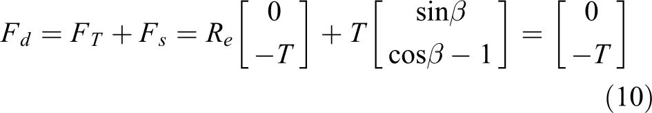

Therefore, the forces applied by the cable on the unit can be equivalent to the vertical downward pulling force on the center of the guiding hole on the base disk of the unit.
Quasi-statics model
The overall forces applied on the ith bending unit include the load [Fli, Nli ] T , cable driving force Fdi , contact force Fci , and supporting force of the i − 1th bending unit [Ffi , Nfi ] T . The load, acting on the end disk, is the reaction force of the supporting force applied by the ith unit to the i + 1th unit. The contact force acts on the body of the ith unit and the contact position is unknown. The driving force is equivalent to a force system composed of three forces acting on the center of the guide hole of the base disk, respectively. The supporting force also acts on the base disk.
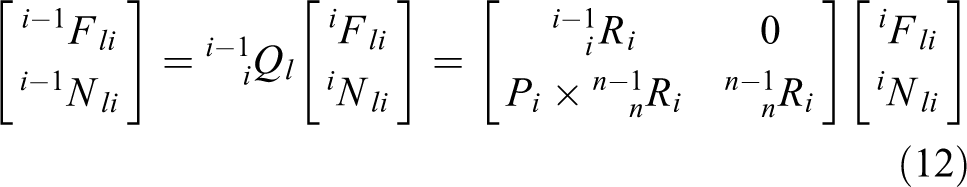
The quasi-statics model is adopted to analyze the forces of the bending unit because of the slow moving velocity of the catheter robot. In order to facilitate the analysis, the equivalent simplification of each force toward the origin of the coordinate system {i − 1} is carried out in this article. The equivalent force of the load is shown in equation (12)
Similarly, the equivalent force of contact force is shown in equation (13)

The driving force is shown in equations (14) and (15)


The force balance equation is shown in equation (16). Based on equation (16), the load of the bending unit can be recursed unit by unit

According to the large deflection theory, the relation between the joint variables of the bending unit and the driving force and load and contact force is shown in equation (17)

When the ith unit contacts with the human tissue, the value of driving force will jump to remain the same joint variables. The relation between the forces applied on the bending unit before and after contact is shown in equation (18)

The change value of the equivalent driving torque is equal to the contact torque, as shown in equation (19). The change value can be calculated according to the output torque of the driving motors

Since P c, the acting position of the contact force, is unknown, it is impossible to calculate the value of Fci according to equation (19). As i − 1 Nci is a function of Fci , and the value of the contact force is related to the position and posture of the bending unit. When the value of i − 1 Nci is changed to 0 by the operation of surgeons, the value of Fci can be determined to be 0. At this position and posture, the unit disengages from human tissue.
For a single bending unit, the contact torque can be estimated by the changed value of the driving forces according to equation (19) as its load remain unchanged. However, for an n-unit robot, if its ith unit contacts with tissue, the driving forces and load of the first unit to the ith unit will all change. Based on equations (16) to (19), the forces applied to each bending unit can be calculated from the nth unit to the first unit. Then, the unit contacted with tissue can be found out and the contact torque can be estimated.
Vibrotactile feedback method
When the catheter robot contacts with the human tissue, the direction of feedback torque may be inconsistent with the direction of movement of the master-operator. In this condition, the torque would force surgeons to move in the wrong direction. To solve this problem, a vibrotactile feedback method is introduced in this article. Based on sensory substitution, this method converts the value and direction of torque into vibration intensity and position and feeds back the vibration to surgeons by a wearable vibrotactile system. 25 The mapping relation between the torque and vibration intensity is shown in equation (20)

where fx , fy , and fz are the vibration frequency, k is a factor, and Mx , My , and Mz are the torque vector on the x, y, and z axes. The mapping relation between the direction of torque and vibration positions is shown in Figure 5. According to the grasp shape of the glove, motors fixed on index finger tip (represents −x), center of the palm (represents +x), thumb root (represents −y), little finger root (represents +y), middle finger root (represents +z), and thenar eminence (represents −z) are chosen to be controlled. Connect lines of the three sets of motors are approximately orthogonal to each other and parallel to each coordinate axis of the base coordinate system in the workspace of the master-operator. According to the actual direction of the torque, vibration motors at different positions are activated, respectively.
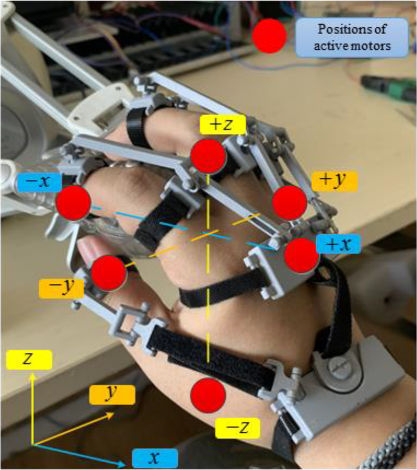
Positions of active motors.
Simulation
Simulation of the large deflection theory
The quasi-statics model is based on the large deflection theory. In order to verify whether the bending unit of the catheter robot conforms to the large deflection theory, a simulation is conducted according to the finite element method. The physical parameters of the unit are given in Table 2.
Physical parameters of the unit.

The setting of FEM software is shown in Figure 6. The base disk of the model is fixed, while three driving forces are applied to the cables. By changing the driving forces, the bending angle and twisting angle can be changed.

The FEM setting of simulations A and B.
Simulation A
When twisting angle α = 0°, verify the relation between the bending angle β and the driving force. First, as a reference, the driving force is calculated according to the different bending angle based on the large deflection theory, and then get the relation between the driving force and the bending angle in FEM software. Finally, two force-angle curves are compared and errors are calculated. The result is shown in Figure 7(a). The maximum error between the simulation value and the reference value is 2.0%.
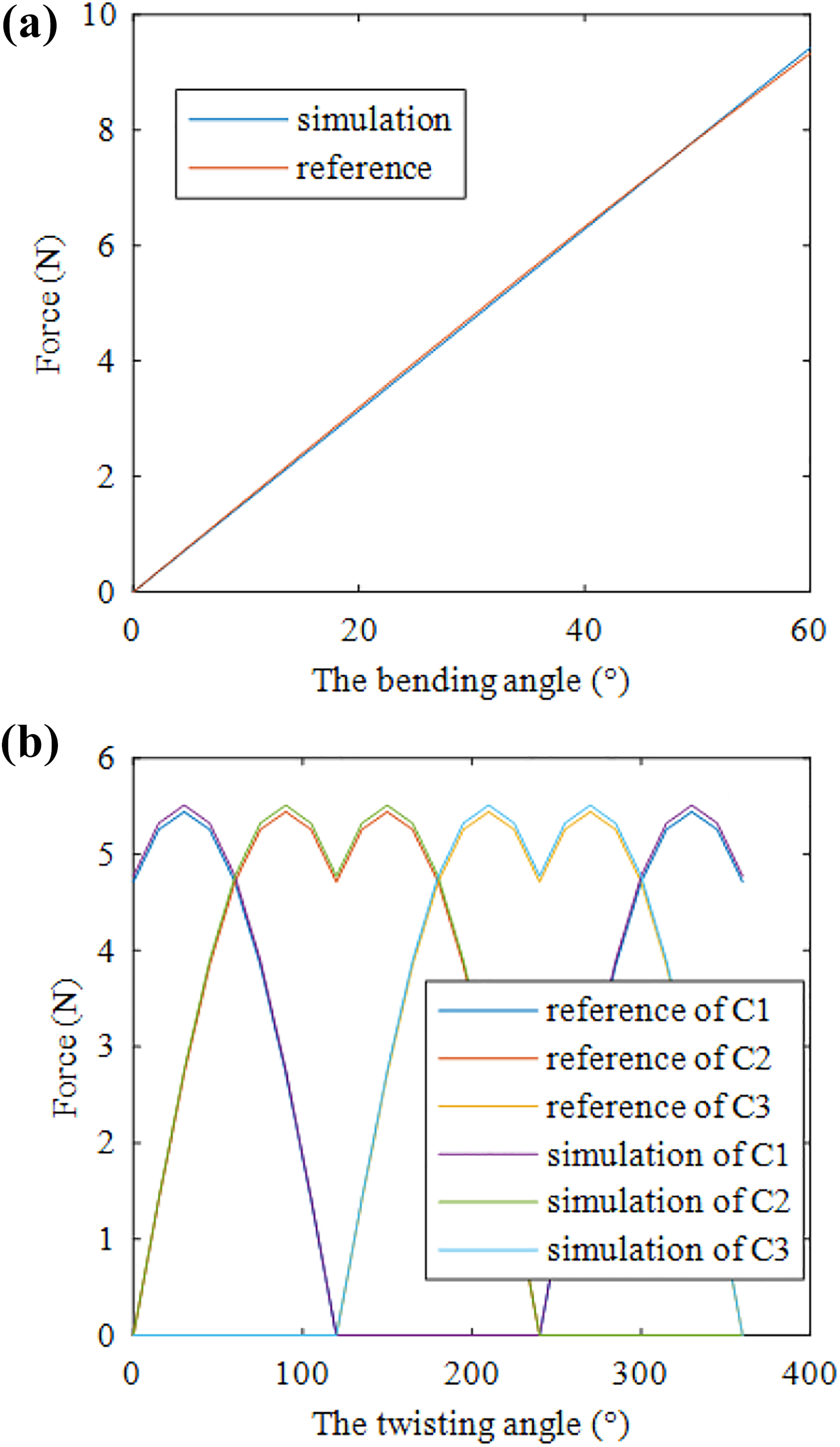
Simulation of large deflection theory: relation between (a) driving force and bending angle and (b) driving force and twisting angle.
Simulation B
When bending angle β = 30°, verify the relation between the twisting angle α and the driving force. The steps are similar to simulation A. The result is shown in Figure 7(b). The maximum error between the simulation value and the reference value of the driving force on each cable is 1.26%.
The result shows that the model of the bending unit conforms to the large deflection theory.
Simulation of the contact torque estimation method
In order to verify the accuracy of the estimation method proposed in this article, simulations of the contact torque estimation for a single bending unit and a three-unit catheter robot are conducted, respectively.
The setting of FEM software is shown in Figure 8. Different with the setting of simulations A and B, load force, load torque, and contact torque are applied to the model additionally. For the three-unit robot, the simulations are carried out unit by unit. The forces applied on each unit are calculated according to the quasi-statics model. The material of the cables is Niti. The material parameter of the cables is similar with the Niti backbone. The cables are fixed on the end disk. The contact type between cables and disk is chosen as bonded.
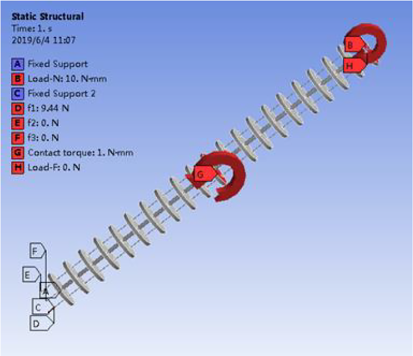
The FEM setting of simulations C and D.
The method of obtaining simulation value in finite element software is as follows. First, apply the driving forces, load on the FEM model to make it bending, and obtain the force-deflection curve. Second, apply five contact torques on the model at different joint variables as reference and obtain the changed driving forces. Then, estimate the contact torques by the changed driving forces according to the estimation method and compare the estimated torque with the reference torque. The contact parameters are given in Table 3.
Simulation parameters.

Simulation C
Purpose of the simulation is to verify the accuracy of the estimation method for a single bending unit. The estimated contact torque is determined by the driving forces according to the estimation method. The driving forces are obtained in FEM software. The result is shown in Figure 9. As shown in Figure 9(a), the driving force changes when the unit contacts with human tissue. The estimated contact torque is compared with the reference torque in Figure 9(b). The maximum error between the reference and simulation torque is 4.27%.
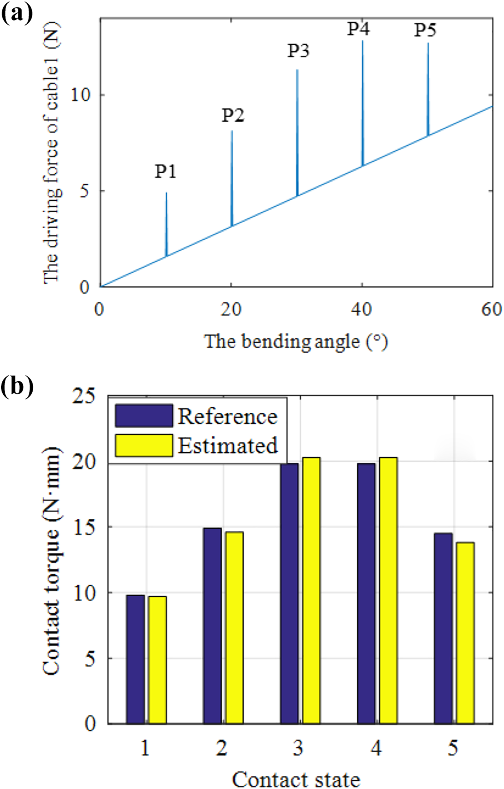
Results of simulation C: (a) the driving force of the single unit with and without contact and (b) contrast between the reference and estimated contact torques.
Simulation D
Purpose of the simulation is to verify the ability of the estimation method to detect which unit contact with the human tissue and estimate the contact torque. Depending on the contact unit, this simulation divides into three phases such as D1 (the third unit contacts), D2 (the second unit contacts), and D3 (the first unit contacts). In phase D1, the third unit bends from 0° to 60° while both the second and first units remain at 30°. In phase D2, the second unit bends from 0° to 60° while both the third and first units remain at 30°. In phase D3, the first unit bends from 0° to 60° while both the third and second units remain at 30°. The process of each phase is similar with simulation C. The results are shown in Figure 10. A phenomenon is shown in Figure 10(a) to (c). It is that when the third unit contacts with human tissue, the driving forces of the third, second, and first units are all changed. When the second unit contacts with human tissue, the driving forces of the second and first are changed while the driving force of the third unit remains the same. When the first unit contacts with human tissue, only the driving force of the first unit is changed. This phenomenon can be summarized as follows. For an n-unit catheter robot, the driving forces of the first to the ith unit will be changed and the driving forces of the i + 1th to the nth unit will remain the same when the ith unit is in contact. According to this phenomenon, this estimation method can determine which unit is in contact. A comparison between the simulation and the reference torque is shown is Figure 10(d). The maximum error of the first, second, and third units is 6.71%, 5.32%, and 4.76%. The result shows that the estimation method is accurate and effective.

Results of simulation C: (a) the driving force of the third unit; (b) the driving force of the second unit; (c) the driving force of the first unit; and (d) contrast between the reference and estimated torque in simulation D.
Experiments
In order to verify the effectiveness of the proposed contact torque estimation and haptic feedback method, an estimation experiment and a vibrotactile feedback experiment are carried out in this article. The catheter robot system is shown in Figure 11.
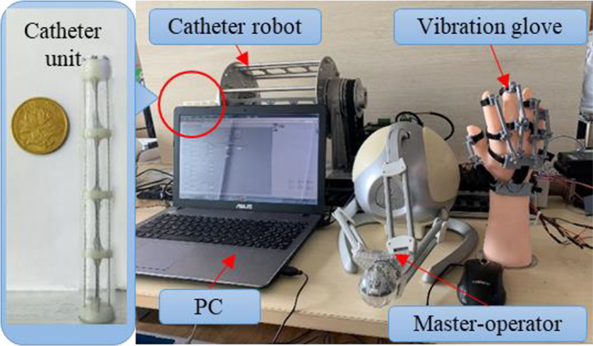
The catheter robot system.
It is composed of a catheter robot, a PC, a master-operator, and a wearable vibration glove. The experimenter wears the vibration glove to control the movement of the master-operator. The movement of the master-operator is transformed into the target position of the catheter robot to realize obstacle avoidance and other actions.
Estimation experiment
The setting is shown in Figure 12. This experiment is divided into three phases. The setting of each phase is given in Table 4. In each phase, a contact torque increasing from 0 N·mm to 60 N·mm is applied by the force sensor as a reference torque. According to the motor output torque and the position and posture of the catheter unit, the contact torque is estimated and compared with the reference torque.

The estimation experiment.
Setting of each phase.
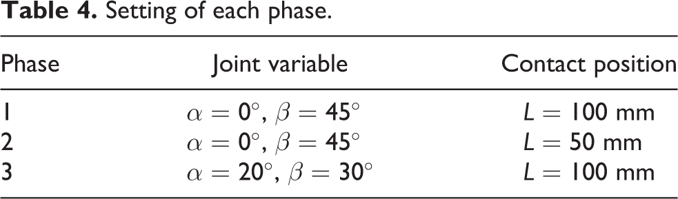
The experimental result is shown in Figure 13. The maximum errors of phase 1, phase 2, and phase 3 are 4.81%, 4.66%, and 4.78%. This result verifies the accuracy and effectiveness of this method. Comparing the curves of phase 1 and phase 2, it can be drawn that the contact position has no effect on the estimation method. The values of the joint variables also have no effect on the estimation method according to the comparison between the curves of phases 1 and 3.

The result of the estimation experiment.
Vibrotactile feedback experiment
This experiment is conducted on 24 subjects (12 females and 12 males), aged between 21 and 35. Each subject needs to wear a soundproof headset and listen to the white noise to avoid the influence of noise. In the experiment, the subject moves the master-operator to control the catheter robot disengage from human tissue according to different feedback methods in virtual environment. The time and maximum contact torque of the operation is recorded and compared to determine the optimal feedback method.
This experiment is divided into two stages, namely, the stage of torque feedback and the stage of vibrotactile feedback. In stage 1, the subject does not wear vibration glove, receives the torque feedback through the master-operator, and controls the movement of the catheter. When the subject cannot feel the torque feedback subjectively, it can be considered that the disengagement operation is completed, and the subject should press the end button. At this time, the system records the completion time and the maximum contact torque.
In stage 2, the subject wears a vibration glove and the master-operator does not provide the torque feedback. Similar to stage 1, when the subject cannot feel the vibration, press the end button and the system records the completion time and the maximum contact torque. In order to avoid the teaching effect, subject needs to rest at least 1 h between two stages. Experimental parameters are given in Table 5.
Experimental parameters.

The result is shown in Figure 14. The average operating time of the torque feedback is 75.58 s and the standard deviation is 26.36 s, while the average operation time of the vibrotactile feedback is 41.54 s and the standard deviation is 19.57 s. The average maximum torque of the torque feedback is 112.62 N·mm and the standard deviation is 20.42 N·mm, while the average maximum torque of the vibrotactile feedback is 86.14 N·mm and the standard deviation is 5.01 N·mm. The reason is that in the process of operation, the direction of contact torque is not always consistent with the direction of the motion that should be realized by the master-operator. In this case, the control of the master-operator by the subject is affected by the feedback torque, which reduces the stability and safety and increases the operation time. This experiment proves that it is feasible to use the vibrotactile feedback the contact torque and guide the surgeon to realize the disengagement of the catheter robot.

The result of the vibrotactile feedback experiment: (a) operation time of different feedback method and (b) maximum contact torque of different feedback method.
Conclusion and discussion
In this article, a contact torque estimation and haptic feedback method is proposed to satisfy the needs of surgeons to judge the contact state of the catheter robot and modify the operation accordingly. In this method, the surgeon wears a wearable vibrotactile device, gets the vibrotactile feedback as a haptic feedback, and controls the movement of the catheter robot through the master-operator according to the feedback. The vibrotactile feedback is used to feed back the estimated contact torque.
This method consists of contact torque estimation and haptic feedback. The estimation approach is based on the kinematics model and quasi-statics model. The contact torque can be estimated by the output of driving motors according to this approach. To verify the accuracy of the estimation approach, simulations and experiments are conducted. The maximum simulation error of the single unit is 4.27% while the maximum simulation error of a three-unit robot is 6.71%. The results of simulation show that if the contact unit get to the base closer, the error is bigger. The reason is that the driving forces of the close unit are larger than the far unit. The changed value of the driving forces is not obvious.
The experiment, divided into three phases, is conducted on a single unit. The maximum errors of each phase are 4.81%, 4.66%, and 4.78%. The results of the experiment show that the estimation method is accurate and effective. However, the maximum error of the experiment is larger than the simulation error of the single unit. The larger estimation error in experiments is caused by the modeling errors and friction between the driven cables and the robot. The next step is to improve the modeling method to reduce the modeling errors and compensate the friction.
According to this estimation method, the contact torque of each bending unit of the catheter robot can be estimated. The contact torque of the end-unit can be used as force feedback to modify the position of the end of the robot to ensure that the contact force is consistent with the reference value in force control or force-position control. However, due to unavailable contact position of other bending unit, it is hard to establish the mapping relationship between joint variables and contact force. Therefore, the force control and force-position control are not applicable to compensate the contact force of the body of the robot. To solve this problem, the surgeon is added in the control loop. According to the feedback contact torque, the surgeon can only reduce the contact torque by trying to change the joint variables.
The haptic feedback approach is converting the contact torque to the vibrotactile stimuli by a wearable vibrotactile device. This approach solves the problem that the torque feedback may force surgeons to move in the wrong direction. To verify the feasibility of this method, a vibrotactile feedback experiment is conducted. The results show that the problem exists and the vibrotactile feedback is effective.
The results of simulations and experiments show that this contact torque estimation and haptic feedback method is feasible and effective. However, the unavailable mapping relationship between the contact force and joint variables caused by the unknown contact position increases the time of trial and error and reduces the operating efficiency. To solve this problem, the next research will focus on the method to determine the contact position without sensors.
Footnotes
Declaration of conflicting interests
The author(s) declared no potential conflicts of interest with respect to the research, authorship, and/or publication of this article.
Funding
The author(s) disclosed receipt of the financial support for the research, authorship, and/or publication of this article: This work was supported by the National Natural Science Foundation of China (no. 51575256), Natural Science Foundation of Jiangsu Province under grant BK20170789 and BK20191272, and the Fundamental Research Funds for the Central Universities (no. NS2018033).