
Abstract
In fiber voltage sensor, imperfect fiber splicing angle and length difference between the sensing fiber and the compensating fiber usually influence the system output performance. This article established the mathematical model of the system output error using the Jones matrix and analyzed the relationship between the system output error and the above two error factors, respectively. The results show that the angle error of 90° splice has a significant influence on the system output, and the tolerance of angle error varies with different test voltages. When the test voltage is higher than 6 kV, if the expected system error is less than 0.02%, the splicing angle error should be less than 0.15°. Additionally, the length difference also has a significant influence on the system output accuracy. The length difference between sensing fiber and compensating fiber should be less than 1 µm when the test voltage is 110 kV so that the system can meet the accuracy requirements of IEC 0.2s. This research provides a reference for the development of fiber voltage sensor based on the converse piezoelectric effect and also provides a basis for the design of intelligent power detection robot system.
Introduction
Optical fiber sensing has been applied in robot field due to its advantages of long detection distance, short response time, and high resolution. 1 With the development of smart grid, intelligent inspection robot is widely used in power system in order to obtain information of power equipment accurately and safely. 2 –4 However, the voltage is one of the power systems. In order to obtain standardized and electrically isolated voltage signals and ensure the safe operation of the power system, it is necessary to use voltage sensors to collect the voltage signal. Compared with traditional voltage sensor, optical voltage sensor (OVS) has a series of advantages, such as a relative simple setup, intrinsic safety, excellent scale factor, small size, low weight, and, with closed-loop detection, a linear response over an extended dynamic range. 5 –8 Up to date, the two kinds OVS, which the Pockels effect and the converse piezoelectric effect, popular with most researchers. 9 The OVS based on the Pockels effect is more mature and has trial operation equipment. However, fluctuations in light intensity affect the accuracy of the measurement. The linear response range depends on the half-wave voltage of the Pockels crystal, which limits dynamic range and sensitivity. 10 Compared with it, there is no discrete optical component in the converse piezoelectric effect OVS, such as slides, analyzers, and bulk crystal, which avoid interfering of other electro-optic effects on the optical path and simplify the structure and manufacturing process. 11 Meantime, reflective reciprocity structure is also highly appreciated by many researchers in the research of OVSs and optical current sensors. 12 –14 However, the converse piezoelectric all-fiber voltage sensor fundamentally improves the temperature resistance and long-term operational stability of the sensor system, but there are few reports on the research of it. In 2010, ABB proposed a converse piezoelectric OVS using fiber optic gyro technology, and the piezoelectric deformation of a transducer by an applied alternating current (AC) voltage is transmitted to a birefringent fiber resulting in a period phase shift of the two orthogonal polarizations of the fundamental fiber mode, which has attracted the attention of the industry. 15,12 There are two-segment fibers in the sensor head, which makes the second compensating fiber serves to balance the different modal group delay and temperature-induced phase changes in the first sensing fiber. The reflective reciprocal optical path can theoretically offset the phase shift caused by the change of the external environment, but it is not easy to realize in actual production. Meanwhile, it is essential to splice some optical devices at a special angle for control the two orthogonal polarization states of polarized light in the optical fiber, but the perfect splice angle is difficult to achieve in practical applications.
In 2014, Jia et al. proposed two quartz crystals scheme to improve the stability and immunity of OVS to external environmental disturbance. 16 But it is difficult to obtain two quartz crystals with the same parameters to achieve the reciprocity. At the same time, microstructured fiber splicing has also attracted the attention of researchers in the research of optical sensors. 17 –20 More researchers proved that special fiber splices such as 45° splice and 90° splice are crucial for all-fiber voltage sensors. 21,22 However, the influence of them on converse piezoelectric OVS is still an urgent problem to be solved. In this article, the relationship between the output error of reflective all-fiber optic voltage sensor system and the error factor caused by optical fiber is analyzed and deduced using matrix optics method. The research results lay a foundation for the development of all-fiber voltage sensor based on converse piezoelectric effect and also provide a reference and new ideas for the design of intelligent inspection robot system in electric power.
Theory
Principle of reflective OVS based on converse piezoelectric effect
Figure 1 illustrates that the light from the amplified spontaneous emission (ASE) module (1550 nm) passes through a polarizer to form linearly polarized light which has two orthogonal modes after 45° splice between the polarizer and the phase modulator. Polarized light carries phase-modulated signals along the optical path, and its two orthogonal polarization modes change after passing through special fiber splices and optical devices. After arriving at the reflector, it can be back along the original light path. Polarized light passes through the sensing fiber twice, so the phase shift detected by the sensor is twice the phase shift generated by the test voltage. The compensating fiber and sensing fiber are connected by 90°, which can balance the phase change caused by external environment disturbance in the ideal. 15,12
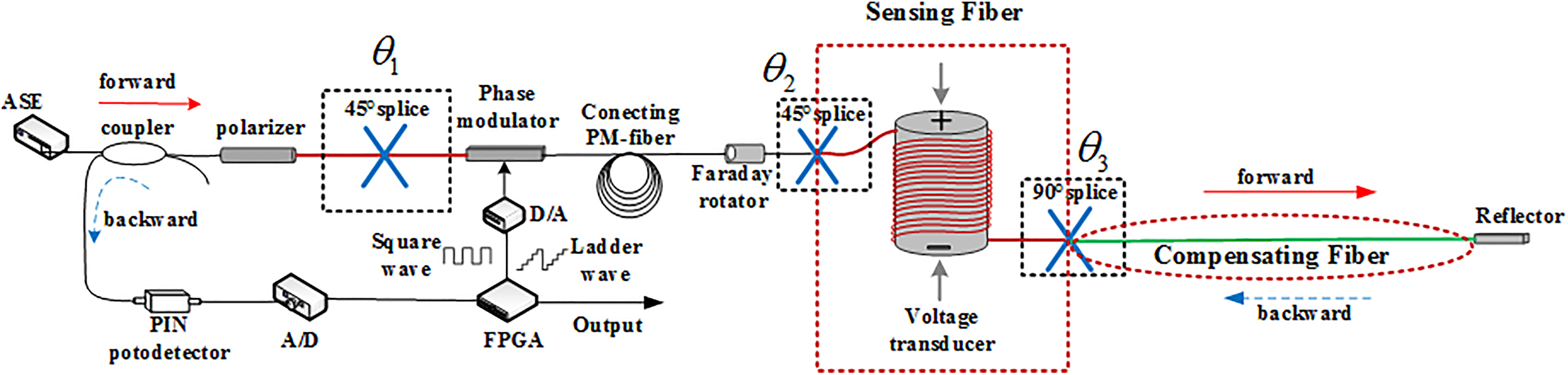
Structure diagram of OVS system. OVS: optical voltage sensor.
Figure 2 shows the transformation process of two orthogonal polarization modes. The system is reciprocity, due to the two orthogonal polarization states transmit along the X-axis and the Y-axis of PMF, respectively. Therefore, there is only the phase modulation signal and phase shift caused by the AC voltage in the ideal output interference signal.

Conversion of two orthogonal polarization modes of polarized light. OVS: optical voltage sensor.
Voltage sensing mechanism
The sensing fiber is wound around the quartz crystal to perceive the piezoelectric deformation of the crystal, which makes the phase shift generated between two orthogonal polarization modes of polarized light. According to Wildermuth et al., 12 the change in the optical wave phase depends on the change of length, the core refractive index, and the core diameter of the sensing fiber. And the phase shift caused by core diameter change can be ignored because it is 2–3 orders of magnitude smaller than the first two terms in the longitudinal strain of optical fiber. 12 As a result, the phase shift caused by the AC voltage is

where β is the optical propagation constant,
The variation of the length of the fiber under the deformation of the quartz crystal is

where Δl is the change of length of single turn sensing fiber; N is the number of turns wound on the quartz crystal by the sensing fiber; Ex
is the intensity of the electric field,
According to Ulrich, 23 the variation of the bending birefringence is

therefore

where κ represents the curvature of fiber bending, 2R is the diameter of the quartz crystal, and 2r is the diameter of the optical fiber.
In summary, the relationship between the piezoelectric phase shift caused by the converse piezoelectric effect and the test voltage is

It can be seen that there is a linear relationship between the test voltage and phase shift. Therefore, the measurement accuracy of the sensor can be judged by calculating the phase shift.
Mathematical model for optical polarization in OVS
The polarization characteristics of each optical element can be expressed by the Jones matrix.
10,13
The expression of light emitted by the ASE (1550 nm) source
where Ex is propagating along the x-axis and Ey is propagating along the y-axis.
Then, the light from the source transmits through the polarizer to form linearly polarized light, and the expression of the polarizer P is

where
Special fiber splices can effectively change the direction of the orthogonal polarization modes.
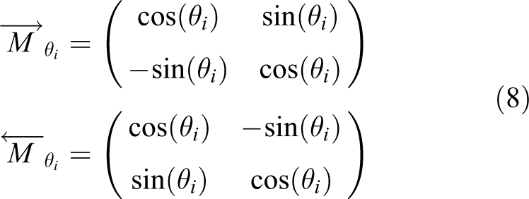
where
The mathematical expressions of the phase modulator T are

where
The Faraday rotator M F that makes the two orthogonal modes is interchanged by changing the polarization plane of the polarized light and offset the phase shift caused by the external environment changes, and the expression is

where
The expression of polarization-maintaining delay fiber M is

where
The sensing fiber

where

where
The expression of the reflector

As stated in the working principle of the OVS, the output of the OVS can be obtained

therefore, the expression of output light intensity is

that is

where
Therefore, the output sinusoidal signal is

and

Mathematical model of output error of OVS
The error caused by external interference can be theoretically offset, but it is difficult to achieve in actual because of the imperfect fiber splice and the length difference between the sensing fiber and the compensating fiber. Therefore, it is crucial to analyze these imperfect factors, because it could introduce system output errors and leads to inaccurate measurements. In this article,

where
Firstly, the output error only caused by the 45° (

where
When a bias phase

and

It can be known that the phase shift caused by the 45° splice between the polarizer and the phase modulator is equal the phase shift in ideal, which cannot introduce an output error (
Then, the influence of another 45° (

sinusoidal transformation of the equation (24)

therefore, the feedback phase can be expressed

From formula (26), it can be concluded that the imperfect 45° splice between the pigtail fiber of Faraday rotator and the sensing fiber can lead the output error of OVS.
In addition, the 90° (

and

where
The feedback phase is

From formula (29), it can be seen that the phase shift caused by the inherent birefringence of sensing fiber mixed with the phase shift caused by the converse piezoelectric effect, resulting in the output error of sensor.
In the end, the influence of the length difference (

and

where
The mathematical model of the feedback phase shift is

From formula (32), it can be seen that the phase shift
Simulation analysis of system output error
According to the established output error mathematical model, the special fiber splice and the length difference between sensing fiber and compensating fiber can affect the measurement accuracy of the OVS system. Combined with the simulation parameters in Table 1, the quantitative analysis of output errors is as follows.
Simulation parameters of the output error.

First of all, from the above analysis that the 45° splice (

The effect of θ 1 OVS’s sensitivity. OVS: optical voltage sensor.
Next, from formula (26), it can be concluded that the 45° splice (
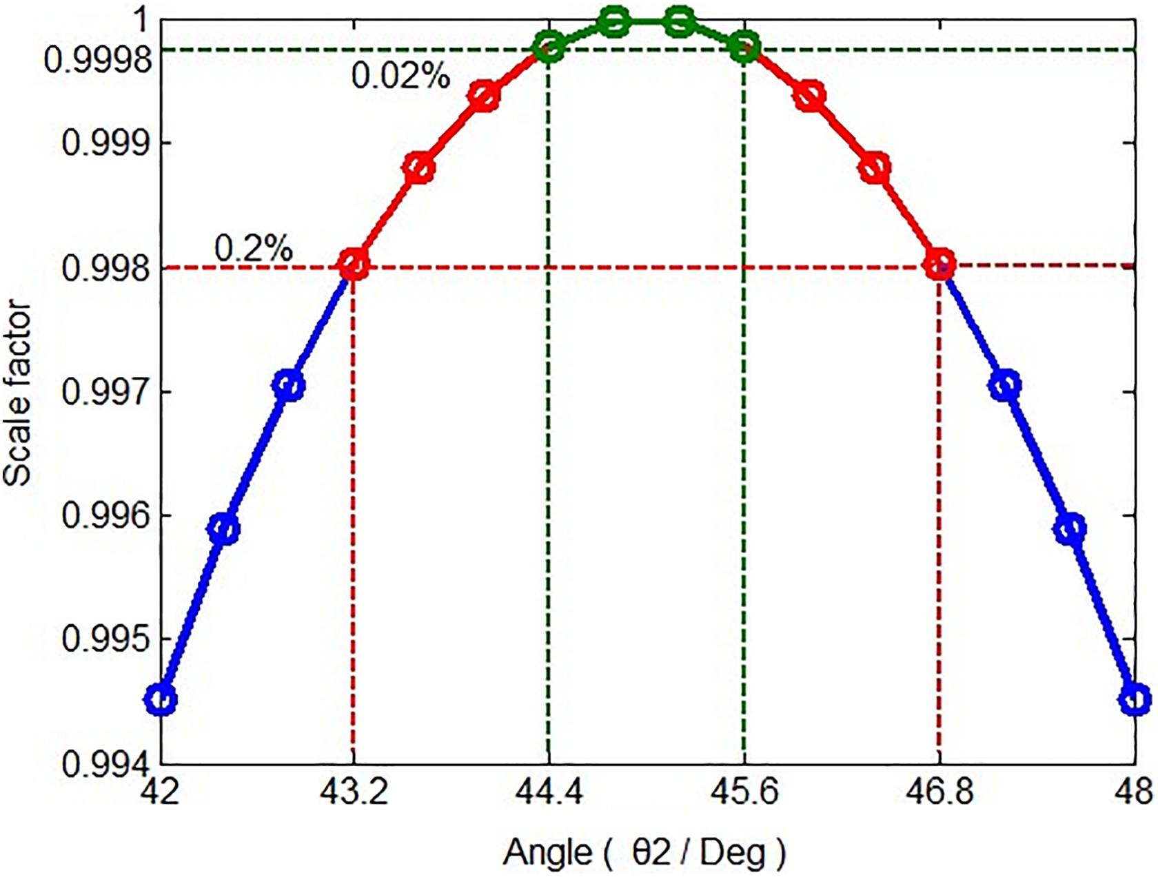
Output errors caused by 45° splice (θ 2).
Then, the 90° splice (

The output error of the OVS system caused by imperfect 90° splice (
The relation between output error and splicing angle (

In the end, the system output error caused by the length difference (
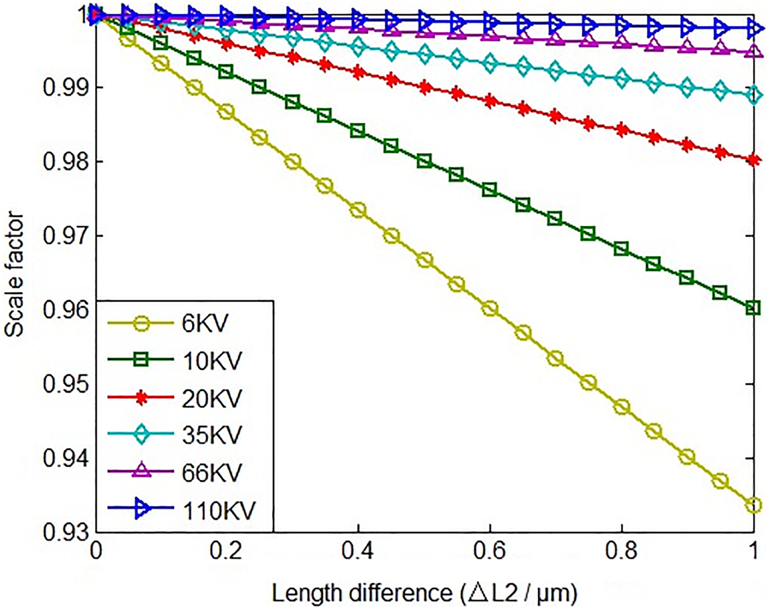
Output error of system caused by (
The relation between output error and length difference (

According to the data in Table 3, the influence of the length difference cannot be ignored. Under the condition of not changing the structure and sensing mechanism, we can suppress the output error from the perspective of fiber itself properties, for example, considering the effects that temperature produces to the PM, we can adopt insensitive polarization-maintaining fiber.
Conclusions
In this article, the relationship among the system output error of optic voltage sensor and the parameters of fiber splicing angle deviation, fiber length difference, and test voltage was studied. The research indicated that different fiber splices have different effects on the system output. Among them, the output error caused by the 45° splice is not affected by the test voltage. And when the splicing angle error is less than 0.6°, the system output error is less than 0.02%. However, the system output error caused by the 90° splice depends on the test voltage. When the test voltage is higher than 6 kV, and its angle deviation is less than 0.15°, the resulting system output error is less than 0.02%. Additionally, the research has also shown that the fiber length difference influences the system output a lot. When the test voltage is 110 kV if the impact of other factors on the system output can be ignored, the length difference between the sensing fiber and the compensating fiber should be less than 1 µm. The research results further deepen the theoretical basis of the all-fiber voltage sensor. And it provides a theoretical basis for the production of optical fiber voltage sensors with different testing voltage requirements and different precision requirements. Especially in the production of the sensor head, it provides a reference for the selection of application parameters of optical fiber. At the same time, it provides reference and new ideas for the design of intelligent inspection robot system for power system under different voltage levels.
Footnotes
Declaration of conflicting interests
The author(s) declared no potential conflicts of interest with respect to the research, authorship, and/or publication of this article.
Funding
The author(s) disclosed receipt of the financial support for the research, authorship, and/or publication of this article: This work was supported by the Youth Science Found Project of National Natural Science Foundation of China under grant no. 6170020319 and the national scholarship to study abroad program under grant no. CSC201708220193.