
Abstract
In most cases, a vehicle works in a complex environment, with working conditions changing frequently. For most model predictive tracking controllers, however, the impacts of some important working conditions, such as speed and road conditions, are not concerned. In this regard, an adaptive model predictive controller is proposed, which improves tracking accuracy and stability compared with general model predictive controllers. First, the proposed controller utilizes the recursive least square algorithm to estimate tire cornering stiffness and road friction coefficient online. Then, the estimated tire cornering stiffness is used to update vehicle dynamics model and the estimated road friction coefficient is used to update the road adhesion constraint. Moreover, the control parameters consist of prediction horizon, control horizon, and sampling time, all of which are set according to vehicle speed. A co-simulation based on MATLAB/Simulink and CarSim is conducted. The simulation results illustrate that the proposed controller has a great adaptive ability to changing working conditions, especially to speed and road conditions.
Introduction
With the rapid growth of city, traffic conditions are getting worse and worse, which leads to frequent traffic accidents. According to statistical data, most traffic accidents are caused by drivers’ operational errors. 1 Autonomous vehicles don’t need drivers’ intervention, so it can reduce the traffic accidents caused by drivers’ misoperation. In recent years, autonomous vehicles have become a hotspot in the field of vehicle engineering and a new driving force for the growth of the automotive industry. Autonomous vehicle is a comprehensive system which integrates environmental perception, 2,3 planning and decision-making, 4,5 motion control, 6,7 human physiology monitoring, 8,9 and other functions.
One of the most basic functions of autonomous vehicles is path tracking. 10 Path tracking control is to control the vehicle to follow a predefined path safely, steadily, and precisely. Obviously, it belongs to the field of lateral motion control. So far, various control algorithms have been applied to this issue. Maalout et al. proposed a fuzzy logic controller for the path tracking of a wheeled mobile robot based on a higher level controller, and the controller can automatically follow a sequence of discrete waypoints. 11 Wang et al. designed a dynamic output-feedback robust controller considering different drivers’ characteristics to assist human drivers for path tracking, which reduced drivers’ delay time and preview time. 12 Hiraoka et al. proposed a four-wheel steering vehicle path tracking controller based on sliding mode control theory. 13 The front- and rear-wheel steering are decoupled, which are adjusted according to the front- and rear-wheel control points, respectively. Chouraqui et al. established an artificial neural network controller to solve the motion planning problem. 14 The input is the distances to the closest obstacles around the vehicle, and the output is the acceleration and steering of the vehicle. Finally, the network is trained with a set of strategic input–output. Nunes et al. proposed a path following controller based on chained system theory. 15 Al-Mayyahi et al. designed an optimal controller and utilized a fractional order proportional integral derivative controller for path tracking. 16 On the whole, all these controllers can achieve the effect of path tracking, but they did not consider some necessary constraints of vehicles, which may lead to problems in vehicle stability and safety.
There are a lot of vehicle dynamics constraints and actuator constraints in the vehicle system. In addition, the greatest advantage of model predictive control (MPC) is its ability to deal with constraints systematically. 17 Therefore, MPC is one of the most widely used algorithms in path tracking of autonomous vehicles. At present, a lot of research on path tracking of autonomous vehicles with MPC have been carried out. Falcone et al. firstly simplified the complex nonlinear vehicle dynamics model to a linear time-varying model, and applied MPC algorithm to track lane-changing trajectory on icing pavement. 18 On the basis of MPC, Chen et al. designed a path tracking controller with a combined model of vehicle kinematics and dynamics. 19 Kim et al. added the actuator dynamics of steering system into the vehicle model and proposed a MPC path tracking controller considering the dynamic characteristics of steering drive system. 20 Lima et al. designed a stable and accurate MPC controller, and the driving smoothness is written into the objective function, which is the minimum of the first- and second-order spatial derivatives of the path curvature. 21 Yang et al. proposed a linear time-varying MPC method based on steering moment input, which combines the electric power steering system with the vehicle dynamics system. Then, it automatically controls the lateral motion of the vehicle by steering motor torque instead of wheel angle. 22 Guo et al. considered the model mismatch induced by varying road conditions and small-angle assumptions as a measurable disturbance and proposed an MPC path following controller with a differential evolution algorithm. 23 All these studies applied MPC algorithm to vehicle control. However, fixed control parameters were used throughout the control process, which might cause unsatisfactory control effect in changing working conditions.
References above did not consider the effect of working conditions on control effects when designing the path tracking controller. In actual driving, however, the environment is complex and working conditions are changeable. Moreover, the control effect demand varies greatly in different situations. For example, in case of high speed, vehicles should give priority to stability, while at a low speed the tracking accuracy should be considered first. Nevertheless, it is difficult for the general MPC controller to adapt to all working conditions. Accordingly, the general MPC controller needs to be improved. Yu et al. used unscented Kalman filter to estimate vehicle state and designed MPC controller based on the estimated vehicle state. 24 The simulation results verified the effectiveness and robustness of state estimation and path tracking. Ercan et al. considered the dynamics of vehicle steering system and identified the parameters of steering system model online with recursive least squares algorithm. 25 Furthermore, an MPC path tracking controller was designed based on the real-time updating model. Chen et al. proposed an adaptive model predictive lane-keeping system based on linear time-varying model. 26 Recursive least square algorithm was used to identify tire cornering stiffness online in real time, and vehicle speed in the prediction layer was predicted by longitudinal acceleration. Although these papers made some improvements for the MPC algorithm, the main contribution was the correction of vehicle model parameters, which often changes slightly in the process of path tracking.
In conclusion, the main goal of this work is to design an adaptive model predictive control (AMPC) path tracking controller, which can adapt to changing working conditions. Since working conditions are mainly reflected on vehicle speed and road friction coefficient, the path tracking controller should satisfy various requirements in case of different speeds and road conditions. To sum up, the contributions of this work are threefold: (1) The estimators of tire cornering stiffness and road friction coefficient are designed to obtain the latest parameters in real time. Then these parameters are fed into the model predictive controller. (2) The impacts of control parameters on control effects are studied. Moreover, three groups of control parameters are designed for different speeds. (3) An AMPC path tracking controller is proposed, whose control effects under changing working conditions is verified by simulation.
The remainder of the paper is organized as follows. The vehicle dynamics model is described in the “Vehicle dynamic model” section. In the “Design of the parameter estimators” section, the estimators of tire cornering stiffness and friction coefficients are designed based on recursive least square algorithm. In the “Design of adaptive model predictive controller” section, the main contributions of this paper are presented, including the control framework, the design of MPC controller and the selection of control parameters. Simulation results of fixed conditions and changing conditions are given and analyzed in the “Simulation and analysis” section, followed by the conclusion in the final section.
Vehicle dynamic model
Different dynamic models can reflect various dynamic responses of the vehicle. It is important to select the appropriate vehicle model for vehicle motion control. Since only the lateral plane motion of vehicles is studied, other motions of the internal mechanism of the vehicle can be neglected. For this reason, the two-degree-of-freedom (2-DOF) vehicle dynamics model is chosen as the research object, which includes lateral motion along y-axis and yaw around z-axis. Figure 1 shows the 2-DOF vehicle dynamics model.

Two-DOF vehicle dynamics model. DOF: degree of freedom.
According to Newton’s second law, the force balance equations along y-axis and around z-axis can be obtained as


where m is the vehicle mass, y is the lateral position of the vehicle,
In this work, the linear tire model is used. Then, the lateral tire force can be calculated by the following equation

where
The side slip angle of front and rear tires are obtained as follows


This research only considers front-wheel steering vehicles, so

Design of the parameter estimators
Estimator of tire cornering stiffness
Lateral force of front and rear tires are calculated according to equations (1) and (2)


The tire cornering stiffness can be estimated by the following equations 27


According to equations (9) and (10), the cornering stiffness of front and rear tires is estimated online by recursive least square algorithm. The system equation for recursive least squares algorithm can be written in general as follows

where
Estimation of road friction coefficient
When the tire is in the low slip range, the adhesion ratio is approximately proportional to the slip, and the relationship is valid for roads with different friction coefficients 28

where Fx
is the longitudinal tire force, Fz
is the vertical tire force,
Equation (12) is substituted into equation (11), in which
After calculating the slope k of the adhesion ratio–slip curve in the low slip range with the recursive least square algorithm, the road friction coefficient can be obtained according to the following equation

where
A simple simulation experiment is carried out to verify the effectiveness of the tire cornering stiffness estimator and the road friction coefficient estimator. The vehicle is made to complete a double-lane change maneuver at an initial speed of 60 km/h. The simulation road is an asphalt road with the friction coefficient of 0.8. The simulation results are shown in Figures 2 and 3.

Estimation of tire cornering stiffness.
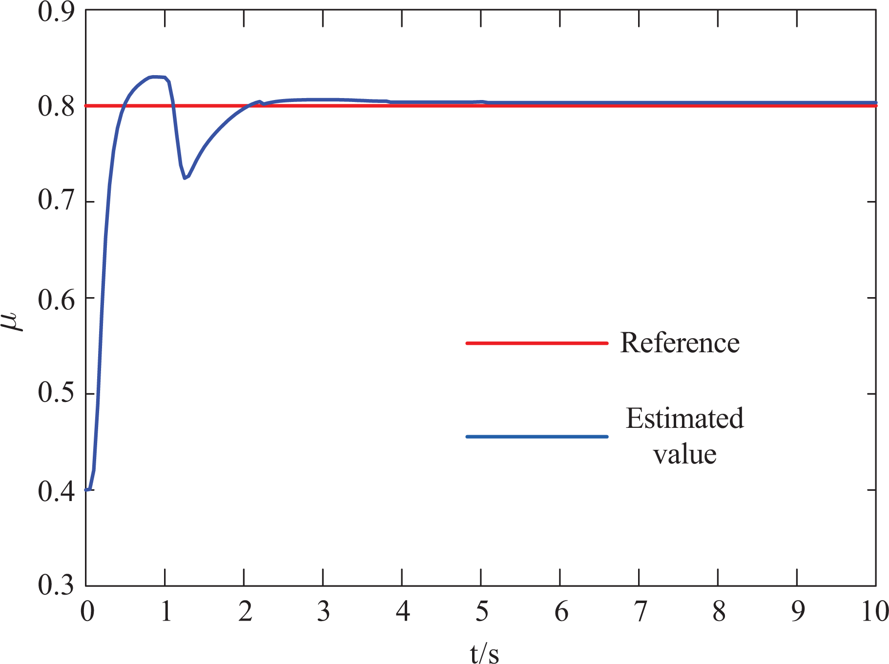
Estimation of road friction coefficient.
As is shown in Figures 2 and 3, the difference between estimated values and reference values is quite small, which shows that the two designed estimators are effective.
Design of adaptive model predictive controller
The structure of the AMPC controller proposed in this work is shown in Figure 4. Expected path can be obtained by sensor detection or vehicle networking system. In this research, we assume that the expected path is known. To improve the robustness to parameter uncertainties in complex environments, the tire cornering stiffness and road friction coefficient are estimated in real time. Then, the estimated tire cornering stiffness is used to update the vehicle dynamics model, which can improve the accuracy of prediction model. Furthermore, the estimated road friction coefficient is used to update the road adhesion constraint in MPC controller, which can promote the adaptive ability to road conditions. At the same time, to improve the adaptive ability to speed, the control parameter selector chooses the suitable control parameters according to vehicle speed. Finally, the MPC controller computes and outputs the current control variables to the vehicle based on the data above.

The structure of controller.
Prediction model
Considering the transformation relationship between the vehicle coordinate and the inertial coordinate, it can be obtained as

Combining equations (6) and (14), we can get

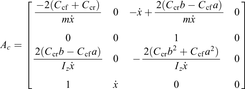
Because the vehicle dynamics model is a nonlinear model, it needs to be linearized into a state space form. Vehicle lateral speed

where


Since MPC algorithm is only applicable to discrete system control, the above continuous system equations need to be discretized
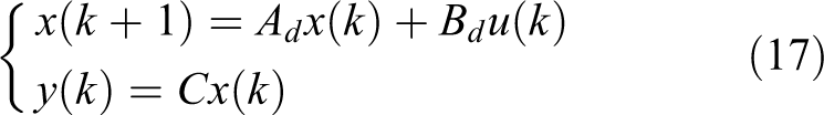
where
On this basis, we assume
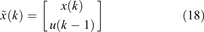
A new state space expression can be obtained as

where

Assuming the system’s prediction horizon is

where


Objective function
The goal of autonomous vehicle lateral control is to track the desired path accurately in real time and to ensure stability and comfort. The objective function is the part that directly reflects the control objective in MPC algorithm. So, it should be in line with the control objective. In this work, the objective function is selected as follows 30

where
The objective function is transformed into a quadratic programming form

where
Constraints
General MPC controller includes three types of constraints: control constraints, control increment constraints, and output constraints. The three constraints above are applied as follows: Control constraints:

Control increment constraints

Output constraints

In addition, the road adhesion constraint is also considered here, which greatly affects the dynamic performance of the vehicle. If the road friction coefficient is too low, the road cannot provide enough driving force, which will cause slide. Therefore, the following constraint needs to be added to the acceleration of the vehicle
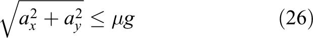
where ax is the longitudinal acceleration, ay is the lateral acceleration, μ is the road friction coefficient, and g is the gravity acceleration.
This research only considers the lateral dynamics of the vehicle, and the longitudinal velocity is assumed to be constant

Because lateral acceleration ay is not a state variable, it needs to be transformed

where
Selection of controller parameters
The parameters that can be selected in MPC controller include prediction horizon, control horizon, sampling time, weight matrix, constraint range, and so on. The three control parameters which have the greatest impacts on control effects are prediction horizon, control horizon, and sampling time. Hence, this research mainly studies these three control parameters. The control effect of the same control parameters differs a lot under different working conditions. With complex and changing working conditions, a group of control parameters is hard to adapt to all working conditions. Therefore, control parameters need to change according to working conditions. This research focuses on the selection of control parameters for different vehicle speeds.
Taking the control parameter
Vehicle trajectory diagram with the same control parameters.
If prediction horizon, control horizon, and sampling time are selected too large, vehicles will be affected by the expected path that is too far away. Moreover, computing load will increase, which will reduce the accuracy of path tracking. If prediction horizon, control horizon, and sampling time are selected too small, vehicles will have difficulty responding to sudden changes in the path, which will cause vehicle stability problems. After a lot of tests, the conclusion is summarized that the higher the speed is, the larger the prediction horizon and sampling time should be. Based on the conclusion above, three groups of control parameters are designed according to vehicle speed, which are suitable for low, medium, and high speed, respectively. The corresponding relationship between the three groups of control parameters and vehicle speeds is shown in Table 1.
Correspondence between control parameters and vehicle speed.

Simulation and analysis
To verify the validity of the proposed AMPC controller, simulations are conducted based on the platform of MATLAB/Simulink, MathWorks Corporation (version 2014b) and CarSim, Mechanical Simulation Corporation (version 8.02). CarSim is used to provide vehicle dynamics model and MATLAB/Simulink is mainly for providing control function. In this section, two types of simulations are carried out, which are fixed conditions and changing conditions. Furthermore, each of them contains two cases. On one hand, simulations of fixed conditions include double-lane change path and varied-road-curvature path, which is to show the path tracking accuracy and stability of vehicles under different conditions. On the other hand, simulations of changing conditions consist of changing friction coefficient road and changing speed, which is to prove the adaptive ability to changing working conditions.
Simulation results of fixed conditions
Double-lane change path
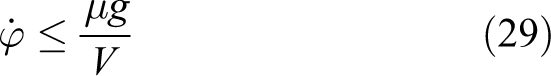
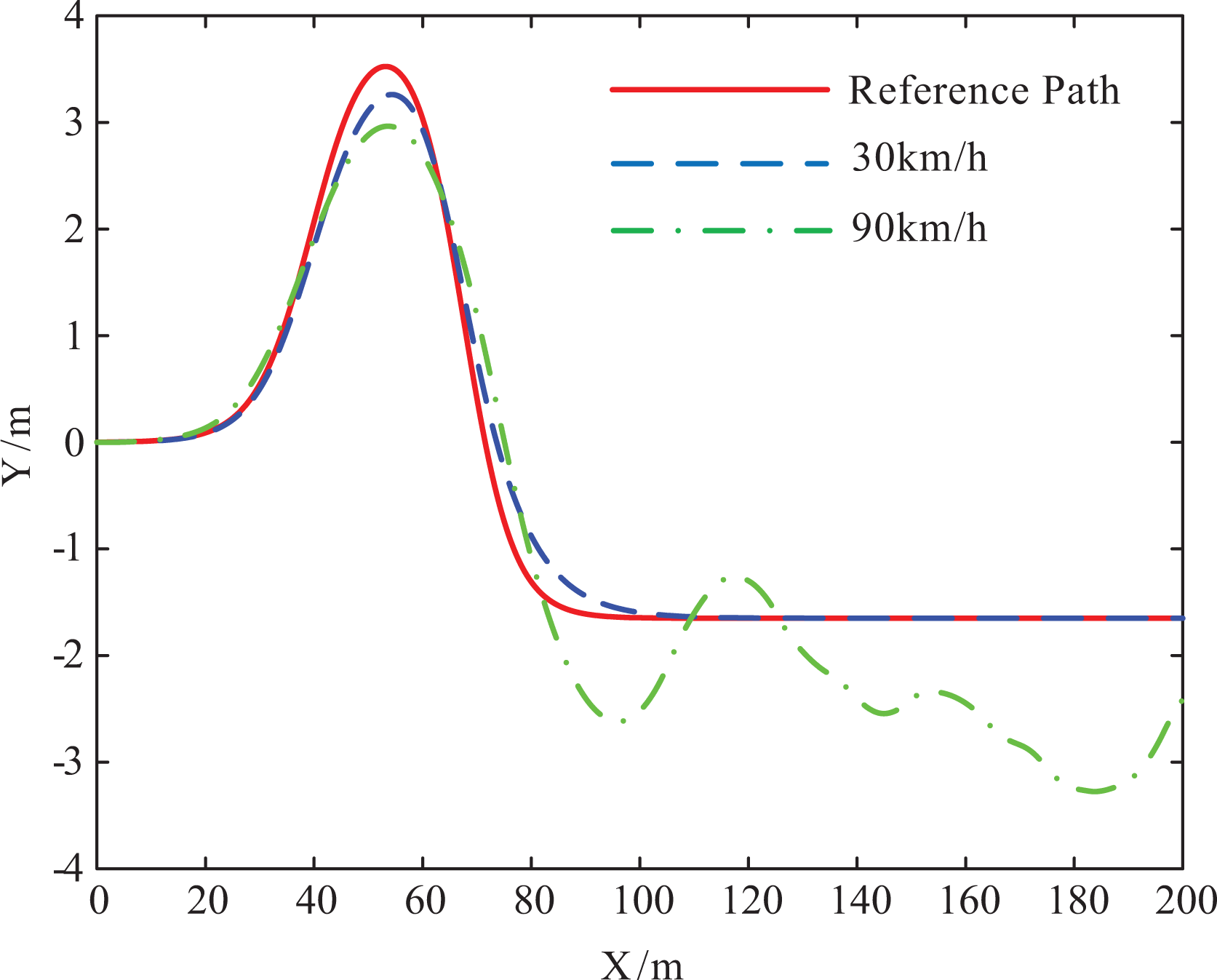
Double-lane change test is one of the international standard tests to test vehicle handling stability, so it is selected as the reference path. In this case, the simulation road is an asphalt road with a road friction coefficient of 0.85. In addition, the vehicle speed is selected 30 km/h and 90 km/h, respectively, to verify the control effect at low and high speeds. The simulation results are shown in Figure 6(a) to (d).

Simulation results of double-lane change path: (a) vehicle trajectory, (b) front-wheel angle, (c) yaw rate, and (d) sideslip angle.
From Figure 6(a) to (d), it can be seen that the controller designed in this work has high tracking accuracy at a speed of 30 km/h, with a maximum error of only 0.1 m. On the other hand, the tracking accuracy decreases at a speed of 90 km/h with the maximum error of about 1 m. Considering the high speed of the vehicle, the error is within the acceptable range. During the double-lane change test, the maximum error usually occurs in the two bends which are in the longitudinal position of 60 m and 80 m. However, the errors in other positions are small. Obviously, the reason is that the curvature of these two positions changes rapidly, so the vehicle fails to respond in time. Moreover, the change of front-wheel angle is stable at 30 km/h and 90 km/h with no large sudden change and jitter. The front-wheel angle at 90 km/h is less than that of 30 km/h, which is conducive to improving vehicle stability. In addition, the yaw rate and sideslip angle do not fluctuate significantly at 30 km/h and 90 km/h, and they are far less than the constraint limit, which indicates the great vehicle stability.
In summary, the AMPC controller designed in this work can ensure the stability of vehicles at any speed. At the same time, it has high tracking accuracy at a low speed, while the tracking accuracy decreases a little at a high speed.
Varied-road-curvature path
To further verify the effectiveness of the proposed AMPC controller subject to roads with different curvatures, a path following case with the varied road curvature is performed in this subsection. In this maneuver, the curvature of the reference path ρ = 0.02 m−1 when the longitudinal position X < 50 m, else ρ = 0.01 m−1. On an asphalt road with a road friction coefficient of 0.85, the vehicle travels at speeds of 30 km/h and 90 km/h.
The results of path following performance are indicated in Figure 7(a) to (d), from which it illustrates the validity of the proposed AMPC controller on different curvature paths. As we can see in Figure 7(a) to (d), the path tracking errors are really small during the whole process at a speed of 30 km/h. The front-wheel angle changes stably, as well as the yaw rate and the sideslip angle. When the speed is 90 km/h, the AMPC controller makes the front-wheel angle change rapidly to ensure better tracking accuracy when the curvature of the reference path changes. Therefore, the front-wheel angle fluctuates greatly at the junction of two different curvature paths, which also causes the fluctuations of yaw rate and sideslip angle. In a short period of time, however, it returns to a stable state. In general, the front-wheel angle is still controllable. In summary, the AMPC controller designed in this work can follow the reference path with different curvatures stably and accurately.

Simulation results of varied-road-curvature path: (a) vehicle trajectory, (b) front-wheel angle, (c) yaw rate, and (d) sideslip angle.
Simulation results of changing conditions
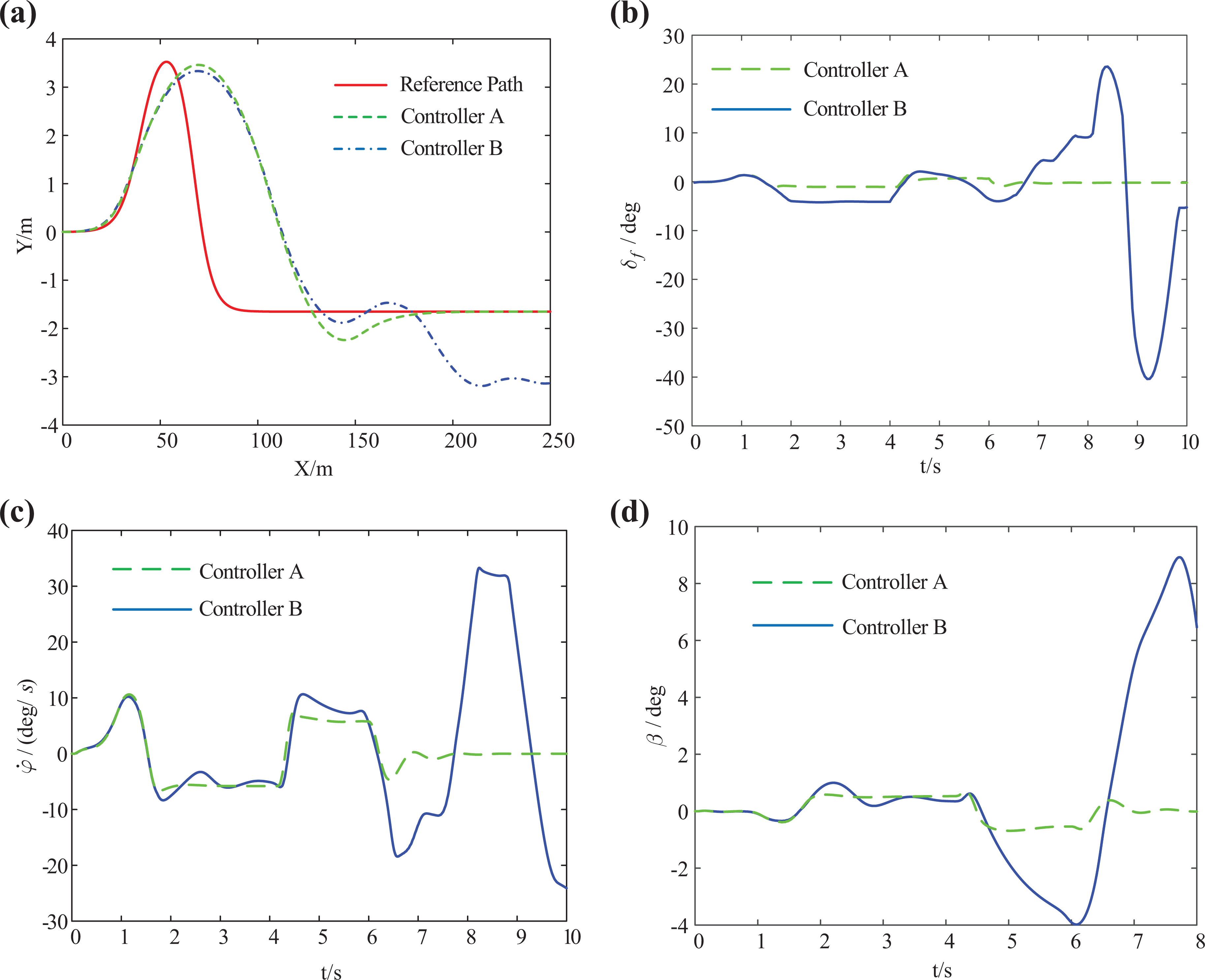
To show the advantage of the proposed controller, the proposed AMPC controller is marked as controller A, and the general MPC controller without parameter estimation and control parameter selection is marked as controller B. Then, the control effects of controller A and controller B under the same conditions are compared.
Changing friction coefficient
To verify the adaptive function of the controller to road conditions, a road with changing friction coefficient is selected as the test road. In more detail, the road friction coefficient is 0.85 when the longitudinal position is 0–40 m and 0.3 when the longitudinal position is over 40 m. The vehicle is made to complete a double-lane change maneuver at a speed of 90 km/s. The simulation results are shown in Figure 8(a) to (d).
Simulation results of changing friction coefficient road: (a) vehicle trajectory, (b) front-wheel angle, (c) yaw rate, and (d) sideslip angle.
From Figure 8(a) to (d), it can be seen that due to the good road condition, the performance of controllers A and B is basically the same when the vehicle is in the longitudinal position of 0–40 m. When the longitudinal position exceeds 40 m, the road friction coefficient changes from 0.85 to 0.3. Meanwhile, the yaw rate and sideslip angle of controller A are obviously lower than those of controller B, and finally it can enter a stable state. This is because controller A detects the change of the road friction coefficient through the parameter estimator and adjusts the road adhesion constraints. As a result, it can ensure that the vehicle state satisfies the constraint of the road adhesion condition. However, with no parameter estimation module, the controller B still works the same as before when the road friction coefficient changes abruptly, which leads to vehicle state exceeding the road adhesion limit. What’s more, it causes vehicle sideslip and loss of control eventually.
In conclusion, when the road condition changes, the AMPC controller A has better stability and path tracking performance than the general MPC controller B, which proves the adaptive ability of the AMPC controller.
Changing speed
To verify the adaptive ability of the AMPC controller to speed, the simulation speed rises from 30 km/h to 90 km/h in 0–10 s, and then keeps a constant speed of 90 km/h, as shown in Figure 9. The simulation road is an asphalt road with friction coefficient of 0.85, and a sinusoidal curve is chosen as the reference path. The simulation results are shown in Figure 10(a) to (d).

Diagram of changing speed.
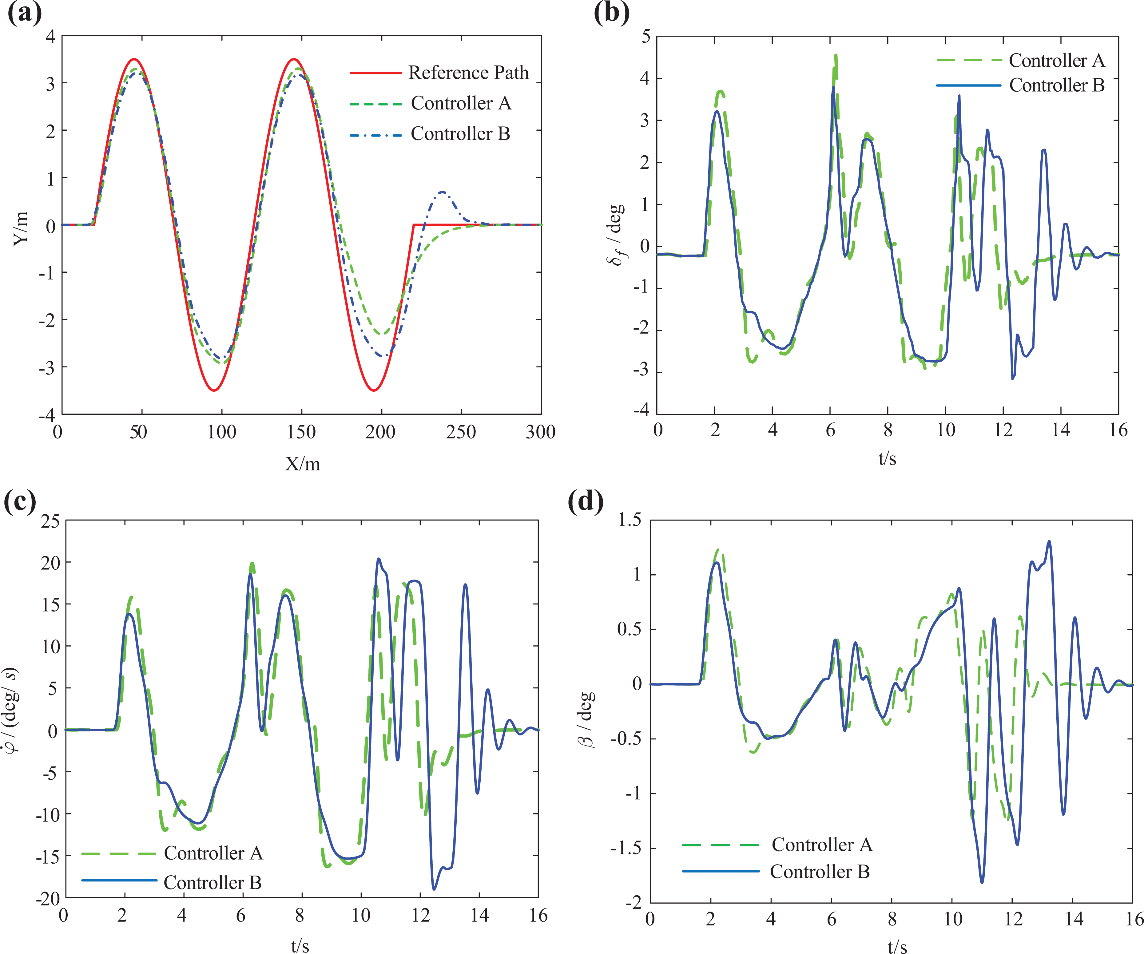
Simulation results of changing speed: (a) vehicle trajectory, (b) front-wheel angle, (c) yaw rate, and (d) sideslip angle.
As is shown in Figure 10(a) to (d), the path tracking accuracy of controller A is better than that of controller B in the longitudinal position of 0–180 m. Considering the low speed during this period, the tracking accuracy is improved greatly. When the longitudinal position is over 180 m, the path tracking error of controller A is larger than that of controller B. However, the yaw rate and sideslip angle of controller A is smaller, which means better stability. Moreover, controller B produces a large overshoot and a jitter at the last turning, while controller A can enter the stable state smoothly.
To sum up, controller A has better path tracking accuracy at a medium or low speed compared with controller B. On the other hand, the vehicle stability of controller A is better at a high speed. Considering that there is no serious problem of stability at a low speed, we should pay attention to the path tracking performance at this time. However, at a high speed vehicles are prone to lose stability. Once the vehicle is unstable, the consequences are very serious. For this reason, the stability of the vehicle should be given priority at this time. To meet the requirements above, the designed AMPC controller can select the suitable control parameters according to different speeds.
Conclusion
In this work, an AMPC controller is designed for path tracking in changeable working conditions. First, on the basis of the general MPC controller, the estimators of tire cornering stiffness and road friction coefficient are added, as well as the control parameter selection module. Moreover, the estimated tire cornering stiffness and road friction coefficient are used to update the vehicle model and road adhesion constraints respectively, which improves path tracking accuracy and stability. Also, the control parameter selector sets the suitable control parameters according to vehicle speed. Finally, the simulation results show that the proposed AMPC path tracking controller not only ensures good path tracking accuracy and stability but also has a great adaptive ability to changing working conditions, especially to speed and road conditions. Devoted to the precise control of path following, the path tracking performance at a high speed should be improved in future works.
Footnotes
Declaration of conflicting interests
The author(s) declared no potential conflicts of interest with respect to the research, authorship, and/or publication of this article.
Funding
The author(s) disclosed receipt of the following financial support for the research, authorship, and/or publication of this article: This work was supported by National Natural Science Foundation of China (grant no. 11672127), China Postdoctoral Science Foundation (grant nos 2017T100365, 2016M601799), Fundamental Research Funds for the Central Universities of China (grant no. NT2018002), and Open Foundation for Graduate Innovation Base (Laboratory) of Nanjing University of Aeronautics and Astronautics (grant no. kfjj20180207).