
Abstract
In this article, a method for calibrating the relative position between dual two-dimensional laser range finders is proposed. This relative position is affected by the manufacture or assembling error of mobile platform, and this error could reduce the accuracy of localization. This article focuses on three-degree-of-freedom calibration, that is, one rotational and two translational degrees of freedom. The entire calibration process can be summed up into three steps. The first step is to allow the dual finders to scan one corner at the same time and then extract the parameters of the corner. The second step is to establish a cost function which is established according to the direction vector of the line and the repeatability of the corners. With this function, the genetic algorithm is used to obtain the final calibration result. Moreover, the finder systematic error and the statistical error are also considered into this article. Simulations and experiments are carried out to verify the proposed method.
Introduction
A mobile manipulator with extended mobility can be utilized in various applications, such as drilling/riveting in aircraft manufacturing, baseline drawing in decoration engineering, and nuclear reactor maintenance. 1 –5 There are several issues associated with mobile manipulator, and localization is the most important one. In view of localization with laser range finder, dual sensors mounted on the two corners of the mobile platform is the common form. 6 –9 If the relative position between dual finders cannot be accurate, the error of the data registration between the dual finders will be caused, and the final accuracy of localization will be reduced. Under such circumstances, the calibration of dual two-dimensional (2-D) laser range finders is an issue which is not fully researched.
To solve this issue, many researchers have implemented various algorithms. These algorithms can be classified into three categories. The first one is using calibrate target. The second one is with camera aided, while the last one is with rotating platform. Chen et al. 10 developed a calibration algorithm that a 3-D orthogonal spatial target was used to obtain the relative position and orientation of dual laser range finders. Antone and Friedman 11 also used homemade pyramid targets to obtain the position and orientation of laser range finder relative to a fixed coordinate system.
With regard to camera-aided calibration, Gomez-Ojeda et al. 12 presented a new approach which relied on the observations of orthogonal trihedrons. This method does not require any specific pattern, making the calibration process fast and simpler to perform. Kurnianggoro et al. 13 also utilized a camera to scan several poses of a planar checkerboard. The axis and radius of rotation were extracted by solving a linear equation constructed from the point-plane constraint. A different strategy was proposed by Taylor et al., 14 which was applied to the extrinsic parameters calibration of camera-finder system. The scan of finder was projected onto the camera’s image using a camera model, and particle swarm optimization was used to find the optimal parameters.
In terms of rotating platform-aided calibration, Kang and Doh 15 proposed a calibration method that estimated full degrees of freedom (DOF) between two 2-D laser range finders and the rotating platform. This method only used a simple plane without any other additional hardware. The key concept was a decoupling property, with which an original 6-DOF problem was decoupled into two 3-DOF estimation problems. Another algorithm proposed by Fan et al. 16 was to calibrate parameters between the 2-D laser range finder and the platform. A calibration board with right angle outline was designed to improve the calibration accuracy based on the line feature, and the 3-D reconstruction experiment of real data proved the effectiveness of the system and the algorithm. A novel technique for calibrating a multimodal sensor system has been developed by Sheehan et al. 17 which used the Rényi’s quadratic entropy-based calibration algorithm with multiple 2-D laser range finders on a rolling plate. In this method, the plate and laser range finders are assumed to be parallel. Only1-DOF-rotation and 2-DOF-translation on the plate were considered.
Based on the former analyses, it can be concluded that for the calibration of dual finders, most rely on external devices such as precise calibration target, camera, or rotating platform. In this article, a new calibration method based on a common internal corner, which can avoid the need of specific calibration patterns, is proposed.
Problem formulation
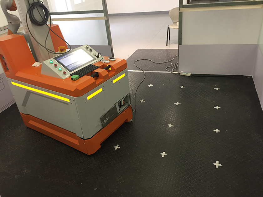
The localization is a crucial function for mobile manipulator. As shown in Figure 1, this mobile manipulator is used for drilling/riveting on the rocket fuselage. The working range of one laser range finder is 270°. To extract 360° environmental information around the robot, dual 2-D laser range finders were symmetrically distributed in the opposite corners of the mobile platform. They scanned the reflectors preset in the environment and then self-localized. As shown in Figure 2, Mobile Manipulator in Construction (MoMaCo) is developed by Shanghai University for drawing baseline in architectural decoration engineering. This system scanned the indoor environment and used the internal corner as feature for self-localization.
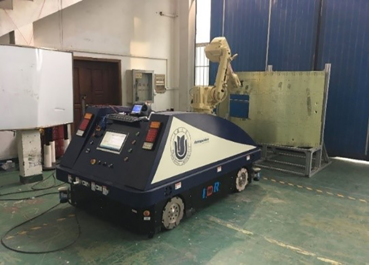
Mobile manipulator for drilling/riveting on the rocket fuselage.
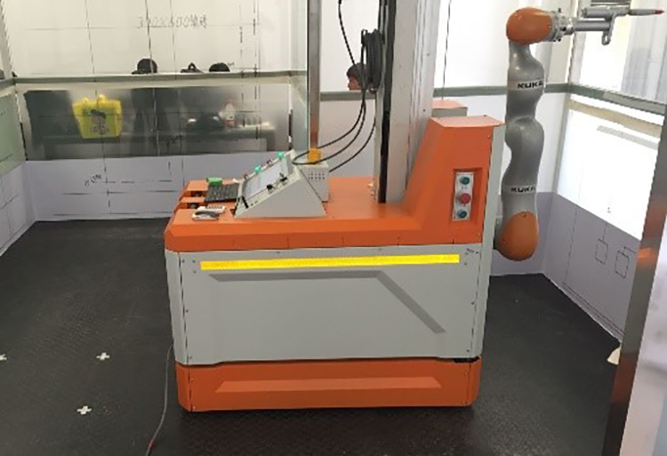
MoMaCo. MoMaCo: Mobile Manipulator in Construction.
For such mobile manipulators as shown in Figures 1 and 2, the accuracy of localization is affected by three factors. The first one is scanning accuracy of laser range finders. The second one is algorithm of localization. The last one is calibration between dual finders. The principle of calibration can be seen in Figure 3.

The principle of calibration.
The frame {X
P, Y
P, Z
P} is attached to the center point of the mobile platform. Dual laser range finder frames {X
L1, Y
L1, Z
L1} and {X
L2, Y
L2, Z
L2} are attached to the left-front and right-rear positions of mobile platform, respectively. The calibration can be defined as the determination of two constant vectors, that is, 3-D rotations (
Localization modeling
The localization of MoMaCo can be classified into two cases, first with single laser range finder and the other with dual finders. While single finder can scan 270° in the horizontal plane, dual finders as a combination can scan 360°. The first case localizes with partial environmental information, while the second case localizes with full environmental information. In the following section, the modeling of these two cases will be presented.
Single laser range finder case
The localization with singe finder can be carried out, while at least three features can be recognized as shown in Figure 4.

Localization with single finder.
Localization with single finder can be divided into nine steps. The first is laser scanning in which the raw data can be obtained directly from finder. The second step is data preprocessing, and the raw data in polar form can be transferred into Cartesian form. The third step is filtering that with Median method to remove noise. The fourth step is clustering. Clustering is to use the spatial proximity method to classify the reflection points of the same object into one class. 18 The fifth step is line segmentation. 19,20 With this step, the environmental information can be divided into line and non-line features, and the valid lines will be extracted. The sixth step is line fitting with the least squares total error algorithm. 21 The seventh step is the feature point extraction. The MoMaCo usually works indoors for decoration engineering, so the corner is an ideal feature for localization. The eighth step is feature point matching. 22,23 The relationship between local coordinates and global coordinates of feature points can be obtained. The last step is pose calculation based on the principle of three-sided positioning. If there are more than three features that can be recognized, the pose calculation can be carried out with the least square method.
Dual laser range finders case
Contrast with the single finder case, localization with dual finders uses full environmental information, as shown in Figure 5. All the feature points in the environment can be applied into the localization.

Localization with dual finders.
Localization with dual finders can be divided into 10 steps as shown in Figure 6. Localization with dual finders need another step of data registration before clustering. Date registration is to combine the data from dual finders into one data set by coordinate transform. The quality of data registration involves the accuracy of relative position between dual finders, so calibration between dual finders is a significant step to improve the accuracy of localization.
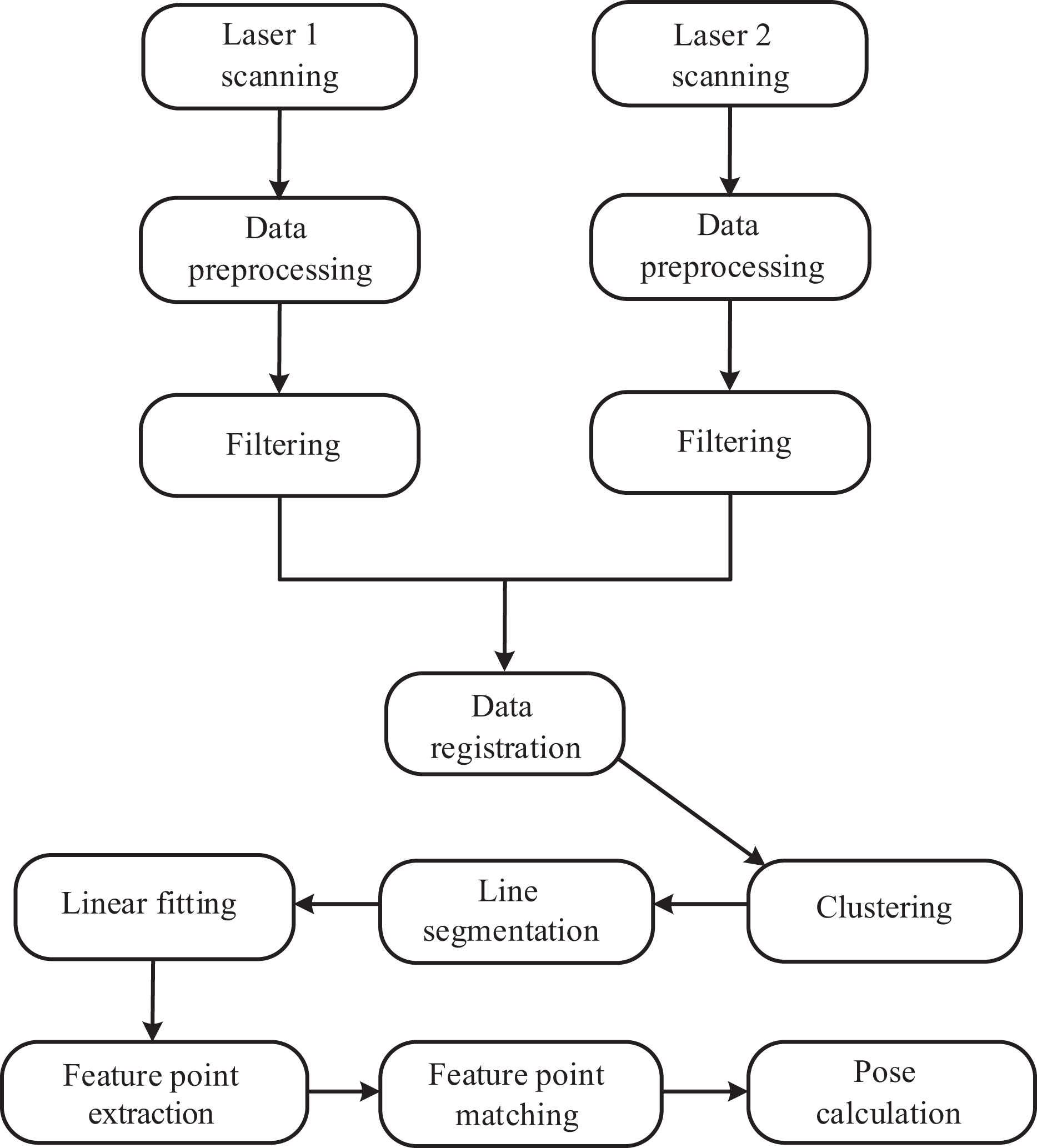
Flowchart of localization with dual finders.
Modeling of calibration
For calibration purpose, the process should be simple and easy to implement, while the results can be still accurate. As in the literature, 24 it requires the lasers to observe a common planar. In this article, the calibration process only relies on an internal corner in the room.
As mentioned in the “Problem formulation” section, three parameters (ωz , tx , and ty ) are the ones to be calibrated. At the same time, the other three parameters (ωx , ωy , and tz ). can be considered as ideal ones.
As shown in Figure 7, calibration can be carried out by finding the relationship between dual finders with the same object. To be specific, the internal corners are selected because they are common and stable. L1m1 and L2m1 are the line m1 in L1 frame and L2 frame individually, while L1m2 and L2m2 are the line m2 in L1 frame and L2 frame individually. The calibration between dual finders can be obtained using these lines which form the corner. The main process of calibration is shown in Figure 8.
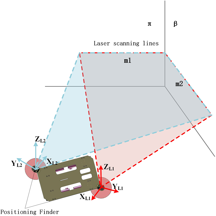
Calibration scene.
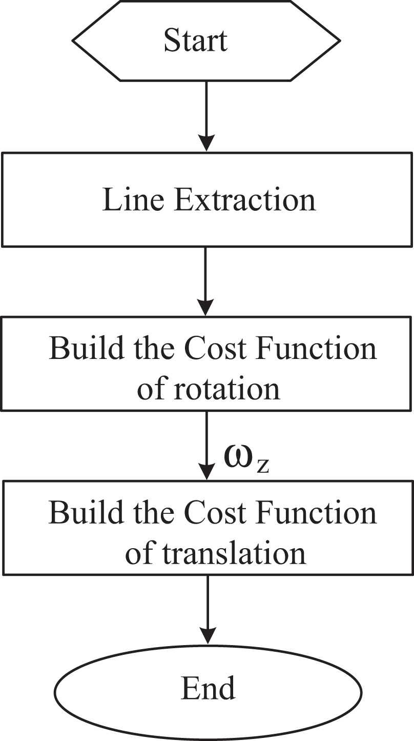
Flowchart of calibration.
The first step is line extraction, in which the corner will be scanned by dual finders to obtain the lines m1 and m2. As shown in Figure 9, single finder scans (


Single finder scanning.
The finder is easily affected by the surface characteristics of the object or the light source interference from the environment which causes a noise disturbance in the scanning data. To solve this problem, the line (m) can be obtained with the total least squares algorithm in the form of ax + by + c = 0. The symbols with hat hereinafter mean that they come from fitted line, for example,
The unit direction vector of line

Next, the rotation parameter
The second step is to build the cost function of rotation. With equation (2),

where


The last step is to build the cost function of translation. While


tx and ty can be obtained using equation (9)

At this point,
Experiments
Experiment setup
To verify the effectiveness of abovementioned algorithm, the calibration experiments were carried out. As shown in Figure 10, in a 2 × 2 m2 area, a 4 × 4 grid is arranged. Each smallest square has a side with the length of 0.5 m.

(a and b) Experiment scene.
According to Ye and Borenstein, 25 the laser range finder has drift effect. To reduce it, the data were acquired after at least 2 h since activation. Commonly, systematic error of the finder is related to its scanning distance. To eliminate the influence of this factor, many different situations of experiments were carried out to obtain a comprehensive calibration result. There are 16 experimental positions in total. Considering the statistical error of the sensor, the number of experiments at per position is 100.
Experimental results
Calibration was conducted at all 16 target positions, with

Value of tx in different positions.

Value of ty in different positions.

Value of
According to Figures 11 to 13, it can be found that the results in the position 5, 9, and 13 fluctuate larger than the results in other positions. This is mainly affected by the length of the target line in scanning field. During the data computing, the short one of the two scanning lines on one wall from two finders is considered as the length of the target line. As shown in Figure 14, the green lines represent the two target lines. At this position, finder 2 is close to wall 2, which leads to that finder 2 cannot scan the whole wall 1. It is the same to the positions 9 and 13. As listed in Table 1, it can be seen that, when the system is in these three positions (underlined in Table 1), the length of the target line in wall 1 from finder 2 is shorter than the others. It should be noted that at a small amount of scanning positions short target line will result into inaccuracy of the fitted line.

Scanning diagram on the position 5.
Length of the walls in two finders’ scanning field (mm).

To solve this problem, the experiments in positions 5, 9, and 13 are removed directly in the following process. From the selected data, it can be found that tx
, ty
, and
Optimization
Based on the analysis in the “Experiments” section, there are still some small differences on
As shown in Figure 15, for the same wall S1, L2S1 is the line obtained by finder 2 and

A schematic diagram of LAB.

The representation of LAB in (a) parallel and (b) intersecting cases.


The final objective function is shown in equation (13)

While Set Calculate Continue step 2 till the termination condition is met, that is, iterative generation k ≥ ε.

Flowchart of genetic algorithm.
The optimization is implemented using the MATLAB® 2016b genetic algorithm toolbox. The optimized results are
Two kinds of validation experiments are designed. The first kind keeps the same orientations of the robot at 13 positions. The second is to make the robot in different orientations and is shown in Figure 18.
MoMaCo in experiments. MoMaCo: Mobile Manipulator in Construction.
As shown in Appendix, both the optimized parameters and the design parameters (un-optimized,
Conclusion
In this article, one method is proposed for the calibration between dual 2-D laser range finders, which avoids the need for specific calibration patterns. This method is based on only one internal corner. The main process is summed up as follows: In the first step, the cost equation of rotation is established according to the direction vector of scanning line, while the translational cost equation is established based on the coincidence of the same corner. In the process of calibration, the effect of the finder systematic error and the statistical error is considered with the conclusion that the systematic error of the finder has not to be considered in a 2 ×2 m2 area. The statistical error is reduced by mean value obtained in multiple experiments. The optimized target equation is established based on the foot point, and the significance of the target equation is analyzed. Finally, the genetic algorithm is used to find the optimal value, and the effectiveness of the method is proved by the experiment. The proposed method has been applied to optimize the calibration parameters of MoMaCo. Figure 19 shows that MoMaCo was working on drawing baselines in decoration engineering. In actual use, the system’s accuracy of localization is well guaranteed.

MoMaCo was working on drawing baselines. MoMaCo: Mobile Manipulator in Construction.
Footnotes
Declaration of conflicting interests
The author(s) declared no potential conflicts of interest with respect to the research, authorship, and/or publication of this article.
Funding
The author(s) disclosed the receipt of the following financial support for the research, authorship, and/or publication of this article: This work was supported by the National Natural Science Foundation of China (No. 61803251, 51775322).
Appendix 1
Results of optimization and no optimization at different positions—Figure (a): position 1, Figure (b): position 2, Figure (c): position 3, Figure (d): position 4, Figure (e): position 6, Figure (f): position 7, Figure (g): position 8, Figure (h): position 10, Figure (i): position 11, Figure (j): position 12, Figure (k): position 14, Figure (l): position 15, Figure (m): position 16. Figures (n) to (s) are the results of different orientations.