
Abstract
In order to design an ocean wave energy generator robot, a novel wave energy converter with parallel mechanism is designed and analyzed. A creative thinking that parallel mechanism can be applied to the wave energy converter is presented and verified during the wave energy using process. The design principles of the wave energy converter are given according to wave motion characteristics. Based on the principles, a novel wave energy converter with 4UPS/UP parallel mechanism is designed, which includes the design of the parallel mechanism, hydraulic cylinders, oil circuit, and converter integration. Then the kinematics model and statics model of the wave energy converter with 4UPS/UP parallel mechanism are derived by MATLAB and ADAMS; with these two methods, we found that the errors of rod length, velocity, and acceleration were 1.13 mm, 0.04 mm/s, and 0.38 mm/s2, respectively. Maximum stress error and maximum constraint moment errors were 1.52 N and 0.57 N·mm. So the correctness of the models is verified. This article can not only provide a reference for other types of parallel mechanisms applied to the wave energy converter, but also provide a theoretical foundation for the experimental prototype and practical application of the wave energy converter.
Introduction
With the development of the industry and economy, human demand for energy is increasing day by day, the development and utilization of new energy becomes an urgent problem at present. 1 The ocean covers 71% of the earth surface, and it contains a large amount of renewable energy like wind energy, tidal energy, wave energy, tidal current energy, thermal energy, and salinity energy. The wave energy produced in 1 year is equivalent to the global energy consumption. 2,3
There are many kinds of wave energy converters such as oscillating water column, pendulum wave energy converter, raft type wave energy converter, submerged pressure differential wave energy converter, and nodding duck wave energy converter. 4 –6 Different converters have their merits and defects. With the advantage of simple structure and reliable performance, the oscillating water column is seen as a more thorough converter, but in terms of conversion efficiency and reducing cost, it still needs to be improved. 7 The pendulum wave energy converter has high energy conversion efficiency and low construction cost, but its conversion efficiency is not stable and its equipment is easy to be damaged. 8 There is a keen desire for the development of a converter with high conversion efficiency, stable structure, and low construction cost. Accordingly, nowadays, it has become a hot research area to design a new and high feasibility wave energy converter.
Parallel mechanisms have the advantages of high stiffness, high carrying capacity, and large payload to mass ratio. 9 –12 This type of mechanism draws attentions of quite a few researchers. Wu et al. proposed a two-axis-decoupled solar tracker based on a parallel mechanism in terms of innovative application. 13 If the parallel mechanism is applied to wave energy utilization, it is possible to use multiple hydraulic cylinders to convert the wave energy and as a result, the energy conversion efficiency of the wave energy converter can be greatly improved. Besides, each of the hydraulic cylinders’ branched chain has high carrying capacity, so the stability of the wave energy converter can be greatly improved. In the current study, there are few schemes to apply parallel mechanism into the wave energy converter. Wang et al. 14 and Qian et al. 15 are trying to use 6-degree-of freedom (DOF) parallel mechanism as the energy converter. The 6-DOF parallel mechanism can absorb the wave energy from all directions in theory, but in practice, too many DOFs applied in the process of wave energy transformation, will reduce the stability of converters and increase the motion uncertainty of the mechanism. Hyun and Jun 16 carried out static analysis of 6-DOF parallel mechanism and identified the dynamic characteristics of parallel mechanism by modal analysis based on linear mapping matrix. Yang and Yimin 17 analyzed the position, velocity, and acceleration of 2-DOF parallel mechanism. Then, the kinematic characteristics of other components of the mechanism are derived by using the principle of superposition.
The contribution of this manuscript is the novel wave energy converter with 4UPS/UP parallel mechanism is designed and analyzed, and the creative thinking that parallel mechanism can be applied to the wave energy converter is presented and verified. In this article, the principles during the design process of the wave energy converter are given according to wave motion characteristics and a novel wave energy converter with 4UPS/UP parallel mechanism is proposed. 18 The kinematics and statics of the parallel mechanism are analyzed and calculation examples are given to verify the correctness of the kinematic and static analysis. This article is organized as follows. The second section introduces the design principles and structure of the energy converter. Then, the third section introduces the kinematic analysis for the 4UPS/UP parallel mechanism in the converter. The establishment of the static model and the derivation of stress expressions for hydraulic cylinders are established in the fourth section. In the fifth section, some calculation examples for the parallel mechanism are presented to verify the correctness of analysis results obtained in the third and fourth sections. Finally, the sixth section presents the conclusions and further work.
Design of the novel wave energy converter
This article proposes creative thinking that parallel mechanisms can be used in wave energy converters. In the design process of the wave energy converter, the specific conditions of waves must be considered. This section mainly introduces the design principle and the design process of the novel wave energy converter with the parallel mechanisms. As a special instance, a novel wave energy converter with 4UPS/UP parallel mechanism was designed. This section can provide a reference for other types of parallel mechanism applied to the wave energy converter.
Design principles of wave energy converter
In this article, the wave motion equation is assumed as two-dimensional small amplitude wave equation. The form of the two-dimensional small amplitude wave is shown in Figure 1, from which we can see that the wave motion appears as simple harmonic motion with propagating at a certain speed.
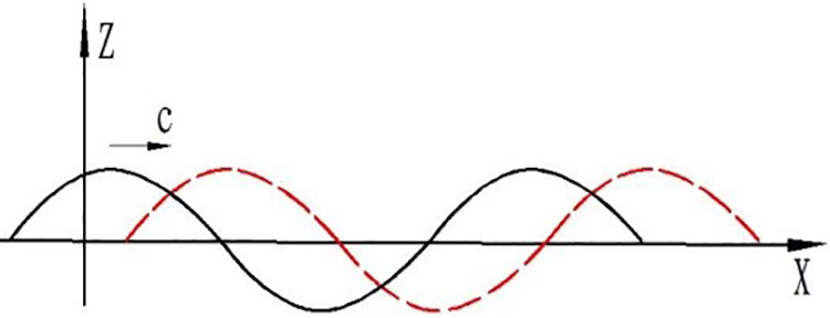
Form of the wave.
And the wave motion equation is

where H is the wave height; L is the wavelength; T is the wave period; x is the wave propagation distance, and
Considering the form and equation of the wave, the wave energy consists two parts: one is from the wave vertical vibration and the other one is from wave impact. The influence caused by these two parts of energy is very huge. Due to the complexity of wave motion, the wave impact direction is uncertain. Considering these factors, some principles must be followed in the design process of the wave energy converter with parallel mechanisms.
The appropriate DOF
For the sake of high energy conversion efficiency, it is necessary for the wave energy converter to absorb both the wave vertical vibration energy and the wave impact energy at the same time, and adapt to the uncertainty of wave motion. Therefore, the converter has at least three DOFs. Nevertheless, the DOF of the converter can’t be too high so that it can run steady, so the most appropriate DOFs are three.
Redundant parallel mechanisms perform better
Redundant parallel mechanism is a kind of parallel mechanism whose number of branched chain exceeded its DOF. Compared with non-underactuated robot, 19 this kind of mechanism has the advantages of high stiffness and excellent load capacity. When the DOF of the wave energy converter is determined, more hydraulic cylinders can obviously improve the conversion efficiency, so it’s better to choose redundant parallel mechanisms.
The security and stability
In the process of actual operation, the wave energy converter should be able to adapt to the harsh marine environment and minimize pollution to the marine environment. In addition, it is necessary to avoid interfering with each other when more than one converter layout occurs at the same time.
Design of wave energy converter
Considering the requirements of DOF, in this article, the wave energy converter adopts a 4UPS/UP parallel mechanism. As shown is Figure 2, there are five hydraulic cylinders in this parallel mechanism where four hydraulic cylinders can be considered as Hooke Joint-Prismatic Joint-Spherical Joint (UPS branched chain) and the other one as Hooke Joint-Prismatic Joint (UP branched chain).

Solid model of the 4UPS/UP parallel mechanism.
According to Kutzbach–Grubler Formula, the DOF of the converter can be calculated as

where n is the number of components; g is the total number of joints;
From equation (2), there are three separate DOFs to show the performance of the mechanism: one translational DOF and two rotational DOFs. There are also concomitant motions, and their specific performance is that two translational DOFs will emerge accompanied by two rotational DOFs. This working DOF makes the parallel mechanism suitable for the wave energy converter.
In this wave energy converter, the hydraulic cylinders were designed as shown in Figure 3, and it can pump high-pressure oil in the elongation and contraction.

Schematic of the hydraulic cylinder. 1: hydraulic piston rod; 2: hydraulic cylinder; 3: check valve1; 4: check valve2; 5: check valve3; 6: check valve4; 7: inlet1; 8: inlet2; 9: outlet1; and 10: oultet2.
The working principle of this kind of hydraulic cylinder is as follows: in the contraction state, check valve1 and check valve4 are closed, check valve2 and check valve3 are open, high-pressure oil flows from outlet1 and low-pressure oil flows into inlet2; in the elongation state, check valve2 and check valve3 are closed, check valve1 and check valve4 are open, high-pressure oil flows from outlet2 and low-pressure oil flows into inlet1. Therefore, the hydraulic cylinder can pump high-pressure oil in the elongation and contraction in order to improve the conversion efficiency. In addition, the oil circuit of the four main hydraulic cylinders in this converter is shown in Figure 4.

Oil circuit of wave energy converter.
Taking these designs into consideration, a novel wave energy converter with 4UPS/UP parallel mechanism is developed. The solid model of this wave energy converter is shown in Figure 5.

Solid model of the wave energy converter. 1: outer cylinder; 2: moving platform; 3: hydraulic cylinder; 4: fixed platform; 5: inner cylinder; 6: oil tank; 7: accumulator; 8: oil tube; 9: hydraulic motor; and 10: generator.
Operating principle of wave energy converter
From Figures 4 and 5, this converter is mainly composed of an outer cylinder, 4UPS/UP parallel mechanism, an inner cylinder, an oil tank, an accumulator, a hydraulic motor, a generator, and some oil tube.
Under the influence of the waves, the relative motions will take place between the outer cylinder and the inner cylinder due to the difference in stress of two cylinders . The relative motion between the fixed platform and the moving platform will emerge and drive hydraulic cylinders to pump high-pressure oil. The high-pressure oil stores in the accumulator. When the pressure reaches a certain value, the high-pressure oil is released from the accumulator and goes into the hydraulic motor, drives hydraulic motor rotating. The hydraulic motor drives the generator rotating by a belt or coupling, and finally, the generator rotation generates electricity. This process converts wave energy to hydraulic energy and then to the electrical energy.
This converter with 4UPS/UP parallel mechanism has four obvious advantages as follows: This wave energy converter has three DOFs and can absorb both the wave vertical vibration energy and the wave impact energy at the same time. 4UPS/UP parallel mechanism is a redundant parallel mechanism. This parallel mechanism can avoid the singular position type and has the advantage of high bearing capacity. In this wave energy converter, the components are all sealed inside the outer cylinder, so it can avoid the seawater corrosion. They won’t interfere with each other when more than one converter layout occurs simultaneously.
With these four advantages, the working sketch of a novel wave energy converter is shown in Figure 6.

Working sketch of wave energy converter.
Kinematics for 4UPS/UP parallel mechanism
Length variation expressions of hydraulic cylinders
The coordinate system and velocity diagram of 4UPS/UP parallel mechanism are shown in Figure 7.

Coordinate and velocity diagram.
The basic parameters of 4UPS/UP parallel mechanism are shown in Table 1.
Basic parameters.

The coordinates of Hooke Joints in fixed coordinate system {A} is written as

The coordinates of four Spherical Joints and point S 5 in moving coordinate system {B} is written as

The coordinates of four Spherical Joints and point S 5 in fixed coordinate system {A} can be derived as

where

In this parallel mechanism, due to the DOF constraint,

Therefore, the length variation vector can be written as

Further, the length variation expressions of five hydraulic cylinders can be written as

Velocity variation expressions of five hydraulic cylinders
From Figure 7, the velocity variation vectors of four Spherical Joints and point S 5 in fixed coordinate system {A} are derived as

where

where
Combining equation (6) with equation (7), the expressions of
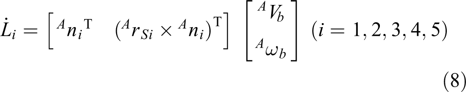
Then, equation (8) can be expressed as


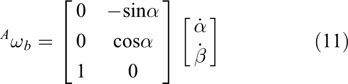
In this parallel mechanism, the angular velocity vector of the moving platform can be written as
The velocity of the moving platform can be obtained by
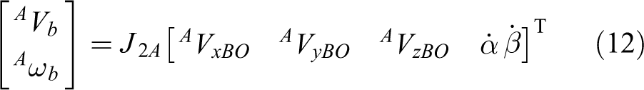
where

Taking equation (12) into equation (9), the velocity variation expressions of five hydraulic cylinders can be expressed as

where
Acceleration variation expressions of five hydraulic cylinders
The acceleration vector of moving platform is

Taking the derivative of equation (8), we can get

where

Taking the derivative of equation (12), we can get

where


Statics model for 4UPS/UP parallel mechanism
The static analysis diagram of 4UPS/UP parallel mechanism is shown in Figure 8.

Static analysis of 4UPS/UP parallel mechanism.
In the moving coordinate system {B}, the static balance equation of parallel mechanism is given as

where Mo
is the external moment of the moving platform,
In the moving coordinate system {B}, the static balance equation matrix is written as

where

The stress of two hydraulic cylinders needs to be regarded as the external load in order to solve the stress of each hydraulic cylinder. Assuming that the stress of
where

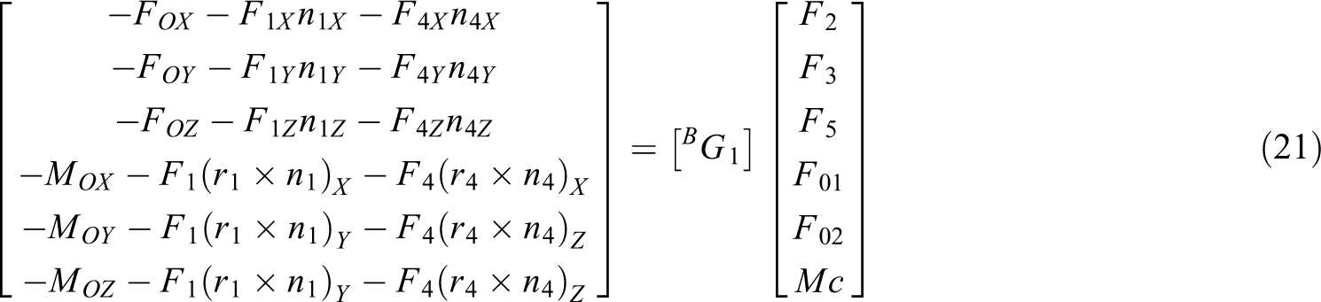
According to equation (21), the stress expressions of the other three hydraulic cylinders, the constraint force and moment of the UP hydraulic cylinder is derived as

where

Calculation examples for 4UPS/UP parallel mechanism
Parameters of parallel mechanism
The distribution of Hooke Joints on the fixed platform is shown Figure 9 and the radius of the fixed platform is assigned as 200 mm. The distribution of Spherical Joints on moving platform is shown in Figure 10 and the radius of the moving platform is assigned as 100 mm.

Distribution of Hooke Joints on fixed platform.

Distribution of Spherical Joints on moving platform.
The coordinates of five Hooke Joints is written as

The coordinates of Spherical Joints and S 5 is

And the gravity of the moving platform is measured as 99.96 N.
Calculation example of kinematics for 4UPS/UP parallel mechanism
The trajectory which the moving platform moves along is given as (unit: mm)

The graphs of length, velocity, and acceleration variation curves obtained by numerical calculation with the MATLAB software are shown in Figure 11. The graphs obtained by virtual simulation with the ADAMS software are shown in Figure 12.
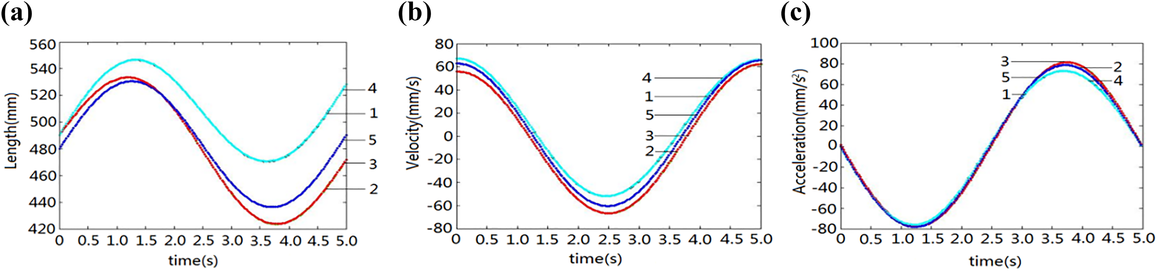
Kinematic curves obtained by numerical calculation: (a) length variation, (b) velocity variation, and (c) acceleration variation.

Kinematic curves obtained by virtual simulation: (a) length variation, (b) velocity variation, and (c) acceleration variation.
Combining Figure 11 with Figure 12, we can conclude the shape of the three curves is basically the same, the trend of the curves is smooth, and presents periodic changes. The maximum error of length variation is 1.13 mm occurred in hydraulic cylinder 2 at the time 3.8 s; the maximum error of velocity variation is 0.04 mm/s occurred in hydraulic cylinder 4 at the time 2.5 s; the maximum error of acceleration variation is 0.38 mm/s2 occurred in hydraulic cylinder 2 at the time 3.7 s. The results obtained by MATLAB and ADAMS are basically consistent, the correctness of the kinematic analysis for 4UPS/UP parallel mechanism is verified.
Calculation example of statics for 4UPS/UP parallel mechanism
There are two conditions in static calculation example, one is the parallel mechanism moves with no load acting on the moving platform, and the external force and moment can be expressed as

The other condition is that the parallel mechanism moves with 50 N loading reverse X axis on the moving platform. The external force and moment in this condition can be expressed as

The trajectory which the moving platform moves along is given as equation (23). The stress of five hydraulic cylinders and the constraint moment of the UP hydraulic cylinder obtained by numerical calculation and by virtual simulation are shown in Figure 13.

Static curves obtained by numerical calculation (left) and by virtual simulation (right): (a) stress with no load, (b) constraint moment with no load, (c) stress with 50 N loading reverse X axis, and (d) constraint moment with 50 N loading reverse X axis.
Contrasting Figure 13, we can find that the stress curve under no-load state is a straight line with very small slope. The value of some straight lines is about 0, and the value of the other straight line is about −50. Under the load of 50 N, the curve is smooth, showing a downward trend from mild to sharp, it can be found that the maximum error of stress is 1.52 N occurred in hydraulic cylinder 2 at the time 5.0 s; the maximum error of constraint moment is
Conclusions
This article presented and verified a creative thinking that parallel mechanism can be applied to the wave energy converter. Design principles are given as a reference for other types of parallel mechanism to be applied to the converter. According to those, a novel wave energy converter with 4UPS/UP parallel mechanism is designed as a special example. Kinematics and static analysis are realized, including establishment and correctness validation of models to verify the feasibility of the wave energy converter. It can provide the theoretical foundation for the experimental prototype and practical application of the converter. In the next step of work, the entity prototype model will be constructed to test in the actual wave condition.
Footnotes
Declaration of conflicting interests
The author(s) declared no potential conflicts of interest with respect to the research, authorship, and/or publication of this article.
Funding
The author(s) disclosed receipt of the following financial support for the research, authorship, and/or publication of this article: This research is supported by the Shandong Key Research and Development Public Welfare Program (2019GGX104011) and the Natural Science Foundation of Shandong Province (ZR2017MEE066).