
Abstract
In this article, a method of multi-connection load compensation and load information calculation for an upper-limb exoskeleton is proposed based on a six-axis force/torque sensor installed between the exoskeleton and the end effector. The proposed load compensation method uses a mounted sensor to measure the force and torque between the exoskeleton and load of different connections and adds a compensator to the controller to compensate the component caused by the load in the human–robot interaction force, so that the human–robot interaction force is only used to operate the exoskeleton. Therefore, the operator can manipulate the exoskeleton with the same interaction force to lift loads of different weights with a passive or fixed connection, and the human–robot interaction force is minimized. Moreover, the proposed load information calculation method can calculate the weight of the load and the position of its center of gravity relative to the exoskeleton and end effector accurately, which is necessary for acquiring the upper-limb exoskeleton center of gravity and stability control of whole-body exoskeleton. In order to verify the effectiveness of the proposed method, we performed load handling and operational stability experiments. The experimental results showed that the proposed method realized the expected function.
Introduction
The power-assistance exoskeleton is an important research area in the upper-limb exoskeleton; thus, various control methods based on human–robot interaction have been proposed. 1,2 Part of the proposed control methods is based on cognitive human–robot interactions (cHRIs), 3 –5 and the other part is based on physical human–robot interactions (pHRIs). 6 –9 The direct force control based on pHRI identifies motion intention by measuring the force and torque between the human and the robot, in order to realize control of the exoskeleton. 2,10 –13 Because there are no constraints between the human arm and the exoskeleton arm, it is easy and fast to put on and take off the robot when the wearer operates the exoskeleton using the controller, and the wearer will not feel uncomfortable. The control signals are provided by the human–robot interaction sensor, so external noise has less influence on the system. The control signals are more stable, repeatable, and reliable than cHRI-based controllers. For industrial applications, the operator needs to wear the exoskeleton for a long time, so the reproducibility, stability, and reliability of the signal measurements are important. 14 Direct force control has advantages in these aspects, so it is more suitable for applications in an industrial environment. 9,15
Direct force control requires the operator to exert an interaction force on the exoskeleton to control its movements. In order for the operator to control the exoskeleton with a small interaction force, it is necessary to add gravity compensation to the controller to compensate for the joint torque caused by gravity. 16,17 At present, many methods for compensating the influence of gravity for the upper-limb exoskeleton have been proposed, such as spring balancing techniques, 18,19 a heuristic method, 20 a passive weight balancing mechanism, 21 minimizing the transmitted joint forces and numerical optimization, 22 rigid-body dynamics, 23,24 and Lagrangian dynamics, 25 so that the operator does not feel the weight of the system during manipulation. However, none of these compensation methods could compensate for load on the end effector. When operating an upper-limb exoskeleton with direct force control, the human–robot interaction force increases with the load. In industrial applications, the load that exoskeleton lifts is heavy, so a load compensation to direct force control is necessary to minimize the human–robot force and reduce the fatigue of the human body after operating for a long time.
There are two kinds of connection between the exoskeleton and the load: passive and the fixed connections. Passive connection is where the load is hinged with the end effector through hooks and so on (without any actuator), and the relative position between the exoskeleton and the load is not fixed when the posture of the upper-limb changes (Figure 1(a)). Since the load center of gravity acts perpendicularly on the fixed point of the end effector, the forces acting on the end effector are only the load gravity and inertia force. These forces change as the weight of the load changes. However, these forces do not change when the load center of gravity and volume change. Fixed connection is when the load and the end effector are fixed by snatches, lifts, and so on, and the relative position between the exoskeleton and the load is fixed when the posture of the upper-limb changes (Figure 1(b)). Since the load center of gravity does not act on a fixed point on the end effector, there is an unknown distance L (L includes the distances in the x, y, and z directions) between the action line of the load center of gravity and the end effector as the posture changes. Therefore, the force acting on the end effector is not only the load gravity and inertia force but also the gravity torque and inertia torque caused by the unknown distance L. These forces and torques change when the weight, center of gravity, and volume of the load change. In conclusion, the changes of the load center of gravity and volume have no effect on a passive connection but have a great impact on a fixed connection.

(a) Upper-limb exoskeleton lifting a load with a passive connection; and (b) upper-limb exoskeleton lifting a load with a fixed connection.
In order to realize load compensation, Lee et al. 14,26 introduced load compensation in the control system to reduce the human–robot interaction force. However, this method only considers passive connection, which cannot be applied to fixed connection. Therefore, we propose a multi-connection load compensation method for an upper-limb exoskeleton based on direct force control by installing a six-axis force/torque sensor between the exoskeleton and the end effector. According to the data measured by the installed sensor, we added a load compensator to the direct force control. Therefore, the proposed method can compensate the component caused by load in the human–robot interaction force and converge the component to 0. Thus, the operator could lift loads of different weights in a passive or fixed connection with the same human–robot interaction force (i.e. augment the muscle strength of the operator).
Moreover, the impact of the load on the overall center of gravity of the upper-limb exoskeleton should not be neglected in the stability control of the exoskeleton. The load information (the weight and position relative to the exoskeleton) directly affects the overall center of gravity of the exoskeleton, which in turn affects the balance stability of the exoskeleton (especially the whole-body exoskeleton) and therefore requires accurate load information for the control system. Based on the measured data of the installed six-axis force/torque sensor, the equilibrium equations of the load can be obtained; then, the numerical solution of the load information can be obtained by the steepest descent method and the Newton method. Therefore, a load information calculation method is proposed. According to the calculated load information method, it is possible to calculate the accurate center of gravity of the upper-limb exoskeleton when lifting loads.
Materials and method
Overview of the exoskeleton system
Exoskeleton system
The exoskeleton used in this article was an upper-limb exoskeleton we designed for lifting loads in industrial applications (Figure 2). Each arm of the exoskeleton had five degrees of freedom (DOFs) (three-DOF shoulder joint and two-DOF elbow joint; Table 1). The system was mounted on a frame that was fixed to the ground and could be worn and operated by a standing operator. The exoskeleton had two points of contact with the operator: hands and waist. The length of the exoskeleton upper arm and forearm referred to human dimensions of Chinese adults, which is the National Standard of the People’s Republic of China. The height of the exoskeleton was adjustable, and the position of the lumbar support could be adjusted back and forth to accommodate operators of different heights and sizes. The control signals of the exoskeleton were provided by the forces measured by the sensor installed in the handle, which was in contact with the operator. The system used a hydraulic station as a power source and hydraulic cylinders as actuators. The hydraulic cylinders were controlled by servo valves to complete the actions of hanging, snatching, lifting, and side lifting on the front and sides of the body. The weight of each part of the exoskeleton is shown in Table 2.

Upper-limb exoskeleton system.
The joint of each arm of the exoskeleton.
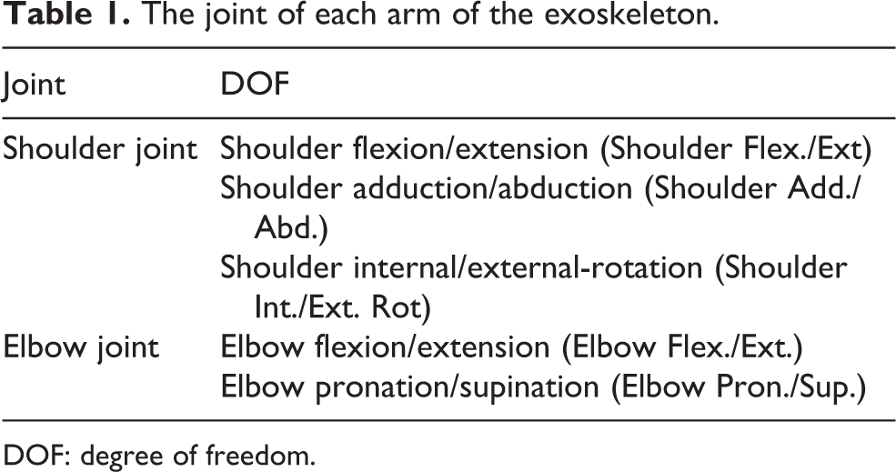
DOF: degree of freedom.
The weight of each part of the exoskeleton.

Exoskeleton modeling
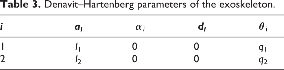
In order for the upper-limb exoskeleton to perform the load lifting action in front of the body to verify the performance of the proposed method, the shoulder joint flexion/extension and elbow joint flexion/extension were controlled. The coordination system and link parameters are shown in Figure 3. Ph is the center of the three-axis force sensor coordination system inside the handle connected to the exoskeleton, and Ps is the center of the six-axis force/torque sensor coordination system installed between the exoskeleton and the end effector to measure the forces and torque of the exoskeleton and end effector. The Denavit–Hartenberg parameters were used for exoskeleton kinematics analysis (Table 3). 27 Therefore, the position of Ph and Ps could be obtained by forward kinematics analysis.

Coordination system and link parameters.
Denavit–Hartenberg parameters of the exoskeleton.
From Figure 3, the dynamic behavior of the exoskeleton robot can be described by Lagrangian dynamics. Equation (1) is the general format of Lagrange’s dynamic model

where
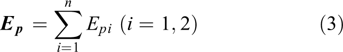
The kinetic energy expression of the exoskeleton dynamics model is shown in equation (2), and the potential energy expression is shown in equation (3).
i
is the link index, mi
is the mass of the exoskeleton link, Pi
is the center of mass, and Ii
is the inertia tensor. In addition, vi
is the linear velocity of the link, and

where
where
Equation (4) is derived from equation (1),

Operating terminal
The handle for operating the exoskeleton is mounted on the front end of forearm of the upper-limb exoskeleton (Figure 4). The operator can operate the exoskeleton to follow human movement through the handle. A three-axis force sensor is mounted in the handle to identify the human motion intention and supply the control signal (Fx , Fy , Fz ) for controller. The coordinate system of the three-axis force sensor is shown in Figure 4.

Handle and coordinate system of the three-axis force sensor.
Load compensation method
Load impact analysis
The joint torque

where
In the direct force control, the joint torque

where
When the exoskeleton is stable with the load, the joint torque provided by the operator through the control system is equal to the joint torque required for the upper-limb exoskeleton and can be expressed as follows

The joint torque provided by the operator through the control system can be described as follows

According to equation (7), comparing equations (5) and (6)
From equations (8) and (9), the human–robot interaction force
When the exoskeleton moves with the load, it is necessary to increase or decrease the human–robot interaction force on the basis of the stable state in order to operate the exoskeleton to follow human movement. That is, the joint torque provided by the operator through the control system is not equal to the joint torque required for the upper-limb exoskeleton and can be expressed as follows

The joint torque provided by the operator through the control system can be described as follows

At this time, the human–robot interaction force

Based on the above analysis, the human–robot interaction force of the direct force control has two functions: the first is to identify the human motion intention and act as a control signal to control the exoskeleton to follow human movement; and the second is to provide the force to balance the torque that the load maps to the joint space. In other words, the human–robot interaction force consists of two components: the component
Compensation analysis
In industrial applications, fixed connection is very common, in order to minimize the human–robot interaction force, load compensation should be considered. When handling load with fixed connection, the position of the center of gravity of the load is different depending on the load volume, shape, and transportation method (Figure 5), which brings great difficulty to the load compensation. Therefore, a load compensation method is proposed based on a six-axis force/torque sensor installed between the exoskeleton and the end effector. The proposed method adds a load compensator to the direct force control according to the force and torque applied to the exoskeleton by the load measured by the six-axis force/torque sensor and compensates the component caused by the load in the human–robot force. The position and coordinate system of the six-axis force/torque sensor is shown in Figure 6.

The position of center of gravity of loads with different transportation methods. (a) Snatching small volume load with one arm, (b) lifting large volume eccentric load with one arm, and (c) lifting heavy load with both arms.

The position and coordinate system of the six-axis force/torque sensor.
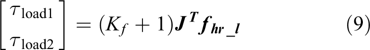
According to the joint torque of the direct force control (equation (6)), the joint torque

where

where
Since the human–robot interaction force consists of two components, according to equation (14), substituting equation (9) in equation (11), the joint torque

According to equations (13) and (15)

Since equation (12)

As can be seen from the above analysis, since the compensator is added to the direct force control, the torque maps to the joint space by the load is compensated by the compensator, so the component
While compensating the load with passive connection,


While compensating the load with fixed connection,


By comparing equations (19) and (21), the passive connection can be regarded as a fixed connection when both
Controller design
The proposed load compensation method needs to be implemented by the controller. According to the above analysis, two kinds of controllers without load compensator and with load compensator for the upper-limb exoskeleton were designed.
(1) Direct force controller:
The direct force control block diagram that provides a control signal by the three-axis force sensor is shown in Figure 7.
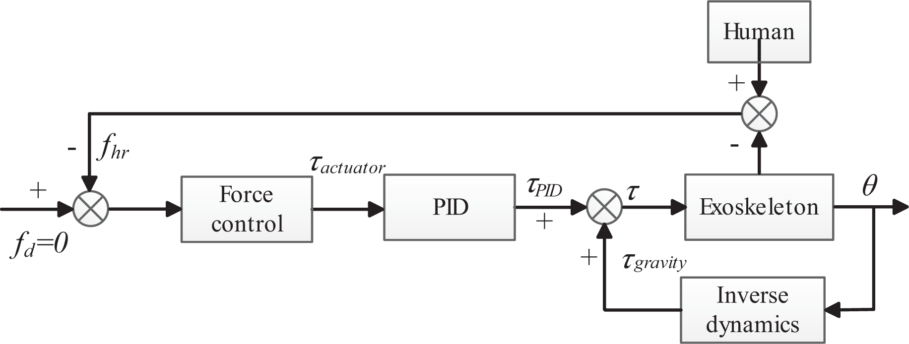
The block diagram of the direct force controller.


Here, Kp , TI , and TD are the proportional gain, integral parameters, and differential parameters of the force controller, respectively. Taking into account the dynamics equations, the torque supplied by actuator can be expressed by equation (26)

(2) Direct force controller with load compensator:
The direct force control block diagram with load compensation is shown in Figure 8. Based on the joint angle
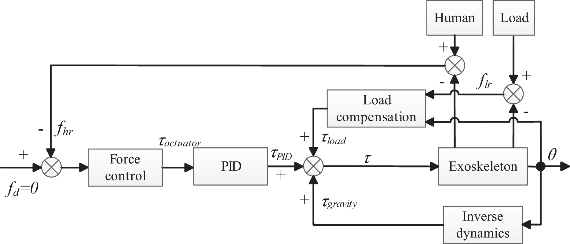
The block diagram of the direct force controller with load compensation.
Based on the above analysis, the torque

Load information calculation method
It is difficult to obtain the load information with fixed connection during operating the upper-limb exoskeleton. However, according to the data measured by the six-axis force/torque sensor, we proposed a load information calculation method, which can obtain the load information accurately and improve the stability of exoskeleton balance.
Load information includes the weight of the load and the position relative to the end effector. The load weight is represented by m and the position of the load relative to the end effector is represented by the position
The interaction force

The angle

The load information to be sought has four parameters, but there are six equilibrium equations. Therefore, compared with the non-load state of the exoskeleton, we calculated the equilibrium equations in the direction corresponding to the two most obvious changing forces and the two most obvious changing torques; that is, four equations were chosen to reduce the error caused by the calculation. Due to the existence of implicit equations, analytical solutions to load information could not be obtained. The steepest descent method was used to iteratively calculate the equations to find the approximate value of the better solution. Then, the Newton method was used to continue the iterative calculation to obtain the solution of the equilibrium equations.
Experiment
To confirm the effectiveness of the proposed method, we validated it on the exoskeleton system. According to the proposed method, we designed lifting experiment, compensation experiment, and load information calculation experiment.
Lifting experiment description
In order to verify the method proposed above, a lifting experiment was performed in the sagittal plane. The experiment was performed by 10 subjects (7 males, height: 172 ± 3 cm; 3 females, height: 168 ± 4 cm) manipulating the exoskeleton from positions 1 to 2 in 5 s, which included the movement of the shoulder and elbow joints (shoulder: 0°–135°, elbow: 0°–95°; Figure 9). All subjects gave their informed consent for inclusion before they participated in the study. The study was conducted in accordance with the Declaration of Helsinki, and the protocol was approved by the Ethics Committee of Beijing Sport University. In order to ensure the same trajectory of the end effector in each experiment, a standard trajectory reference made of a wooden board was placed in parallel with the sagittal plane next to the trajectory, and the subjects were asked to complete several exercises before operation. pe is the position of the end effector, which can be calculated from the angle measured by the encoders attached to the exoskeleton and the kinematics of the exoskeleton. Based on these parameters, the end effector speed can also be solved.

The trajectory of the end effector for the verification of the used controller.
Lifting experiment
The direct force controller controlled the exoskeleton through the human–robot interaction force between the exoskeleton and the operator to control the exoskeleton to follow human motion and perform power assistance. The magnitude and direction of the human–robot force should react to the operator’s motion intention. To verify this, 10 subjects performed a lifting experiment (10 times per subject), and the trajectory of the end effector is shown in Figure 9. The mean value of the end effector position and human–robot interaction force were chosen as the final results.
Compensation experiment
By compensating for the joint torque caused by the load, the component
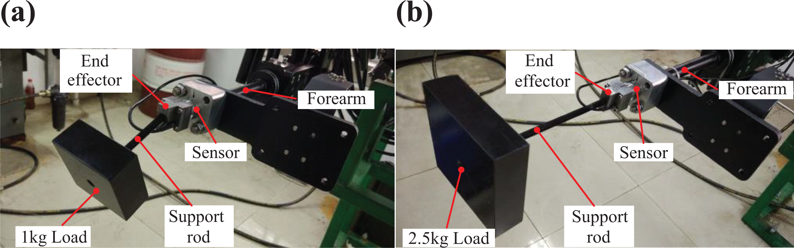
(a) The position of the 1-kg load on the exoskeleton; and (b) the position of the 2.5-kg load on the exoskeleton.
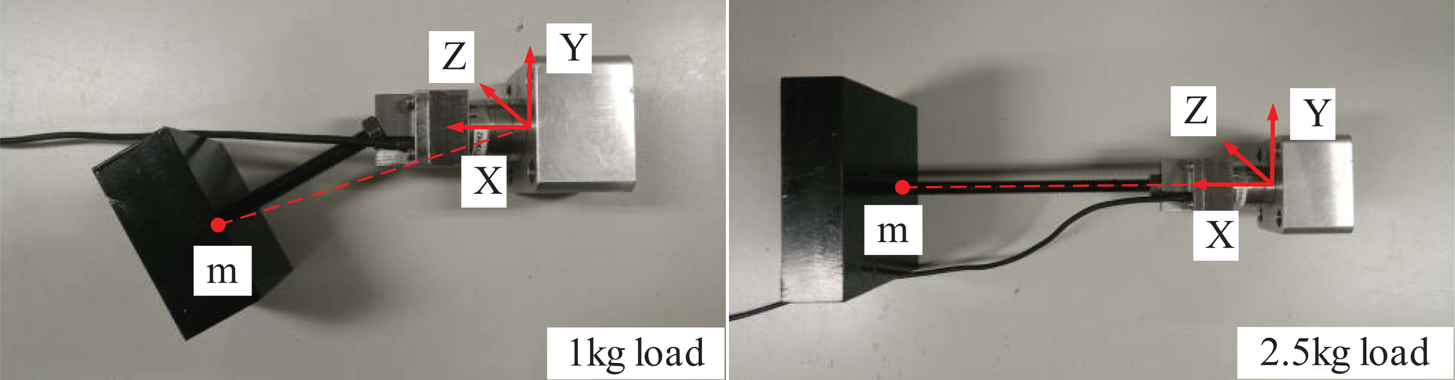
(a) The position of the 1-kg load in the sensor coordination system; and (b) the position of the 2.5-kg load in the sensor coordination system.
A passive connection is a special fixed connection. Therefore, if the experiment was to verify that the load compensation with a fixed connection was valid, then a passive connection would also be feasible. Therefore, in the experiment, only the load lifted with a fixed connection was verified.
Load information calculation experiment
To validate the accuracy of the calculated load information, we used the experimental data of the exoskeleton with load compensation in the load compensation experiment to calculate the load information and compare it with the actual load information. Since the load compensation experiment was completed in the sagittal plane, according to section “Load information calculation experiment,” the equilibrium equation in the direction corresponding to Fx , Fy , Mx , and Mz in equation (29) was selected and iteratively calculated.
Results and discussion
Lifting experiment
According to the final results of the human–robot interaction force, the position and speed of the end effector, the end effector position and human–robot interaction force vector diagram are shown in Figure 12, and the magnitude of the human–robot interaction force vector and the end effector velocity are shown in Figure 13. The coordinate (0, 0) is the position of the shoulder joint (Figure 12). The blue solid line is the motion trajectory of the end effector, the blue point is the position of the end effector at a certain moment, and the red arrow represents the direction of the human–robot interaction force

End-effector position and human–robot interaction force vector.
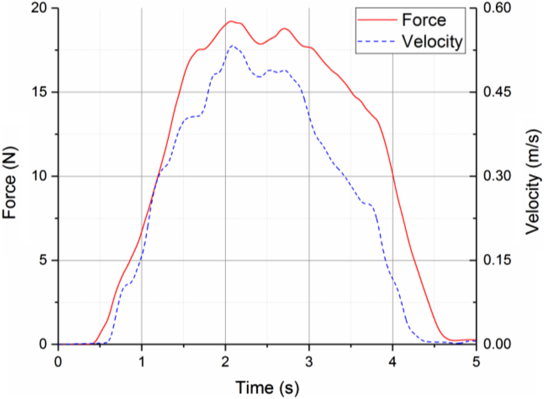
The magnitude of the human–robot interaction force vector and the-end effector velocity.
Compensation experiment
The human–robot interaction force

(a) x-axis position force of

(a) y-axis position force of
As seen in Figures 14 and 15,

where n represents the length of the data for experiment.

Peak and MAE of
From Table 4, as the weight of the load increases from 1 kg to 2.5 kg, the change in the MAE and maximum value of
Statistical results of maximum and MAE of
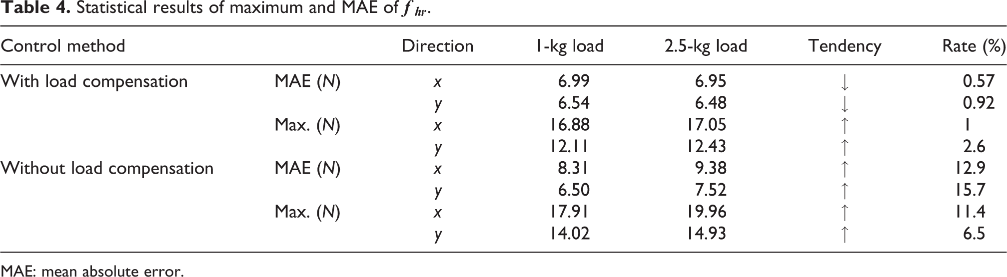
MAE: mean absolute error.
Load information calculation experiment
From section Load information calculation experiment, the load information calculation results are shown in Figures 17 and 18. The thick bars in Figures 17(b) and 18(b) are the average, and the thin lines are the standard deviation of the calculated load information.

(a) Load information of 1 kg; and (b) mean value and standard deviation of load information of 1 kg.
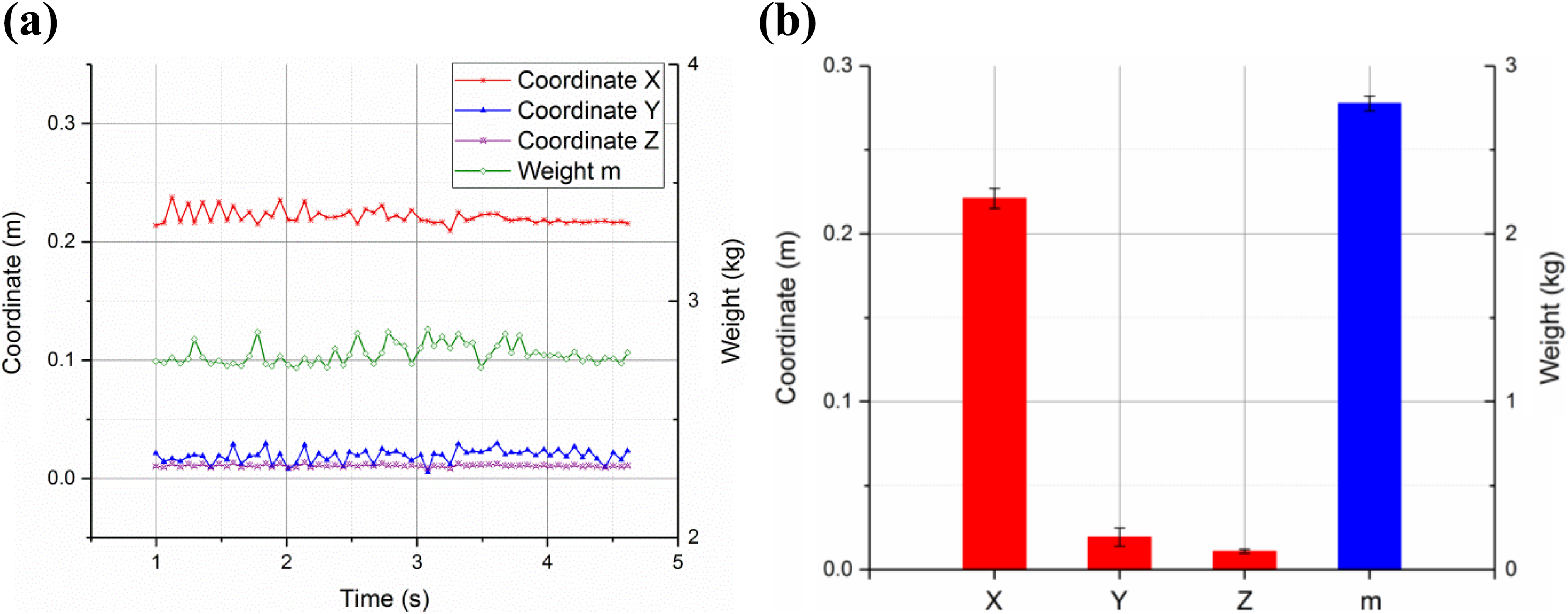
(a) Load information of 2.5 kg; and (b) mean value and standard deviation of load information of 2.5 kg.
In addition to the load, the force and torque measured by the six-axis force/torque sensor included the end effector, the support rod, and the screws (Figure 10). The actual load weight acting on the sensor and the coordinates of the actual load center of gravity are shown in Table 5, which also lists the average value of the load information calculated by iteration.
The actual load information and the calculated average of load information.

It can be seen from Figures 17 and 18 that the two kinds of calculated load information curves fluctuated slightly around their respective mean values, indicating that the calculated load information was relatively stable. It can be seen from Table 5 that the calculated average weight and the actual weight error were not greater than 0.021 kg, and the calculated average coordinate and the actual coordinate error were not greater than 0.019 m, indicating that the calculated average load information was very close to the actual load information. In conclusion, the iteratively calculated load information was in good agreement with the actual load.
Conclusions
In this article, a method of multi-connection load compensation and load information calculation for upper-limb exoskeleton was proposed, and the proposed method was verified by experiments. Conclusions and future work were summarized as follows:
A six-axis force/torque sensor was installed between the exoskeleton and the end effector, and a compensator was added to the controller to compensate the component caused by load in the human–robot interaction force. Hence, the proposed multi-connection load compensation method could be used to reduce the human–robot interaction force based on pHRI. That is, it enabled the operator to manipulate loads of different weights that were lifted with multi-connection using the same human–robot interaction force and realized the effect of augmenting the strength of the operator.
According to the data measured by the six-axis force/torque sensor, the proposed load information calculation method could accurately calculate the information of the load operated with multi-connection, so that an upper-limb exoskeleton could accurately obtain the center of gravity of each part, which is very important for the stability control of a whole-body exoskeleton. The proposed method of load compensation and load information calculation could be considered in industrial applications for an upper-limb exoskeleton or upper-limb systems for a whole-body exoskeleton.
In the future, we will study the cooperative control method of an upper-limb exoskeleton operating loads on both arms and verify the effect and impact of the proposed load information calculation method on whole-body exoskeleton balance control.
Footnotes
Acknowledgment
The authors would like to thank the editor and all anonymous reviewers for their constructive suggestions.
Declaration of conflicting interests
The author(s) declared no potential conflicts of interest with respect to the research, authorship, and/or publication of this article.
Funding
The author(s) disclosed the receipt of the following financial support for the research, authorship, and/or publication of this article: This work is supported by the National key R&D Program of China “The study on Load-bearing and Moving Support Exoskeleton Robot Key Technology and Typical Application” under grant number 2017YFB1300500.