In this article, we present a preliminary analysis of a heavy-lift airship carrying a payload through a cable-driven parallel robot. With unlimited access to isolated locations around the globe, heavy-lift airship enables affordable and safe delivery of heavy cargo thanks to its vertical takeoff and landing capabilities. By considering the airship and the cable-driven parallel robot as a combined system, the kinematic and dynamic models are developed. The choice of the proposed decentralized control structure is justified by the weak coupling of the two subsystems (i.e. airship and cable-driven parallel robot) which makes it possible to control the above two subsystems independently. A robust sliding mode control, capable of auto-piloting and controlling the airship, is developed. Furthermore, an inverse dynamic controller is applied to the cable-driven parallel robot in order to ensure loading and unloading phase. The feature of the proposed control system is that the coupled dynamics between the airship and the cable-driven parallel robot are explicitly incorporated into control system design, without any simplifying assumption. Numerical simulation results are presented and a stability analysis is provided to confirm the accuracy of our derivations.
In the last few years, researchers have become increasingly interested in the development of radically new and sustainable transportation modes for both passengers and cargo. One such new transportation system that uses clean and efficient energy is cargo airships. There are several reasons that such aircraft, called heavy-lift airship, appears attractive for both civil and military heavy-lift application: (i) an airship has the advantage of not requiring large amount of fuel to lift cargo. As a buoyant aircraft, an airship only requires energy for propulsion to move through the air, (ii) its vertical takeoff and landing skills eliminate the need for large teams and maneuver infrastructure, such as fixed-wing aircraft, which still requires airports with an extensive runway, and (iii) buoyant lift does not lead to inherent limitations on payload capacity. Actually, what sustains weight is the physical property of the helium gas. The potential for cargo transport to replace jet aircraft as a lower cost and more sustainable form of air transport is stimulating research and development globally. The use of the lighter-than-air vehicle for cargo transport was resumed in 1996 with the Cargolifter CL 160 design in Germany, an airship that can carry 160 tons. Several other heavy-lift airship projects have followed over the last 20 years like the LMH-1 s, with a load capacity of 20 tons, developed by Lockheed Martin in the United States.
The resurgence of airships has created a need for accurate dynamic models and simulation capabilities to analyze their flight behavior and to design their control systems.1–3 A number of airship dynamic models have been presented in the literature.4–6 A special focus is done on the computation of added masses especially for unconventional airship.7 Many important results have been reported on airship control in the past years. For example, Beji and Abichou8 study the tracking control of a blimp by using a combined integrator backstepping approach and Lyapunov theory. A backstepping controller9 is used to design controllers for airships trajectories tracking.
All the mentioned heavy-lift airships have internal cargo bays to transport their cargo, with the exception of the CL-160 that has a suspended external load frame. This means that airships require a very large operational footprint to load or unload cargo. Hence, the aforementioned heavy-lift airships are ill-suited for logistics operations in a compact area, like those required in over land or sea areas that are beyond the range of the helicopter, limited to handle a suspended payload of up to 20 tons. Typically, these heavy-lift helicopters suffer from slung load swing which can be detrimental to the safety of the assembly. Specifically, dangerous load oscillations often develop as a result of load inertia and movements during flight. Such oscillation makes efficient and accurate transfer of the load difficult. In fact, accidents can be caused by violent suspended load swing.
Limiting the operational footprint of these heavy-lift airships is a key issue. Furthermore, the pendulum-like behavior of suspended load can alter the flight characteristics of the airship, especially when the load is heavy relative to the weight of the airship. In order to overcome the existing difficulties, the airship’s load exchange procedure makes use of a cable-driven parallel manipulator (CDPM), allowing it to load and unload without landing. The airship hovers above the ground and a special loading frame, which is fixed during flight to the keel of the airship, is then handled with cables winches to the ground. The choice of the CDPM for handling a heavy load is justified by its potential properties such as large workspace capability, reconfigurability, and economical structure and maintenance. However, replacing the rigid links by cables introduces many new challenges in the study. Unlike the rigid links,10,11 cables can only apply tensile forces and not compressive forces. Dynamic behavior of the cables is another major challenge in mechanical design and control. In most studies of CDPM, a nonelastic massless cable model is used.12–14 The cables are then considered as straight-line segments. The different works on the control of a CDPM emphasize two main strategies: control in the joint space and control in the operational space.15,16 Other works17 proposed a dual-space adaptive control which is more robust to the variations and uncertainties of certain system parameters. This model allows to calculate anticipation terms that compensate for dynamic forces, both in the operational space and in the joint space.
The focus of this research is to enable the composed system to execute tasks that cannot be accomplished by the robot individually.18 Hence, the airship is used for gross motion of the system, while the CDPM is used for loading and unloading phase. Researchers have only proposed some effective control methods for helicopter carrying a payload using a CDPM.19 In order to control the helicopter and the cable robot independently, a two-time scale control method is proposed where the helicopter motion is considered to be a disturbance in the control design of the cable suspended robot. By selecting appropriate coordinates, the unknown disturbance from the helicopter motion can be modeled as additive terms in the CDPM dynamic model.20,21 Specifically, the slower high-level controller assumes that the reference signals generated by it at any sample time are attained due to the faster action of the lower level faster controller. By operating the cable system in the slow time scale, we can simplify the disturbance term so that its bounds are determined in a state-independent form. However, this approach cannot be used for the heavy-lift airship for the reason that the helicopter has a speed dynamic characteristic compared to the airship with slow dynamic characteristic. Unlike the helicopter,22,23 the airship reacts late and it becomes particularly difficult to control the situation.
Small unmanned aerial vehicles or quad-rotors are also considered for load transportation and deployments. In these results,24 it is assumed that the payload is modeled by a point mass and the effects of the payload are considered as additional force and torque exerted to quad-rotors, instead of considering the dynamic coupling between the payload and the quad-rotor. Recently, a geometric nonlinear control systems is developed by Lee25 for the complete dynamic model of multiple quad-rotor transporting a common payload cooperatively such that the payload exponentially follows a given desired trajectory. The equations of motion are derived according to Lagrange mechanics on the nonlinear configuration manifold in a coordinate-free fashion to avoid singularities and complexities associated with local parameterizations. While these flying robots can maneuver in highly constrained space, they are limited in terms of their payload carrying capacity. In this article, it will be shown how a heavy-lift airship and a CDPM can be effective for aerial physical interaction and manipulation. Concerning this issue, researchers26 focus on cargo airship designs and materials but in order to analyze their flight behavior and to design their control systems, dynamics characteristic studies are still limited.
The contributions of this article are twofold. First, the dynamic model of this multi-body system is determined by considering the coupling effect between the suspended payload and the airship using Kirchoff equation. In this article, the cables are modeled as links connecting the airship to the platform in order to transmit forces from actuated winches fixed underneath the airship to the payload. Second, the control of this complex system consisting of an airship carrying a payload through a CDPM is a major challenge. The reason is that the systems to be controlled are too large and the problems to be solved are too complex. For this purpose, a decentralized control structure is proposed. Indeed, much research has been conducted in this field.27 In our study, we focus on decentralized design for multi-body system which is considered as weakly coupled subsystems. In this case, the controllers behave similarly if the interconnections are sufficiently weak which make it possible to control each subsystem independently.
This article is organized as follows. The concept of the heavy-lift airship is introduced in the second section. The dynamic model is done in the third section. Subsequently, the control is elaborated in the fourth section. To verify the proposed approach, a numerical simulation test result is presented in the fifth section which involves loading phase of cargo airship.
Problem statement and description of the heavy-lift airship
The work of the heavy-lift airship requires the cooperation of the two subsystems (i.e. the airship and the CDPM). Specifically, the airship hovers above the ground and a special loading frame, which is fixed during flight to the keel of the airship, is then rigged with eight cables to the ground. This novel flying robot is composed of four basic components: (i) a moving platform, which is positioned within a workspace to fulfill a specific task, (ii) cables to control and move the platform, (iii) winches which change the cable length, and, finally, (iv) an airship considered as a supporting structure underneath if these winches are fastened.
For loading and unloading, the airship operates as an aerial crane (see Figure 1). Actually, the position and orientation of the suspended platform depend on the cables’ length which can be adjusted by motorized winches fixed on the CDPM base rigidly mounted underneath the airship. In addition to these, the six-dimensional motions of the airship have a direct impact on handling position of the moving suspended platform due to coupling characteristics. In order to provide protection for the safety of heavy-lift airship during loading and unloading phase, it raises an initial idea that the eight motorized winches used to adjust cable length should not only manipulate the suspended platform to track a prescribed desired trajectory but also compensate the six-dimensional motions of the airship. Such a system would eliminate load oscillation and facilitate point-to-point transport without the airship touching the ground and almost independently of local infrastructure.
Loading and unloading of the heavy-lift airship.
Notations: The italic type indicates a scalar quantity, and boldface indicates a matrix or a vector quantity. The transpose operator is . The cross product of two vectors a and b is defined only in three-dimensional space and is denoted by . is a null matrix whose all elements are zero. The kinematic and dynamic analysis of the composed system consisting of the airship and the CDPMs requires a representative parametrization which implies a significant benefit in the motion equations (see Figure 1). In fact, the analysis of the global system motion is made with respect to three reference frames, namely, an earth-fixed frame ; a local frame fixed to the airship , having as origin the inertia center of the airship A; and a platform-fixed reference frame , having as origin the geometric center of the platform P.
Under the established coordinate frames, the generalized coordinates of an airship are expressed by , where we use a parametrization by the Euler angles: yaw, pitch, and roll to describe the airship attitude. The position and orientation of the airship in the inertial reference frame can be described by and , respectively. is the rotation matrix from the local frame to the inertial reference frame
The position vector of the geometric center of the platform P is defined as and with respect to and , respectively, and we express its orientation by the vectors and with regard to and , respectively. is the rotation matrix between the two local frames and
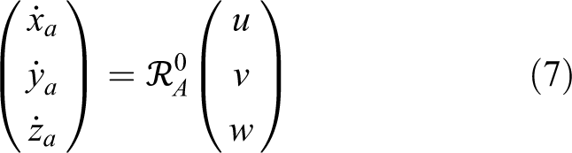
The following shorthand notation for trigonometric function is used: , , and . For this novel flying mechanism, the airship is used as the supporting structure of the CDPM and a six-degree-of-freedom (6-DOF) platform is suspended via cables as transmission element. The general motion of suspended platform with respect to the reference frame can be described by , where and represent, respectively, the linear and angular velocity of the platform expressed in airship body-fixed frame . Let us denote by as the absolute linear velocity of the airship inertia center A with respect to expressed in and is the absolute angular velocity expressed in the airship body-fixed frame . The expression of is given by
where p and denote the relative position and linear velocity of the platform geometric center P expressed in the airship body-fixed frame . The superposed dot, (·), denotes the time derivative relative to a Galilean reference frame, whereas the superposed ring, (°), denotes the time derivative relative to local frame. The time derivative of the above equation with respect to the inertial reference frame gives the linear acceleration defined as follows
The absolute angular velocity of the platform body-fixed frame is equal to the absolute angular velocity of the airship body-fixed frame plus the relative angular velocity of platform body-fixed frame with respect to airship body-fixed frame . Hence, the expression of is given by
The time derivative of the angular velocity with respect to the inertial reference frame gives the angular acceleration defined by
Modeling of the heavy-lift airship
The heavy-lift airship is a multi-body system in which multiple rigid bodies are joined together. During loading and unloading process, the transferred cargo can oscillate due to airship maneuvers. On the other hand, the pendulum-like behavior of suspended load alters the flight characteristics of the airship. To describe the dynamics coupling, the basic motion of one subsystem is regarded as an external disturbance input for the other one. Hence, the dynamic model of this multi-body system composed of the airship and the CDPM can be modeled as an interconnection of lower order subsystems. Specifically, we decompose our system into two isolated subsystems (i.e. the airship and the CDPM). Firstly, the dynamics of the airship is derived and then those of the suspended platform of the CDPM.
Airship kinematic and dynamic model
Kinematic model
In this article, we re-derive the kinematic equations based on Azinheira et al.28 and Fossen.29 Let us denote by as the linear velocity of the airship inertia center A with respect to inertial reference frame and is the linear velocity of the airship inertia center A with respect to inertial reference frame expressed in the body-fixed frame
Let us denote by as the angular velocity with respect to the inertial reference frame expressed in and is the angular velocity with respect to the inertial reference frame expressed in the airship body-fixed frame
where is the transformation matrix from angular velocities to Euler angle rates. The kinematics equations of an airship can be expressed in the following way
Thus, the compact kinematic model of an airship can be written as follows
is the transformation matrix from the airship body-fixed frame to the earth-fixed reference frame.
Dynamic model
By applying the Kirchoff equations, we obtain the motion equation. This method involves two steps. The first one is to formulate the expression of kinetic energy . The second one consists of applying Kirchoff equations as follows
where the force and moment are expressed in the body-fixed frame. The vectors and represent, respectively, the body-fixed linear and angular velocity. We have to note that Kirchoff equations are valid in any reference frame, inertial, and body-fixed as long as independent generalized coordinates are used.
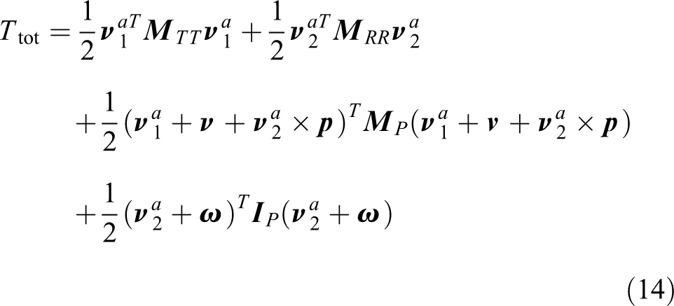
The airship including the suspended CDPM is viewed as an entire system to compute its kinetic energy. For this approach, the nontrivial coupling effects between the dynamics of the airship and the CDPM are explicitly determined by assuming that the nonelastic massless cables are always under tension. The cables are then considered as straight-line segments. Based on these assumptions, the total kinetic energy expressed in local frame is the sum of the suspended platform kinetic energy and the airship kinetic energy defined by
where and are the inertia mass matrix of the airship and platform, respectively, expressed in the local frame . and are the inertia moment matrix of the airship and platform, respectively, expressed in the local frame (see Appendix 1). By substituting the platform absolute linear and angular velocities by the two expressions and , respectively, in the above equation (13), we get
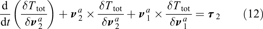
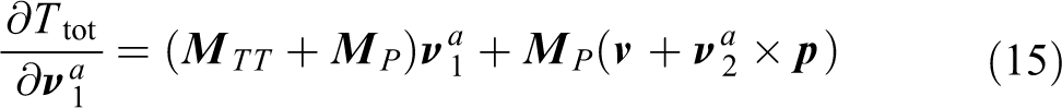
For the airship, the number of independent coordinates is equal to the six-dimensional motion of the airship. The generalized coordinates are chosen as . The partial derivative of the kinetic energy is relative to and
Now taking the time derivative of the two above equations gives
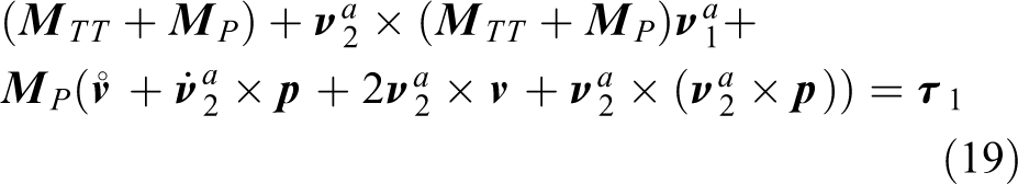
Summing up all the previous terms, we get both force and moment equations
By choosing to substitute the absolute platform velocity in the above kinetic energy expression, the unknown disturbance from the platform motion can be modeled as additive terms in the airship dynamic model. We can combine both force and moment equations as
where
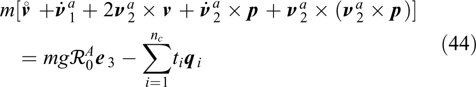
in which is the mass matrix, is the vector of Coriolis and centrifugal terms, and is the added disturbance term due to platform motion. Knowing that , the compact dynamic model of the airship is given by the expression
The resulting wrench applied on the airship is a sum of the force and torque vector generated by the rotors as well as the gravitational and buoyancy force and torque vector . In the following section, we will examine in detail these external forces and moments acting on the heavy-lift airship.
External forces and torques
In our study, we use the characteristics of the airship developed by the French network DIRISOFT. The propulsion of the airship is provided by four electric rotors. Like others flying objects, the airships are subjected to aerodynamic forces. These aerodynamic efforts, represented by the lift and drag of the careen, are function of several parameters such as the Reynolds number, the reference section of the airship, the angle of attack, and the speed of relative wind. The airship is designed with an original shape oriented to a best optimization of the ratio lift upon drag forces. In the first study, we try to evaluate the behavior of the airship in the case of low velocity or while hovering. In these cases, the effect of these forces could be neglected. Indeed, each rotor is attached to an auxiliary frame , where the origin point is the rotor position. Thus, the resultant force and torque can be written as
where is the torque vector due to the force produced by each rotor in the inertia center of the airship A. As previously mentioned, the has four electric engines driving rotors. Each rotor has two parallel contrarotating propellers to avoid any aerodynamic torque. The rotor can swivel in two directions: a rotation of angle around the axis and a rotation of angle around axis. If we suppose that the intensity of the rotor thrust force is having as direction the unitary vector along the axis, then the forces and moments produced by these rotors in the center of inertia A will be defined by
where is the rotation matrix between the frame and the local frame defined as follows
The positions of the rotors in the local reference frame are , , , and . The resultant force and torque vector applied by rotors on the airship are
and
where , , and are component of the vector forces produced by four rotors such that .
An important characteristic of the airships is the buoyancy , where is the volume of the careen, is the density of the air, and g is the gravity acceleration constant. This force represents a natural static lift, corresponding roughly to 1 kg for each of helium involved in the careen. We suppose here that this force is applied in the buoyancy center B different from the gravity center A. In the local frame , the composite effect of gravity and buoyancy is denoted by as follows
where is a unit vector pointing in the direction of gravity, is a rotation matrix, and is the airship mass. The moment due to the weight and buoyancy is
The center of volume B and the center of gravity A lie on the axis of symmetry of the envelope, where .
Modeling of mobile CDPM
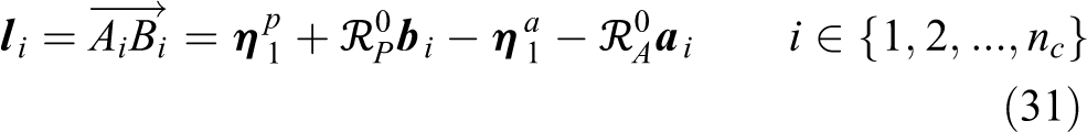
For this novel flying mechanism, the airship is used as the generalized base of the CDPM and a 6-DOF platform is suspended below it via cables as transmission element. Unlike traditional base-fixed CDPM, the exit point of the cable is connected to a mobile pulley mounted on the airship, whereas the other end of the cable is attached to the suspended platform in attachment point and is the ith driving cable connecting these two points. The coordinates of these points are collected, respectively, in the vectors and . is expressed in the local frame fixed to the airship , while is expressed in the local frame attached to the suspended platform . To model this system, we assume that the cables are massless, inextensible, and they are always taut (the cables are always under tension). Here, the platform suspended via cables is taken as the research object. The cable tensions represent the driving force that the motorized winches should output.
Kinematic model
For a CDPM with cables, there are kinematic closures. The components of the vector are expressed in reference frame as follows
To obtain the Jacobian matrix, we only have to derive the cable length with respect to time. We have then
where and are anti-symmetric tensors corresponding to the cross product of the two vectors and , respectively, such that: and . If we generalize for the cables, the matrix writing becomes
Then, the suspended platform twist of the mobile CDPM is defined as follows
in which is the pseudo-inverse of Jacobian matrix J. As it is shown in the above equation, the suspended platform twist can be expressed in two terms. The first one, , is caused by the variation of cable length and the second term, , is the twist due to the motion of the airship. For a conventional CDPM with fixed base, the platform twist is . The forward kinematics (FKs) can be regarded as the dual problem of the inverse kinematics (IKs) analysis. In fact, this model (39) refers to the determination of the suspended platform twist given the linear velocities of the driving cables and the airship twist .
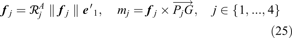
Dynamic model
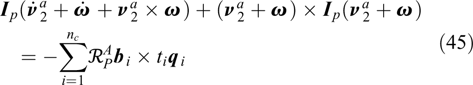
Remember that the overall system consists of a suspended moving platform connected to the airship by means of driving cables. The position and orientation of the platform depend on the cable length which can be adjusted by motorized winch mounted on the airship. We assume that the cable sag is very small and not extensible which means that the cable shape can be seen as a straight line. Thus, the tensions exerted by the cables on the suspended platform at different attachment points , seen as transmission element, have the same direction as the vector . These tensions are collected in a wrench applied at the geometric center P such that the vector groups the cable tensions . The external forces, such as the weight of the platform and its loading, are represented by the vector where is a unit vector pointing in the direction of gravity and m is the platform mass. Using Newton–Euler equations, the dynamic model of the platform is given by the following relation
where and represent the linear and angular acceleration of the suspended platform expressed in , is the inertia moment expressed in the inertial reference frame , and the unit vector along the ith cable. Now, we express the platform motion equations in the airship body-fixed frame as follows
where is the unit vector along the ith cable expressed in and is the inertial matrix of the platform with respect to such that . Then, we substitute similarly the linear and angular acceleration by their expressions and , respectively, in the above equations. Thus, we have
This leads to
By selecting appropriate coordinates, the unknown disturbance from the airship motion can be modeled as additive terms in the dynamics of suspended platform. We can combine both force and moment equations such as
where
The above dynamic model shows explicitly the interaction between suspended platform and movable airship through the expression of the two additive terms and that depend essentially on airship acceleration vector . Knowing that , the compact dynamic model of the suspended platform is given by the following expression
where is the inertia matrix, is the matrix of Coriolis and centrifugal terms, is the disturbance vector due to airship motion, and is the force transmission matrix.
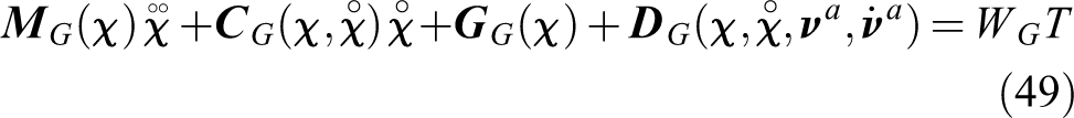
To conclude, our heavy-lift airship is a multi-body system composed of an airship carrying a payload using a CDPM. In our study, cables transmit forces from actuated winches fixed underneath the airship to the payload. Different from the conventional airship or CDPM, the model developed here is intended to include the unknown disturbance from the airship motion in the suspended platform dynamic and vice versa. Gathering both equations (22) and (49), the complete dynamic model is given by
Control design and stability analysis
The heavy-lift airship studied here is composed of a set of rigid solids interconnected by kinematic joints. Due to the inertial coupling between the airship and the load, the load may sway with large amplitudes that may generate dangerous configurations to the system. On the other side, the suspended CDPM suffers from various external disturbances, especially the persistent and unpredictable airship motion. For this purpose, we have applied stabilization control for the airship to attenuate the suspended load swing in order to ensure the system safety and a tracking controller for the cable robot for loading and unloading.
As already mentioned, the dynamic model of the global system is modeled as an interconnection of lower order subsystems (i.e. the airship and the CDPM). The heavy-lift airship is considered as a weakly coupled subsystem. This property has been exploited to design a decentralized controller, which makes it possible to control the airship and the CDPM independently. Specifically, we decompose our system into two isolated subsystems and we elaborate a robust controller of each subsystem. The main goal of the decomposition is the reduction of computational complexity. This control architecture serves as an effective tool to overcome specific difficulties arising in large-scale complex systems such as high dimensionality, information structure constraints, uncertainty, and delays. In this preliminary study, we chose to apply a sliding mode control to stabilize the airship and inverse dynamics with proportional–derivative (PD) controller for tracking trajectory during loading and unloading phase.
Stabilization of the airship
The motion of an airship is usually represented by a set of kinematics and dynamic equations that describe its evolution in a 6-DOF space. Gathering both the dynamic (50) and kinematic (10) model, we get the following two equations
We denote by the velocity state vector, the position state vector, the control vector, and can be considered as the disturbance vector. Our proposed idea consists of developing a stabilization control in such a way that stabilizes the hovering flight of an airship, while being robust against disturbance due to cable tension during loading and unloading process. The desired stabilization corresponds to a control system objective where both the velocity state and the position state are regulated to zero. For designing controller, it is very convenient to use a sliding mode control. First of all, we define a sliding surface and Lyapunov function in the following equation
where is the diagonal matrix such as with . The time derivative of the Lyapunov function is given by
By substituting and from equations (52) and (53) in the previous equation (57)
To ensure the payload asymptotic stability, we must choose a control law that satisfies the condition . Hence, we select the control law as
where K is a positive definite matrix defined as follows
in which
This leads to
Let us note and the terms of the whole mass matrix and the disturbance vector D, respectively. As is known , so we get
Then, it is sufficient to choose
where , therefore,
To avoid chattering, we replace the function by the function given as
δ is a constant boundary layer thickness. Hence, the control law now looks like
The proposed controller (67) consists of three components. Term guarantees the system reaches and remains on the sliding surface. Term is used to compensate. Since this last term has to be computed from actual state vector and changes over time, we suppose that our state vector is measurable.
Referring to LaSalle’s invariance principle, the system is stable. Thus, the motion converges to a maximum invariant set which satisfies . This implies that . The following equation is derived as
By substituting in the previous equation
This leads to
Hence, it is clear that the position can asymptotically converge to zero if we select such that the matrix product satisfies the Hurwitz condition. Therefore, sliding mode control (SMC) provides an effective approach for the control problem of systems with nonlinearities and bounded external disturbances. As already mentioned, the airship has 12 actuators: the four propulsion forces , the four angles of inclination , and the four orientation angles . To control the airship, we have to compute the values of real actuators , and by a control allocation algorithm.30
Tracking controller for loading and unloading
Inverse dynamics with PD controller
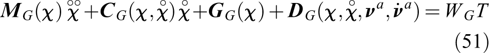
In order to integrate a robust control that can ensure the loading and unloading of the heavy-lift airship, we chose to apply an inverse dynamic controller with PD to our mobile CDPM. To improve the tracking performance of the mobile CDPM, the controller must take into account the dynamic model of the robot in order to compensate the applied forces. This method uses the reference signals and the measured signals of the state from the trajectory generation. Because the technique is model-based, the following motion equation of the suspended platform (51) is needed
Remember that is the mass matrix, is the matrix of Coriolis and centrifugal terms, is the bounded disturbance vector, and is the force transmission matrix. We denote by the Cartesian coordinates of the suspended platform and the vector that groups the cable tensions represents the control vector input. In order to integrate a robust control that can ensure the loading and unloading of the heavy-lift airship along a prescribed desired trajectory , we chose to apply the PD inverse dynamic controller. The control law is given by
where the two positive definite matrices and denote the gain of a corrector PD. As shown in Figure 2, the desired platform trajectory is converted into its associated joint variable using the IK model. The measurements of the joint variables corresponding to cable length are required in the controller feedback loop. In fact, the cable length may be measured by the motor shaft encode, such that , where denotes the initial cables length, r is the shaft radius, and is the motor shaft position. The vector is then converted into operational tracking error using the FK model.
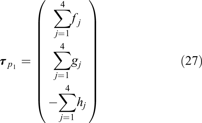
The tracking control of the payload can not only be provided by the adequate choice of the control law but also a cable tension distribution algorithm should be integrated to ensure that the control is capable to keep the CDPM cable tensions always positive.31 In this article, the tension distribution is formulated as a quadratic programming problem as follows
For redundant manipulators, there exist an infinite number of tension distributions . Here, is the pseudo-inverse of the force transmission matrix and is the wrench applied on the geometric center of the platform. All cable tensions are contained between minimal and maximal tension values and . The maximum is notably given by the maximal admissible cable strain whereas is usually set as the lowest acceptable tension with the goal of avoiding slack cables .
Stability analysis
Referring to the control law given by equation (72) and the dynamic model given by equation (71), the closed-loop system will then be
in which . Although the dynamic equations of the global system are nonlinear and complex, they have some known properties which are necessary for the controller synthesis and stability analysis
Property 1. The inertia matrix is symmetric and positive definite.
Property 2. The matrix is skew symmetric.
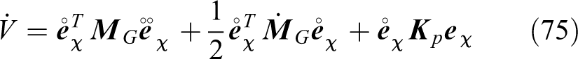
Let V be the Lyapunov function for the closed-loop system
Based on property 1, is positive definite and is chosen to be positive definite. Then, we can conclude that . The time derivative of the Lyapunov function is given by
By substituting from the closed-loop system in the preceding equation
According to property 2, the first term vanishes and therefore
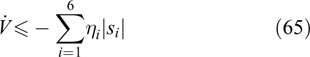
since is chosen to be positive definite. Referring to LaSalle’s invariance principle, the system is stable. Thus, the motion converges to a maximum invariant set which satisfies . This implies that . Substituting these on equation (73), we get . This means that tends to as time t goes to infinity.
Simulation results
One hazardous task in an airship mission is the loading and unloading of the heavy load by means of motorized winches while the airship hovers above the ground. In this section, we test the proposed framework in numerical simulations that have been developed using MATLAB/Simulink. Simulation experiments are conducted on a suspended mobile CDPM prototype having the following characteristics. We use cables to manipulate a suspended platform in the full dimensional task space, thus resulting in two redundant cables that can be used to better distribute the tensions. The suspended platform is a cube with a total mass of kg. Its inertia moment matrix is expressed in the platform body-fixed frame .
Airship
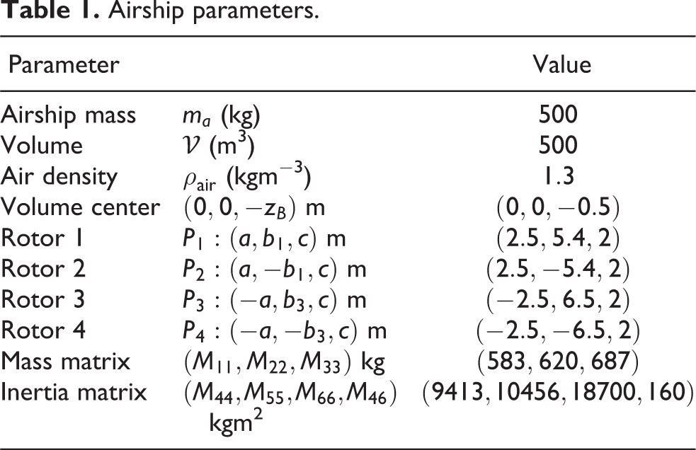
In this first part, a state stabilization problem is simulated on an unconventional airship . The airship parameters are listed in Table 1. The airship initial position and attitude states are m and rad, respectively, whereas the airship initial velocity states are in trim conditions. The controller was designed to hover the airship back to the steady state m from the initial state. It is interesting to note that the airship motion, even though it does not visibly affect payload, it affects the direction of the cable tensions. In fact, by moving the cable exit point , the direction of the cable tensions changes, thus making the suspended platform unstable.
Airship parameters.
Parameter
Value
Airship mass
(kg)
500
Volume
(m3)
500
Air density
(kgm−3)
Volume center
m
Rotor 1
m
Rotor 2
m
Rotor 3
m
Rotor 4
m
Mass matrix
kg
Inertia matrix
kgm2
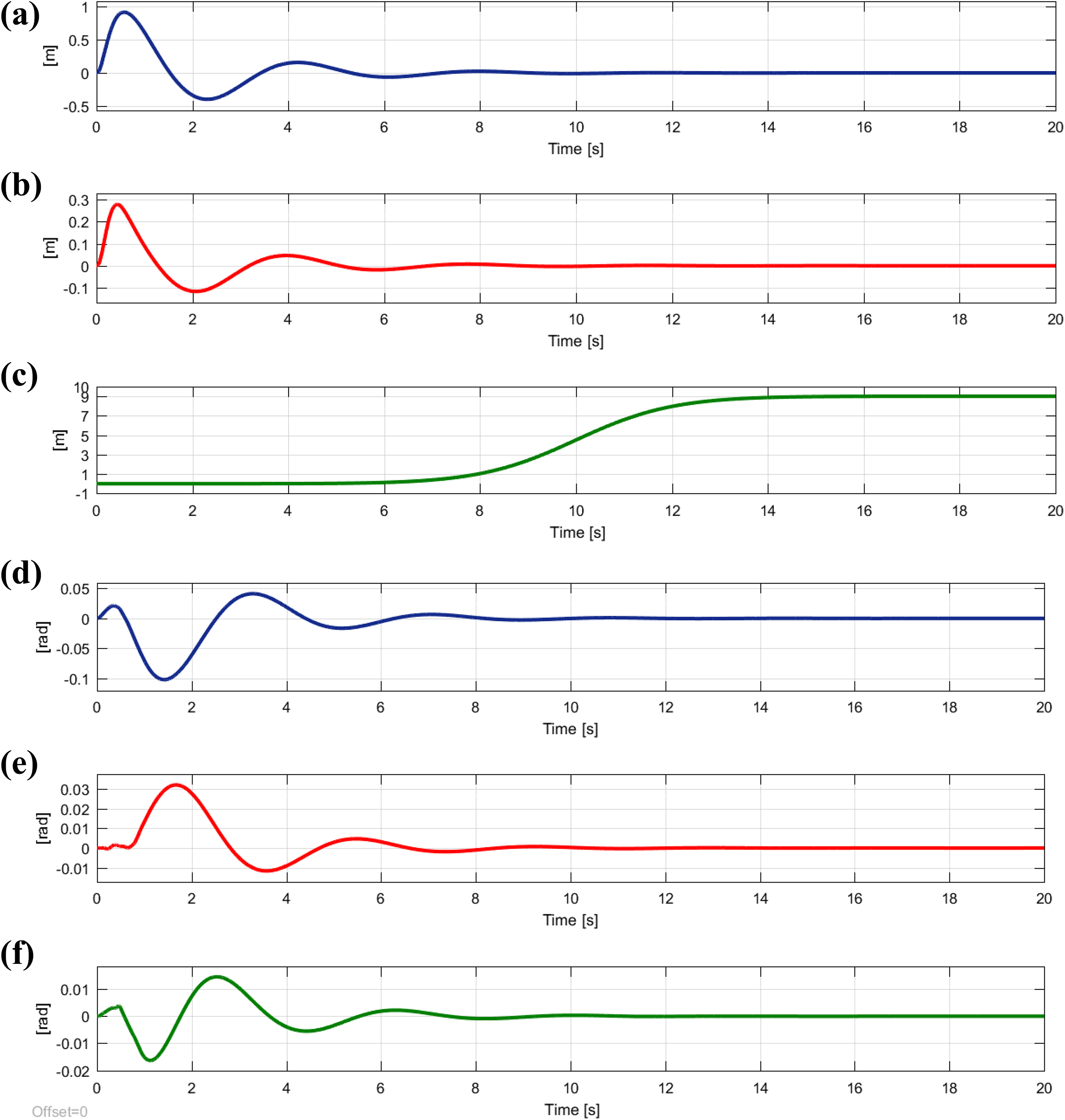
Due to the inertial coupling between the two subsystems (i.e. airship and CDPM), the platform acceleration shown in Figure 3 can destabilize the airship during the loading and unloading process. The developed sliding mode controller has successfully stabilized the airship while being robust against disturbance caused by platform motion. We have to state that the control parameters in our algorithms are all the same in each case (i.e. without and with disturbance). Sliding parameters are chosen as , , and . The resulting simulation is illustrated in Figure 4. In Figure 4, the dashed blue line describes the convergence of airship state vector taking into account the effect of the platform motion, while the red line denotes the results given from the first simulation without disturbance.
Acceleration of the platform considered as disturbance.
Position and orientation of the airship without and with disturbance due to the motion of the suspended platform. (a) Position of the airship along X-axis. (b) Position of the airship along Y-axis. (c) Position of the airship along Z-axis. (d) Attitude of the airship (roll angle). (e) Attitude of the airship (pitch angle). (f) Attitude of the airship (yaw angle).
Mobile cable system
In the second part, we demonstrated through simulation, the influence of airship motion on the moving platform position and attitude firstly situated in a fixed equilibrium point with respect to the platform body-fixed frame such that is a null vector. The airship hovers back from a start point to the end point at steady state, as shown in Figure 4. This movement involves a periodic oscillation in all three translation directions x, y, and z. The roll angle ϕ and the pitch angle θ also oscillate, while the yaw angle ψ remains constant until t = 9 s and then drops down, as shown in Figure 5.
Position and orientation of the platform without control. (a) Position of the platform along X-axis. (b) Position of the platform along Y-axis. (c) Position of the platform along Z-axis. (d) Attitude of the platform (roll angle). (e) Attitude of the platform (pitch angle). (f) Attitude of the platform (yaw angle).
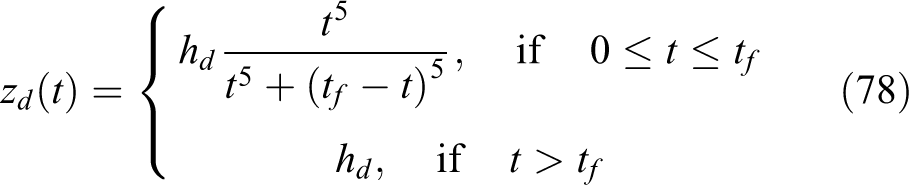
In order to overcome the pendulum behavior which may be inherent and handle the load, an inverse dynamic controller is elaborated. To show the effectiveness of the proposed control algorithm, we suppose that the load is at the origin and has to track the following reference trajectory along the vertical axis to reach a desired position m at a specific time (see Figure 6). It has been generated by a fifth-order polynomial interpolation given by the following expression
Desired trajectory of the suspended platform. (a) Desired acceleration of the platform along Z-axis. (b) Desired velocity of the platform along Z-axis. (c) Desired position of the platform along Z-axis.
We see that our control algorithm for cable robot is able to achieve good tracking performance even with disturbance due to the airship motion. For the fast convergence, the gain matrix is selected as and . As it is shown in Figure 7, position and orientation outputs of the suspended CDPM platform track the desired values very well.
Position and orientation of the platform with inverse dynamic controller. (a) Position of the platform along X-axis. (b) Position of the platform along Y-axis. (c) Position of the platform along Z-axis. (d) Attitude of the platform (roll angle). (e) Attitude of the platform (pitch angle). (f) Attitude of the platform (yaw angle).
In this simulation, we highlight the capability of our inverse dynamic controller not only to manipulate the suspended platform in order to track a prescribed desired trajectory but also to compensate the six-dimensional motions of the airship that ensure safe loading and unloading process.
Conclusion
In this article, we present preliminary analyses of a heavy-lift airship carrying a payload using a CDPM. A special focus is done on the dynamic and control of the heavy-lift airship. Further, a decentralized control architecture is proposed, which makes it possible to control the airship and the CDPM independently. The scenario studied corresponds to the critical case where the airship may be subjected to wind gust during loading and loading phase. By inertial effect, this motion generates the payload swing which can be detrimental to the safety of the assembly. For this purpose, a sliding mode control is developed to ensure asymptotic stability of the airship, while an inverse dynamic controller is proposed for loading and unloading. Besides that, the complete dynamic model of the composed system must be clarified before designing a controller. The dynamic model is derived using Kirchoff equation. Finally, the performance of proposed controller is examined by simulation results and it is evident that the constructed controller ensures the stability of the global system. Our future work will be dedicated to develop the dynamic model of the global system with non-negligible cable mass and elasticity.
Footnotes
Declaration of conflicting interests
The author(s) declared no potential conflicts of interest with respect to the research, authorship, and/or publication of this article.
Funding
The author(s) received no financial support for the research, authorship, and/or publication of this article.
Appendix 1
References
1.
SchmidtDK. Modeling and near-space station keeping control of a large high-altitude airship. J Guid Control Dyn2007; 30(2): 540–547.
2.
ThomassonPG. Equations of motion of a vehicle in a moving fluid. J Aircraft2000; 37(4): 630–639.
3.
HygounencEJungISoueresPet al.The autonomous blimp project of LAAS-CNRS: achievements in flight control and terrain mapping. Int J Rob Res2004; 23(4-5): 473–511.
4.
RubioJDJPieperJMeda-CampaaJAet al.Modelling and regulation of two mechanical systems, IET Science. Meas Sci Technol2018; 12(5): 657–665.
5.
Aguilar-IbañezCSuarez-CastanonMSMendoza-MendozaJet al.Output-feedback stabilization of the PVTOL aircraft system based on an exact differentiator. J Intell Robotic Syst2018; 90(3): 443–453.
6.
RubioJDJ. Robust feedback linearization for nonlinear processes control. ISA Trans2018; 74: 155–164.
7.
AzouzNChaabaniSLerbetJet al.Computation of the added masses of an unconventional airship. J Appl Math2012; 2012: 714627.
8.
BejiLAbichouA. Tracking control of trim trajectories of a blimp for ascent and descent flight manoeuvres. Int J Control2005; 78(10): 706–719.
9.
AzinheiraJRMoutinhoACarneiro De PaivaE. Airship hover stabilization using a backstepping control approach. J Guid Control Dyn2006; 29(4): 903–914.
10.
Ping-LangYChi-ChungL. Dynamic modeling and control of a 3-DOF Cartesian parallel manipulator. Mechatronics2009; 19(3): 390–398.
11.
BingulZKarahanO. Dynamic modeling and simulation of Stewart platform, serial and parallel robot manipulators-kinematics, dynamics, control and optimization. Serial and Parallel Robot Manipulators, 2012.
12.
GouttefardeMGosselinCM. Analysis of the wrench-closure workspace of planar parallel cable-driven mechanisms. IEEE Trans Robot2006; 22(3): 434–445.
13.
GosselinC.GrenierM. On the determination of the force distribution in over constrained cable-driven parallel mechanisms. Meccanica2011; 46(1): 3–15.
14.
SaberOZohoorH. Workspace analysis of a cable-suspended robot with active/passive cables. In: ASME international design engineering technical conferences and computers and information in engineering conference, Oregon, USA, 4–7 August 2013, p. 6.
15.
MerletJP. Kinematics of the wire-driven parallel robot marionet using linear actuators. In: IEEE International conference on robotics and automation, 19–23 May 2008, pp. 3857–3862. Pasadena, CA, USA: IEEE.
16.
LamauryJGouttefardeM. Control of a large redundantly actuated cable-suspended parallel robot. IEEE international conference on robotics and automation, 2013, pp. 4659–4664.
17.
AlpABAgrawalSK. Cable suspended robots: design planning and control. IEEE Inter Con Robot Automat2002; 4: 4275–4280.
18.
LiuXZhaoTSLuoE. Coupling 3-PSR/PSU 5-Axis compensation mechanism for stabilized platform and its analysis. Proc Instit Mech Eng C2013; 227(7): 1619–1629.
19.
OhSRyuJAgrawalSK. Dynamics and control of a helicopter carrying a payload using a cable-suspended robot. ASME J Mech Des2005; 128(5): 1113–1121.
20.
LuYHuB. A unified approach to solving driving forces in spatial parallel manipulators with less than six DOFs. ASME J Mech Des2006; 129(11): 1153–1160.
21.
LuoSChenXFuJ. Stability theorems for the equilibrium state manifold of nonholomic systems in a non-inertial reference frame. Mech Res Commun2012; 28(4): 463–469.
22.
AnanthanSLeishmanJG. Rotorwake aerodynamics in large amplitude maneuvering flight. J Am Helicopter Soc. 2013; 51(3): 225–243.
23.
LopezCAWellsVL. Dynamics and stability of an autorotating rotor/wing unmanned aircraft. J Guid Control Dyn2004; 27(2): 258–270.
LeeT. Geometric control of multiple quadrotor UAVs transporting a cable-suspended rigid body. IEEE conference on decision and control, February, 2015, pp. 1–10. DOI: 10.1109/TCST.2017.2656060.
26.
LiaoLPasternakI. A review of airship structural research and development. Progress in Aerospace Sciences2009; 45: 83–96.
27.
DragoslavDS. Decentralized control of complex systems. Dover Publications, 2011.
28.
AzinheiraJR.de PaivaECBuenoSS. Influence of wind speed on airship dynamics. J Guid Control Dyn2002; 25(6): 1116–1124.
29.
FossenTI. Marine control systems, marine cybernetics AS, 2002.
30.
KhamliaMBennaceurSAzouzNet al.Modeling and actuators design of an unconventional airship. In: ASME international mechanical engineering congress and exposition, 13–19 November 2015, p. 4.
31.
ShiqingFDFranitzaMTorloFet al.Motion control of a tendon-based parallel manipulator using optimal tension distribution. IEEE/ASME Trans Mech2004; 9(3): 561–568.