
Abstract
Bending is an important procedure for processing sheet metals, while it is a key link in the realization of automatic processing of sheet metal. To improve the efficiency and accuracy of bending processing, this article proposed a structure model and a prototype of a six-axis Cartesian coordinate robot for sheet metal bending to replace workers completing automatic bending processes. Based on the analysis of overall structure schemes of the robot, kinematic simulation is conducted by using the automatic dynamic analysis of mechanical system (ADAMS). Furthermore, the dynamic performance of the structural model of the robot for sheet metal bending is analysed and design optimization is performed. A prototype of the robot based on the optimal structural model of six-axis Cartesian coordinate robot for sheet metal bending is made. Finally, under the work conditions, the efficiencies and accuracies of sheet metal bending by a worker and the robot are compared and tested. The structural model of six-axis Cartesian coordinate robot for sheet metal bending presented in this article is found to be applicable to sheet metal bending robot and improves the stability of sheet metal bending machine. The laboratory testing and experimental results verified the feasibility of the proposed robot.
Introduction
Sheet metal processing, as a traditional industry, is common in industrial production and is a labour-intensive, high-risk activity. At present, the bending of sheet metals mainly depends on workers supporting sheet metal by hand, which calls for a high labour-intensity and especially, for heavy gauge sheets, multiple workers are required for safe collaboration. 1 This affects bending accuracy, production efficiency and safety performance. Therefore, this study proposed to complete automatic bending processing by replacing workers with a robot to cooperate with the bending machine, which lays a good foundation for automatic processing of sheet metals.
Robot-assisted bending is being applied to the sheet metal bending gradually. There have been relevant research projects on robot-assisted automatic processing 2 undertaken in the past. Many researchers studied the positioning repeat-ability and payload identification of industrial robots. 3,4 Li and Du modelled processing lines for sheet metals through the simulation software, thus improving production efficiency. 5 Yan et al. developed a robot for sheet metal bending in a five-axis rectangular coordinate system and mainly analysed the flexural rigidity of the main structure. Moreover, improvements thereto were proposed. 6 A secondary positioning of sheet metals based on visual recognition technology was studied and solved for some problems encountered in practical applications. 7 Qian et al. proposed an approach to detect the position of the sheet metal part automatically using image processing. The method can replace the mechanical positioning in the robot-assisted bending and address the time-consuming process. 8 Wang et al. researched the fully automatic bending line integrating a robot for sheet metal bending, a computer numerical control (CNC) bending machine and a loading and unloading material manipulator. 9 The fully automatic bending line has much higher flexibility and processing efficiency in comparison with simple automatic bending elements.
In view of bending sequence planning of sheet metals and process planning of sheet metal forming, Faraz et al. proposed a simulation method for planning the bending sequence of sheet metals to evaluate the influences of process and materials on bending accuracy. 10 Rico et al. proposed a method for solving bending sequence problems in sheet metal manufacturing. 11 Through the method, the parts are divided into those with basic shapes (channel and screw sections) and some sequences related thereto were determined, thus obtaining a complete bending sequence.
For some tube parts widely used in advanced industries, many scholars studied the advanced methods in manufacturing of thin-walled tube bending. Elyasi et al. obtained the smallest bending ratio, and maximum-applicable internal pressure in hydro-rotary draw bending of thin-walled AA8112 alloy tube using necking criterion. 12 To solve the problems such as non-uniform wall thickness, large spring-back, poor fatigue performance, Kong proposed a novel hydro-forming approach to manufacture some thin-walled elbow parts with small bending radius. 13
Phanitwong et al. proposed the model of a Z-shaped bending process of sheet metals and studied elastic recovery characteristics of bent parts upon load release. 14 The changes in sheet metals with process materials and process parameters in spring-back mode were obtained. Yin et al. proposed a control algorithm for robots for sheet metal bending to solve problems, such as program generation, objective calculation and obstacle avoidance. 15 Prasanth and Shunmugam proposed an efficient collision detection algorithm which greatly improved the speed of the process planning for sheet metal bending. 16 By analysing thin sheet bending problems through the finite element method, Abhinav and Annamalai studied the forming characteristics of various metals (such as stainless steel, low-carbon steel and aluminium). 17 Moreover, the normal stress, total deformation, maximum principal stress, equivalent stress and the maximum principal elasticity of parameters were analysed by using ANSYS (R15.0) software. Huh et al. came up with an adaptive method for fast sampling-based motion planning. This method can quickly detect obstacle avoidance for use on robots. 18 To deal with dynamic environmental issues, Lehner et al. proposed a handling method based on an incremental elastic road map. 19 To optimize the global dynamic performance of robotic actuate system from available components, Ge et al. proposed an optimization model whose objective function is composed of matching efficiency and robot natural frequency. 20 Applied an improved teaching-learning-based optimization algorithm, Gao et al. proposed a method of optimal trajectory planning for robotic manipulators that can generate time-optimal trajectories. 21
In the above schemes, multi-joint robots are generally used to cooperate with a bending machine for operation, showing advantages, such as mature technology, easy integration and high versatility. However, there are some shortcomings: (1) Due to the rod length ratio of a robot, sheet metals and joints often interfere with each other in bending heavy gauge sheets. To avoid such interference, it is necessary to dig a pit for the robot or increase the height available for the bending machine. (2) Owing to the universal multi-joint robot not being specific to sheet metal bending, it shows poor dynamic performance in sheet metal bending. To increase the effective range of operation, it generally needs the addition of a seventh axis.
In view of the above problems, according to bending process of sheet metals, the authors investigated the structural design and dynamic response performance of a robot for sheet metal bending based on the design methods and concept of CNC tooling. Meanwhile, the authors proposed a optimizing methods based on ANSYS. A prototype of the robot based on the optimal structural model of six-axis Cartesian coordinate robot for sheet metal bending is made.
This article is structured as follows: in the second section, a structural model of a robot for sheet metal bending is proposed according to the needs of bending process and kinematic simulation analysis is conducted. The third section analyses the dynamic performance of the structure of the robot in sheet metal bending and carries out optimization design. The fourth section presents a prototype of the robot used for sheet metal bending and conducts tests and relevant analysis on its bending processing capabilities. The research is summarized, and possible future research proposed, in the fifth section.
Structural model of the sheet metal bending robot
The process of sheet metal bending is shown in Figure 1. In general, the user coordinate system is set on the knifepoint of the upper die and follows the downward movement of the sliding blocks. The user coordinate system must complete the downward movement with the knifepoint and flip-flop that movement with the sheets. The tool coordinate system set at the flange on the wrist needs to realize motion in both the vertical and horizontal directions and rotation, in three degrees of freedom (DOFs), around the axis parallel to the knife edge of the die. Furthermore, operations, such as capturing, positioning and palletization of workpieces, require a DOF and another DOF is also needed in changing the position of fixtures on the sheets. Therefore, at least five DOFs are needed in robot-assisted automatic bending, that is, the robot requires at least five axes.

Sketch map of following process with bending. 1: Robot, 2: CNC bending machine, 3: fixture, 4: sheet metal, 5: upper die, 6: lower die.
Overall scheme of the sheet metal bending robot
At present, the structural forms of the sheet metal bending robot include three schemes. Scheme 1: universal six-joints robot, which mainly include Abb, Kuka, Fanuc, Yaskawa and so on. Scheme 2: the robot in a rectangular coordinate system, which has typical non-standard structural characteristics and is mainly applied in fields, such as handling, palletization, spraying and welding, so such a robot is a good supplement to universal six-joint robots. Scheme 3: five-axis swing arm robots, which are equivalent to a compromise involving both schemes 1 and 2. Scheme 3 is innovative and designed based on the above two schemes, while it is rarely used at present.
The comparisons of performances of the three schemes in the application in the metal bending industry are shown in Table 1.
Comparison of the three schemes.

The comparisons demonstrate that the Cartesian coordinate robot has obvious advantages in these aspects, such as research and development cycle, manufacturing difficulty, bearing capacity, added value of products, manufacturing cost, processing efficiency and effective operation space. Therefore, the mechanism of the six-axis Cartesian coordinate robot was used in this study. The overall structural model is shown in Figure 2.

Structural model of a robot for sheet metal bending. (a) Structural design scheme 1. (b) Structural design scheme 2. (c) Design scheme of wrist structure. 1: Balance cylinder, 2: beam, 3: Z-axis overhanging beam, 4: column, 5: Y-axis drive screw, 6: X-axis drive parts, 7: Z-axis drive parts, 8: Y-axis overhanging beam, 9: B-axis parts, 10: A-axis parts, 11: C-axis parts.
Design of the structural model of the sheet metal bending robot
Figure 2 shows the three-dimensional (3D) model of the robot for sheet metal bending. Such a robot mainly comprises columns, a beam, a Z-axis overhanging beam, a Y-axis overhanging beam, X-axis drive parts, a Y-axis drive screw, Z-axis drive parts and A-, B- and C-axes parts. Of them, the X-, Y- and Z-axes are three straight axes, while the A-, B- and C-axes denote rotational axes. According to the different requirements for each axis of the robot in the rectangular coordinate system, the overall drive scheme is determined as follows:
X-axis: because the travel range of the axis is long, generally more than 2500 mm, a synchronous belt is used for driving this because for ball-screw drive mode, too long a screw can reduce the natural frequency of vibration of the structure and result in high-speed jitters; as for gear–rack drive mode, although its dynamic response characteristics are good and drive length is not limited, it is expensive. The drive mode based on a synchronous belt at a low cost has no limitations to its drive length (in theory) and moderate dynamic response characteristics, so it is more suitable for X-axis drive.
Y-axis: due to high requirements for positioning accuracy on this axis and sufficient installation space, the ball-screw drive mode is utilized when considering accuracy and economy.
Z-axis: because installation dimensions are limited while a large installation space is required for gear–rack and ball-screw drive modes which are also inconvenient to adjust, the synchronous belt drive mode with compact structure and convenient adjustment is adopted.
A-, B- and C-axes in the end are three rotation axes and the drive modes thereof are the same in joint robots. Therefore, the harmonic drive reducer that has a compact structure and is easily installed is selected. To save installation space, the output end of the motor on the A-axis is connected to the input end of the harmonic drive reducer through the synchronous belt.
Due to heavy parts installed on X-, Y- and Z-axes, the overall rigidity and weight affect the dynamic performance of the whole robot. Therefore, not only is a high rigidity but also a lightweight system is required, which is the key point in the subsequent dynamic analysis and optimization design.
Kinematics simulation based on ADAMS
The following bending process is a typical non-linear motion process and dynamic response characteristics are critical factors restricting the robot. In all parts of the robot for sheet metal bending, dynamic characteristics of the Y- and Z-axes overhanging beams exert the most significant influence on the overall performance of the robot.
In the following, according to the needs of bending processes, the curves of speed and acceleration of the Y-, Z- and A-axes on specific working conditions were obtained through automatic dynamic analysis of mechanical system (ADAMS) simulation, which provided theoretical bases for subsequent dynamic analysis of the structure.
By taking the bending of sheet metal measuring 1250 mm × 1250 mm × 1 mm as an example, kinematic simulation of the following process was conducted.
The main process parameters are listed in Table 2. In Table 2, the feeding speed refers to the movement speed of the upper die during bending of the plates. Acceleration/deceleration time denotes the time required for accelerating the stationary upper die to the required feeding speed. In Figure 3(a), D is the height of the fixture, and L represents the distance from A-axle to the mould centre.
Bending process parameters.

Figure 3(b) demonstrates the kinematic simulation model established using ADAMS. To simplify the model, these parts, such as columns and beams that have a little influence on the kinematic simulation, were ignored. Moreover, the wrist structure was simplified and the effects of the B- and C-axes were neglected.

Simulation model for bending process. (a) Subsequent bending process. (b) Kinematics simulation model based on ADAMS. (c) Simulation on feed speed. 1: Sliding block of bending machine, 2: sheet metal, 3: Z-axis overhanging beam, 4: fixture, 5: lower die of bending machine, 6: A-axis, 7: Z-axis drive parts. ADAMS: automatic dynamic analysis of mechanical system.
The feed speed curve defined by utilizing ADAMS is shown in Figure 3(c). In accordance with the actual working conditions, the acceleration time and the highest speed were set to be 0.2 s and 5 mm/s and the influences of acceleration were ignored. This study only simulated acceleration and uniform-speed processes, while neglected deceleration processes with negligible influences.
The speed curve along the Y-axis is shown in Figure 4(a), showing a typical speed-change process. When the speed begins to increase from motionless to 380 mm/s, the speed decreases to 180 mm/s in the reverse direction and the following process ends. Figure 4(b) presents the acceleration curve along the Y-axis. Acceleration is at its maximum (2300 mm/s2) at the start and then decreases rapidly. Acceleration reduces to −1300 mm/s2 when the feeding acceleration process ends at 0.2 s, then, the acceleration constantly, and slowly, decreases. At 0.4 s, the acceleration slowly increases, and after reaching −300 mm/s2, the bending process ends.
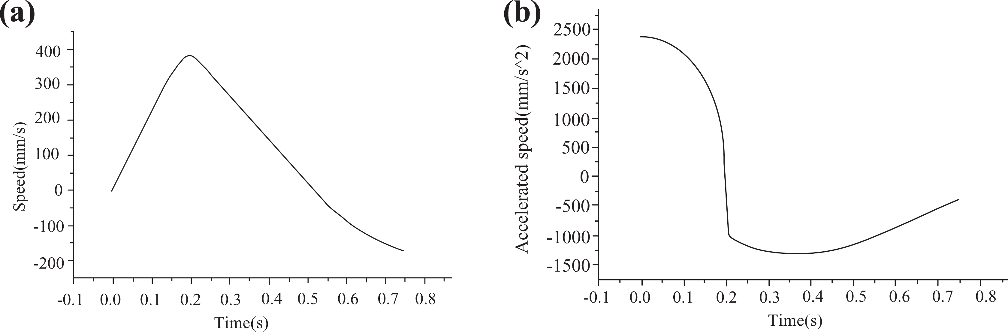
Movement curve of Y-axis. (a) Speed of Y-axis. (b) Acceleration of Y-axis.
The speed curve of the Z-axis is shown in Figure 5(a). The feed begins to accelerate along the Z-axis from motionless and decelerates when the speed reached −960 mm/s; thereafter, it decreased to −660 mm/s in the reverse direction and the process stops. The acceleration curve along the Z-axis is shown in Figure 5(b). In the following bending process, acceleration along the Z-axis shows step changes from −3900 mm/s2 to −5500 mm/s2 in the acceleration stage of the feeding process from 0 to 0.2 s. After ending the acceleration stage of the feed process, the acceleration rapidly increased in steps from −5500 mm/s2 to −800 mm/s2 and then slowly rose to 800 mm/s2, thus ending the process. When the acceleration of the feed ends at about 0.2 s, the rate of change of acceleration was high and this had a significant effect on the system.

Movement curve of Z-axis. (a) Speed of Z-axis. (b) Acceleration of Z-axis.
Figure 6(a) shows the speed curve around the A-axis. The feed begins to accelerate from motionless and when it reaches −75°/s, it begins to decrease to −55°/s, so the following process ends. Figure 6(b) shows the acceleration and speed around the A-axis. The change matches the step change along the Z-axis. In the feeding acceleration stage from 0 to 0.2 s, the acceleration varies from −350°/s to −420°/s. After ending the acceleration stage of feeding, the acceleration quickly changed, in a step-wise manner, from −420°/s to −30°/s and then slowly rose to 8°/s, so ending the process.

Movement curve of A-axis. (a) Speed of A-axis. (b) Acceleration of A-axis.
The obtained speed and acceleration curves for the Y-, Z- and A-axes provide theoretical bases for subsequent analysis and optimization design of the dynamic performance of the robot.
Optimization design of the sheet metal bending robot
The robot for sheet metal bending bore the effects of inertial loads of its own moving parts, fixtures and work pieces, so the dynamic response of the structure was complex. Particularly, when the robot and the bending machine were compared in the following process with bending, jitters and deformation caused by its innate dynamic characteristics, these affected the response speed and positioning accuracy of the robot. Therefore, this study conducted analysis and optimization design of the dynamic characteristics of the robot for sheet metal bending, thus improving the response speed and accuracy of the whole robot.
Main performance index of the robot
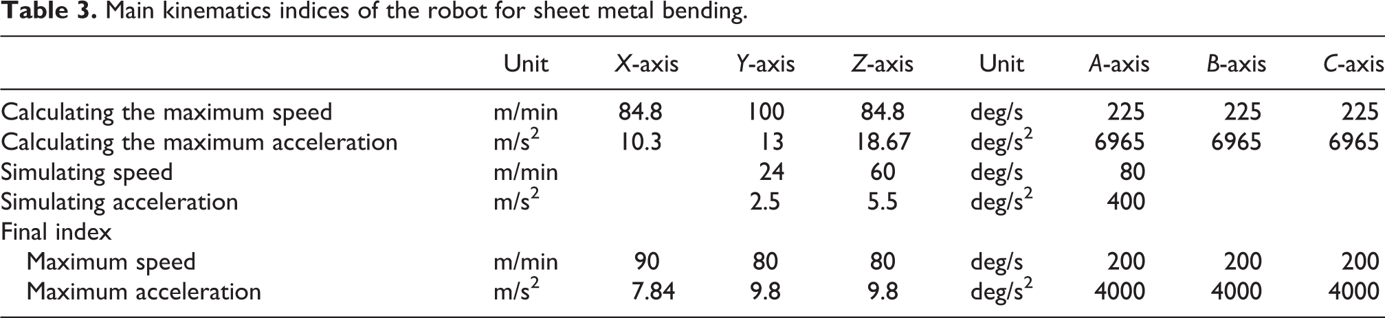
Based on ADAMS kinematics simulation results, the performance indices of the robot in actual working conditions were determined by combining data with the actual working conditions and comprehensively considering multiple factors, such as service life of drive parts, as shown in Table 3.
Main kinematics indices of the robot for sheet metal bending.
The Y- and Z-axes overhanging beams, as main parts, bore their own inertial loads as well as fixture and sheet metal loads. Whether, or not, the structure is reasonably designed directly affects the response speed and trajectory accuracy of the whole robot. Therefore, it is necessary to set it properly, reduce the weight of the structure and improve the overall mechanical performance.
The Y-axis overhanging beam was L-shaped. To reduce welding deformation, the beam (mass, 120 kg) was welded with rectangular steel tubes measuring 400 mm × 350 mm × 8 mm. The Z-axis overhanging beam (mass, 150 kg) was I-shaped and was welded with the steel bar measuring 400 mm × 300 mm × 8 mm.
Static analysis
To determine whether, or not, key parts, such as the Y- and Z-axex overhanging beams had low rigidity in local areas, static analysis was conducted for the whole robot. To obtain higher analysis accuracy and operational efficiency, some detailed characteristics were neglected and abstract mass elements were used to replace fixtures and drive parts set on the X-, Y- and Z-axes. Moreover, motion pairs between the guide rail and ram were bonded by using the co-node method. To simplify the model, this research only studied a specific pose where the X-axis was in the middle and the Y- and Z-axes were in their maximum extension positions.
The finite element model of the robot for sheet metal bending established through ANSYS was divided into 189,402 Solid186 elements and contained 249,804 nodes and 22 Mass21 mass elements (Figure 7). When structural deformation under the effects of inertial loads in the Y-direction was calculated, inertial loads of 1 g in the Y-direction were applied to the Y-axis overhanging beam, fixtures, metal sheet and Y-axis drive parts. In the calculation of structural deformation under inertial loads in the Z-direction, 1 g inertial loads in the Z-direction were applied to the Z- and Y-axes overhanging beams, fixtures, metal sheet and Y-axis drive parts, and displacement constraints in the X-, Y- and Z-directions were imposed on foundation bolts.

Mesh model of the robot in ANSYS.
Under the effects of inertial loads in the Y-direction, the deformation nephogram of the whole robot is as shown in Figure 8(a). Columns and the beam deformed slightly, while large bending and elastic deformation was found in the Z-axis overhanging beam. The Y-axis overhanging beam exhibited small elastic deformation while it underwent large displacement with bending deformation of the Z-axis overhanging beam. Deformation displacement of the wrist was maximized reaching 1.07 mm and such deformation exerted adverse effects on following accuracy with bending and positioning accuracy of sheets also impaired. Figure 8(b) shows the nephogram of the whole robot under the effects of inertial loads in the Z-direction. Columns and beam had small deformation, while great bending and elastic deformation was shown on Y- and Z-axes overhanging beams. Moreover, the maximum deformation was found at the wrist and reached 1.34 mm. Deformation of the wrist in the Y- and Z-directions impaired following accuracy with bending and positioning accuracy of the sheets also affected, so the design scheme needed to be optimized.
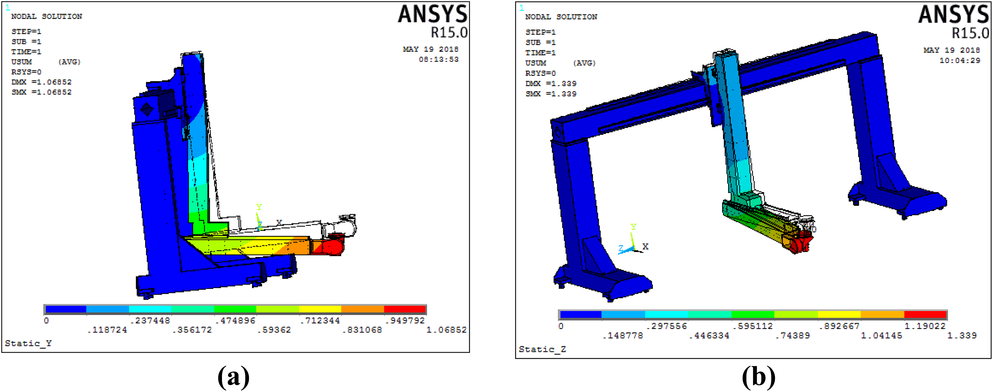
Deformation of the robot under the effects of inertial load. (a) Deformation of the robot in the Y-direction. (b) Deformation of the robot in the Z-direction.
Modal analysis of the sheet metal bending robot
When parts accelerated and decelerated frequently, structural parts underwent elastic deformation under the effects of inertial loads. After acceleration and deceleration processes ended, inertial loads disappeared instantaneously and structural parts vibrated at their natural frequency. In the operation of the robot for sheet metal bending, because there was no stable harmonic excitation load, it was less likely to generate resonance. The purpose of modal analysis is (1) when the natural frequency of vibration of the structure is close to the adjusting frequency of the position loop, speed loop and current loop of the servo system, it is easy to induce vibration in the structure and buzzing of the motor, thus greatly affecting the servo response characteristics of the system. (2) Through the analysis of vibration modes, the position lacking most structural rigidity can be determined for optimization design, so as to avoid the influence of excessive elastic deformation and its effect on movement accuracy of the robot.
In the finite element modelling, the following four assumptions are made: In general, damping characteristics slightly affect vibration modes and natural frequency, so the influences of damping characteristics are neglected. The non-linear factors are subjected to linear processing and co-nodes of motion pairs on the X-, Y- and Z-axes are fixed. The fixture and the drive parts on the X-, Y- and Z-axes influence the modal analysis results. To simplify the model, Mass21 mass elements are used for replacing these parts. Owing to each axis being located in different positions, the modal characteristics of the robot are significantly different. Considering extreme working conditions, the condition whereby the X-axis is in its middle position and the Y- and Z-axes are in their maximum extension positions is modelled.
By modelling the whole robot with ANSYS, the first four-order modes of vibration of the structure are obtained by using the Lanczos method and the results are as follows:
The first-order mode is shown in Figure 9(a): its frequency is 13.22 Hz and vibration mode is a local bending vibration of the L-shaped beam formed by the Y- and Z-axes overhanging beams in the YOZ-plane. Moreover, columns and beam basically remain stationary and this affects the trajectory accuracy of the robot, so optimization design needs to be conducted on this first-order mode.

Modal analysis results. (a) First-order mode. (b) Second-order mode. (c) Third-order mode. (d) Fourth-order mode.
Figure 9(b) shows the second-order mode at 15.05 Hz. The mode appears as the local swinging of the L-shaped beam formed by the Y- and Z-axes overhanging beams in the XOY-plane, and beam and columns are near-motionless, which affects the trajectory accuracy of the robot, so optimization design is necessary.
The third-order mode is shown in Figure 9(c), at 20.5 Hz: this mode demonstrates the overall vibration of the framework formed by the columns, beam and Y- and Z-axes overhanging beams along the Y-axis. This mode affects the trajectory accuracy of the robot, so optimization design is needed.
In the fourth-order mode, as presented in Figure 9(d), the frequency is 26.34 Hz and the vibration modes are shown as an overall vibration of the framework formed by the columns, beam and Y- and Z-axes overhanging beams and torsional vibration around the axis parallel to the Z-axis passing through the centre of the Y-axis overhanging beam. This mode significantly influences trajectory accuracy, so it is necessary to carry out optimization design.
Optimization design
Optimization design of the structure
The structural characteristics of the Y- and Z-axes overhanging beams affected the dynamic performance of the whole robot. In the primary scheme mainly considering the requirements of bending process, section bars were used for welding with a minimum amount of welding, however, owing to there being no partitions for support within the cavity, the rigidity was poor, which influenced the dynamic performance of the whole robot. Therefore, according to the finite element analysis results, this study conducted optimization design of the Y- and Z-axes overhanging beams. The specific scheme is as follows:
The optimized structure of the Y-axis overhanging beam is shown in Figure 10 and the specific measures are presented as follows: The rectangular cavity was welded with steel plates, and rectangular partitions were placed within the cavity. To reduce the overall weight, square holes were formed in the centre of each partition (thickness, 4 mm) and at spacing ranging from 250 mm to 300 mm. The edges of the partitions were welded discontinuously on the cavity wall, giving a weld length of 30 mm and a spacing of 50 mm. U-shaped reinforcing ribs (thickness, 4 mm) were welded on side walls in the rectangular cavity, so as to increase the overall rigidity and stability. The cavity structure changed from the original structure welded with rectangular steel tubes measuring 400 mm × 300 mm × 8 mm into the structure welded with metal sheets measuring 300 mm × 200 mm × 4 mm. After optimization and improvement, the overall mass was decreased from 120 kg to 80 kg, a decrease of 40%, while both the static and dynamic rigidity increased.

Optimized structure of the Y-axis overhanging beam.
The optimized structure of the Z-axis overhanging beam is shown in Figure 11, specific measurements include: In the rectangular cavity, partitions for support were added. To reduce the weight, square holes were cut in the centre of the partitions (thickness, 4 mm) at spacing of between 250 mm and 300 mm. The four edges of the partitions were discontinuously welded to the cavity wall with a weld length of 30 mm and a spacing of 50 mm. For the rectangular cavity, the original structure welded with rectangular steel tubes measuring 400 mm × 350 mm × 8 mm was improved compared to the structure welded with metal sheets measuring 300 mm × 250 mm × 4 mm. After optimization, the overall mass was decreased from 150 kg to 90 kg, a reduction of 33.3% while both the static and dynamic rigidity increased.
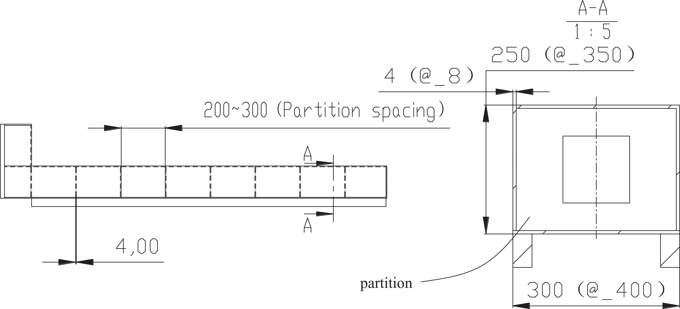
Optimized structure of the Z-axis overhanging beam.
Analysis of mechanical characteristics of the optimized robot
The following section shows the finite element static analysis and modal analysis on the optimized structure and the optimization results are verified.
Static analysis
The nephogram of the whole robot under inertial loads of 1 g acceleration in the Y-direction is shown in Figure 12(a). The maximum deformation is 0.69 mm, which was decreased by 0.38 mm compared with the 1.07 mm before optimization (a decrease of 36%). Figure 12(b) shows the nephogram of the whole robot under the effects of inertial loads in the Z-direction. The maximum deformation fell, from 1.34 mm before optimization, to 0.79 mm, a decrease of 0.55 mm (41%).
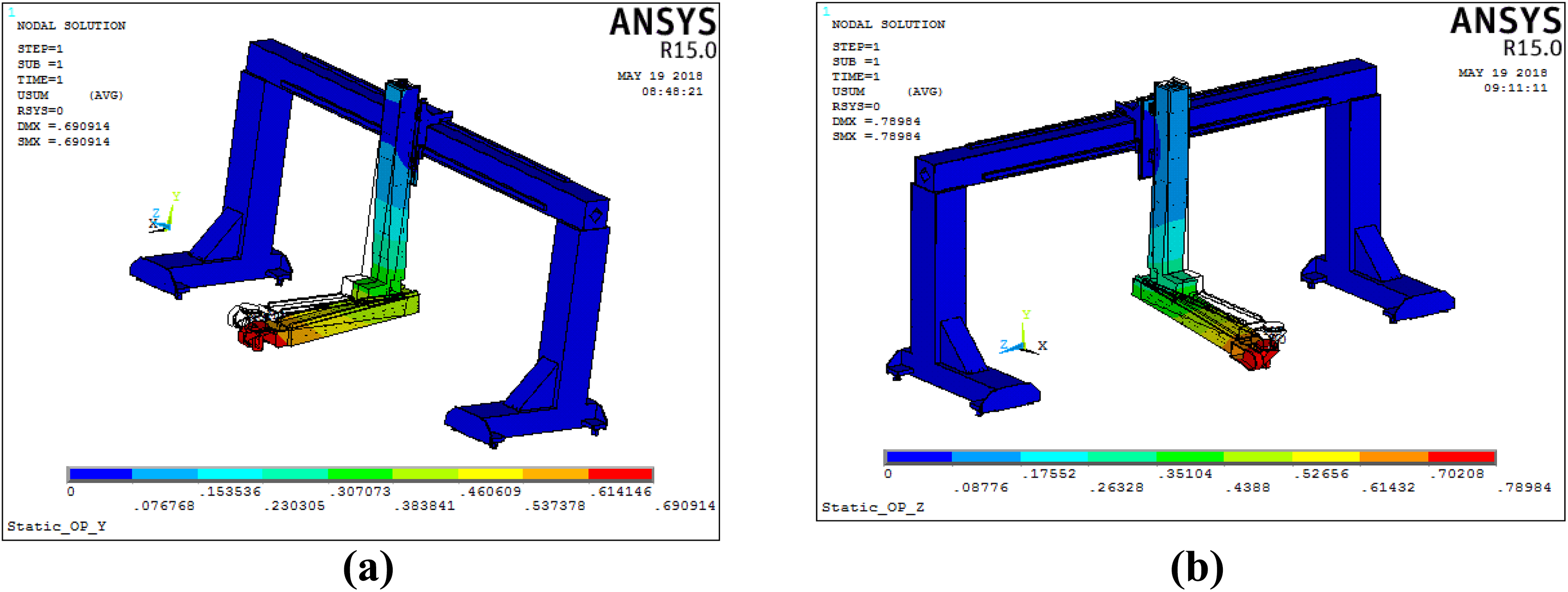
Nephograms of deformation under the effects of inertial loads after optimization. (a) Nephogram of deformation of Y-axis overhanging beam in the Y-direction. (b) Nephogram of deformation of Z-axis overhanging beam in the Z-direction.
Modal analysis
The results relating first-order mode are shown in Figure 13(a): the frequency is 16.7 Hz, which increases by 3.5 Hz (27%) compared with 13.2 Hz before optimization.

Modal analysis results after optimization design. (a) The first-order mode. (b) The second-order mode. (c) The third-order mode. (d) The fourth-order mode.
The results about second-order modal are shown in Figure 13(b). The frequency increases from 15.4 Hz before optimization to 19.2 Hz, an increase of 4.16 Hz (28%).
The results relating to the third-order mode are shown in Figure 13(c). The frequency increased from 20.5 Hz before optimization to 32.7 Hz, an increase of 12.2 Hz (60%).
The results relating to the fourth-order mode are shown in Figure 12(d). The frequency is 38.8 Hz, an increase of 12.5 Hz (47%) in comparison with 26.3 Hz before optimization. The modes of vibration of the first four order modes are the same as those in the primary design schemes, reaching the expected effects.
The comparisons of results of the structures before, and after, optimization design are summarized in Table 4. After optimization, although the welding process for the structure is somewhat complicated, the mass of the structure was significantly reduced and static and dynamic rigidity thereof were improved.
Comparisons of dynamic performance before, and after, optimization design.

Testing experiment for the prototype of bending robot
Trial-manufacture of the prototype based on modular design
Based on the structural model of the robot for sheet metal bending presented in the second section, a prototype of the six-axis robot for sheet metal bending was designed (Figure 14). The robot mainly comprised columns, a beam, Y- and Z-axes overhanging beams, a wrist, a control cabinet and a demonstrator. The prototype adopted the modular design concept and key parts, like columns in both sides of portal frame, beam, Y- and Z-axes overhanging beams, a wrist and drive parts of each axis were designed as independent sub-modules. Meanwhile, the standard mechanical interfaces were pre-set in each sub-module, facilitating installation and positioning.

Prototype of the robot for sheet metal bending. 1: Beam, 2: HD0412 CNC bending machine, 3: wrist, 4: Z-axis overhanging beam, 5: Y-axis overhanging beam, 6: secondary positioning station, 7: work blank laying table, 8: column, 9: finished material table.
A synchronous belt was used for driving along the X-axis and these parts, such as a drive motor, a planetary reducer, a synchronous belt, an X-axis slide carriage and a linear guide, were incorporated (Figure 15(a)). Of them, the X-axis slide carriage was non-rigidly connected to the beam through the linear guide to form motion pairs in the X-direction and the planetary reducer was set on the X-axis slide carriage. The input shaft of the reducer was connected to the output shaft of the motor. Moreover, the synchronous pulley was installed on the output shaft and meshed with the synchronous belt.

Inner structure of the robot for sheet metal bending. (a) Structure of X-axis drive parts. (b) Structure of Y-axis drive parts. (c) Structure of Z-axis drive parts. (d) Wrist structure. 1: synchronous belt, 2: liner guide, 3: X-axis slide carriage, 4: drive motor, 5: reducer, 6: synchronous pulley, 7: drive motor (inner), 8: synchronous pulley and belt, 9: liner guide, 10: ball screw, 11: Z-axis slide carriage, 12: synchronous pulley, 13: reducer, 14: drive motor, 15: liner guide 16: Synchronous belt, 17: B-axis, 18: C-axis, 19: A-axis (inside).
A ball-screw drive structure was used on the Y-axis and mainly comprised a motor (enclosed in the Y-axis overhanging beam), a synchronous belt, a linear guide and a ball screw (Figure 15(b)). The motor drove the ball-screw for rotation through the synchronous belt and the screw was fixed and installed on the Y-axis overhanging beam through bearing pedestals on both sides. The nut of the screw was fixed and installed on the lower part of the Z-axis overhanging beam, and the Y-axis overhanging beam was non-rigidly connected to the lower part of the Z-axis overhanging beam through the linear guide, to form motion pairs moving in the Y-direction.
The Z-axis was driven by using the synchronous belt, mainly consisting of a drive motor, a planetary reducer, a synchronous pulley, a synchronous belt, an X-axis slide carriage and a linear guide (Figure 15(c)). Of them, the Z-axis overhanging beam was non-rigidly connected to the X-axis slide carriage through the linear guide, forming a motion pair in the Z-direction. A planetary reducer was installed on the X-axis slide carriage and the input shaft of the reducer was connected to the output shaft of the drive motor. Furthermore, a synchronous pulley was installed on the output shaft and meshed with the synchronous belt.
The wrist structure is shown in Figure 15(d): axles of the A-, B- and C-rotational axes intersected at one point. To achieve the goal of lightweight design, aluminium alloy was used for casting the structure.
Bending test of the robot
The bending test set-up is shown in Figure 16(a). By using the robot for sheet metal bending to cooperate with the HB0412 CNC bending machine, the elements for automatic bending processing were formed. The Q235A sheets (thickness, 1 mm, dimensions 350 mm × 200 mm) were used for bending through 90°. The width of die slot was 8 mm and four bending procedures were needed. In view of the above bending samples (Figure 16(b)), a worker and a robot separately bent 10 samples and the time taken was measured in hours. Afterwards, we compared the processing efficiency and accuracy of the worker and the robot under the same conditions. Comparison of bending efficiency: based on the processing efficiency for a single sheet, the time taken for manual bending was about 30 s, while the robot needed 48 s; however, the worker could not work continuously for a long time. According to actual comparisons, the worker bent 56 workpieces in an hour, while the robot bent 75 workpieces, so the efficiency improved by 34% when using a robot. The longer the working time was, the more superior the robot. Comparison of processing accuracy (dimensional accuracy and angular accuracy). Manual bending generally adopted a non-feedback mode and showed low accuracy; while for the robot, the displacement sensor was used for real-time feedback of feeding position of sheets, demonstrating high positioning accuracy and stability. In the test, the GT-H10 displacement sensor was used and the accuracy reached 8 µm. By considering factors, such as sensor calibration, positioning accuracy of the robot and assembly accuracy of the bending machine, the positioning accuracy of the sheets was generally controlled to within ±0.02 mm, which was much higher than the manual positioning accuracy. In general, angular accuracy was determined by the accuracy of the bending machine itself, and the difference between bending by the worker and the robot was small. The comparisons of accuracy between manual bending and automatic bending by the robot are summarized in Table 5.

Bending test of the robot. (a) Schematic diagram of bending. (b) Bending sample. 1: Robot, 2: fixture, 3: sheet metal, 4: upper die, 5: CNC bending machine, 6: lower die, 7: finished parts.
Comparisons of accuracy between manual bending and automatic bending by robot.

Based on these comparisons, the dimensional accuracy of bending by the robot was superior to that with manual bending. The maximum deviation of the dimensions was only 10% and variance was about 25.3% of those using manual bending.
Conclusions
In view of the low efficiency and accuracy of manual bending, this study proposed a structural model of a six-axis Cartesian coordinate robot for sheet metal processing and analysed the dynamic performance thereof. By making a prototype robot, the model was verified experimentally. The key conclusions were as follows:
Based on an automatic bending process, the structural model of the six-axis Cartesian coordinate robot for sheet metal bending was determined through comprehensive comparisons and analysis of multiple structural schemes. By using ADAMS software, the kinematic simulation of the bending process was conducted.
By using ANSYS software, static and dynamic analyses were conducted of the structure of the robot used for sheet metal bending. Furthermore, in accordance with the analytical results, the design of detailed structures of the Y- and Z-axes overhanging beams was optimized: this significantly improved the mechanical characteristics of the structural model of the robot.
Through the use of the modular design concept, the prototype of the six-axis Cartesian-coordinate robot for sheet metal bending was made. The test results demonstrate that, under the same conditions, the angular accuracy of automatic bending by the robot and manual bending differed slightly, while the dimensional accuracy and consistency of accuracy during bending by the robot were superior to those achieved with manual bending. The maximum deviation of the robotic bending process was 10%, and the variance was about 25.3%, of those achieved with manual bending. Moreover, the bending efficiency, when using the robot, improved by 34% compared with that achieved during manual bending.
The research realized automatic bending of sheet metals and performance improvements were found in comparison with the existing research, while further research is warranted as follows: (1) mechanical structure and control methods of the robot need to be further optimized, so as to improve the performance and fluency of the whole robot. (2) In the bending process, the number and position of teaching points need to be parameterized so that the program can automatically calculate the position of the teaching points, thus realizing automatic programming of the robot-assisted bending process and thus meet the requirements for small batch and multi-variety processing modes.
Footnotes
Declaration of conflicting interests
The author(s) declared no potential conflicts of interest with respect to the research, authorship, and/or publication of this article.
Funding
The author(s) disclosed receipt of the following financial support for the research, authorship, and/or publication of this article: This project is supported by the National Natural Science Foundation of China (51775284), Primary Research & Development Plan of Jiangsu Province (BE2018734), Natural Science Foundation of Jiangsu Province (BK20171441) and Joint Research Fund for Overseas Chinese, Hong Kong and Macao Young Scholars (61728302).