
Abstract
Because of the high force–weight ratio of water hydraulic artificial muscle and its high compatibility with an underwater environment, the water hydraulic artificial muscle has received increasing attention due to its potential uses in marine engineering applications. The master–slave anthropopathic joint actuated by water hydraulic artificial muscles is light and small, and it has good maneuverability for underwater manipulators. However, the control methodologies for water hydraulic artificial muscle joint have not been thoroughly explored to date. This article introduces a master–slave control system of isomorphic artificial muscle joints. The water hydraulic artificial muscle joint acts as a slave joint working under the sea, and the pneumatic artificial muscle joint acts as a master joint that is operated by people. The rotation angle signal of the pneumatic artificial muscle joint is fed back as the input to regulate the rotation angle of the water hydraulic artificial muscle joint through a proportional–integral–derivative control. Meanwhile, the torque of the pneumatic artificial muscle joint is controlled by a proportional–integral–derivative controller based on the feedback of a two-force-transducer system in the water hydraulic artificial muscle joint as input. Therefore, the operator can control the movement and feel the load of the water hydraulic artificial muscle slave joint. Master–slave control experiments were performed, and the position/torque control results were analyzed using various loads and torque gains. This study contributes to the design and control of an anthropopathic underwater manipulator.
Keywords
Introduction
The maneuverability and work efficiency of underwater manipulators are important considerations in the field of marine equipment research. In recent years, with rapid marine development, especially in environmental rescue, salvage engineering, and offshore engineering in dangerous areas at large depths, the need for high-performance underwater remote-operated vehicles (ROVs) has become urgent. Contemporary underwater manipulators are actuated by hydraulic cylinders and motors, which cause sea pollution. In addition, the underwater device is usually large and heavy because of the fuel tank and pressure compensation device for the hydraulic cylinders and motors. The cylinder rod and motor shaft are likely to be polluted by seawater. In contrast, the water hydraulic artificial muscle (WHAM) is compatible with the underwater environment and has a high force–weight ratio, smooth movement, and no relative friction between the moving parts. Therefore, the application of a WHAM in underwater manipulators is conducive to light miniaturization and improvement of the environmental compatibility and reliability. Moreover, due to many advantages of WHAM, research on artificial muscle-driven robotic joints has received an increasing amount of attention. 1 Thus, the improvement in the maneuverability and work efficiency of underwater manipulators driven by WHAMs is highly significant and valuable in research and application.
After years of research, underwater manipulators have been developed all over the world. There are already mature products on the market, such as the typical seven-function underwater manipulator, 2 which is an entire hydraulic servo system and can adapt to extremely high-pressure environments. The key development direction is moving toward high maneuverability as well as lightweight and compact construction. Salvador Cobos-Guzman et al. of the University of Nottingham, UK, 3 developed a three-degree-of-freedom remote-controlled underwater manipulator with a good mechanical seal and high torque actuation. This research contributes to the reliability of the manipulator working in underwater environments. Fumiaki Takemura et al. from the Okinawa National University of Technology developed a portable manipulator for ROVs. 4 A synchronous belt drive was applied in the manipulator to separate the electrical and mechanical parts.
By comparison, the WHAM manipulator has natural advantages through the separation of electrical and mechanical parts, which improved the compactness and maintenance ability of this device. Researchers from the Kyushu University of Technology and the Korea Institute of Marine Research and Development are focused on developing new master–slave manipulators to achieve convenient operation. 5,6 To make the manipulator light and compact, the existing underwater manipulator usually uses a planar mechanism. 4 Construction similar to bionic artificial muscle joints can be employed in master–slave manipulators to improve the maneuverability and operating sense through location/force feedback. However, in the master–slave remote control system, various nonlinear and uncertain factors directly affect the stability and transparency of the system. To solve these problems, Zheng Chen et al. 7,8 of Zhejiang University designed a globally stable adaptive fuzzy backstepping control strategy. This control strategy solves the communication delay problem and achieves position tracking and force feedback. Master–slave control to achieve WHAM joint position/force not only addresses the delay problem, but it also considers the effects of the WHAM drive characteristics. Considering the driving characteristics of WHAMs based on the adaptive fuzzy backstepping control strategy will make the control algorithm extremely complicated. Therefore, it is necessary to apply a simple control strategy to achieve position tracking and force feedback of the WHAM joint.
The earliest application of WHAM appeared in underwater manipulators. Yoshinada et al. were the first to apply small WHAMs in a three-fingered dexterous underwater manipulator. 9 The weight of a muscle was approximately 5 g, and the contraction force was 500 N at a maximum pressure of 2 MPa. In research on small WHAMs, Solano and Rotinat-Libersa applied artificial muscles as water hydraulic actuators for millimeter-scale robot development. 10 Sangian et al. investigated the effects of geometry and material properties on the performance of a small-diameter water hydraulic muscle based on the McKibben muscle. 11 Moreover, several researchers investigated WHAMs based on the present pneumatic artificial muscle (PAM) products. Ku et al. used air muscles produced by Shadow Robotics as WHAMs for underwater actuators and found that the force-to-weight ratio of a PAM using water as the driving medium is higher than the muscle using air. 12
Under similar conditions, a muscle with a 20-mm radius using water as the driving medium can produce approximately 15% more force compared to one using air as the driving medium under 300-kPa pressure. Focchi et al. investigated the feasibility of using water to actuate a pneumatic Festo muscle instead of air. 13 Their experiments showed that WHAM stiffness is high and varies linearly with pressure, whereas air muscle stiffness varies nonlinearly. Other experiments showed that a water-powered muscle is affected more severely by load variation, and therefore, the positioning accuracy is improved. However, the maximum pressure and force in these studies are still relatively small. High-force hydraulic McKibben artificial muscles with p-phenylene-2, 6-benzobisoxazole fiber sleeves were developed by Mori et al. from Okayama University in Japan. 14 The prototype muscle with a diameter of 40 mm generates a maximum contraction force of 28 kN and a maximum contraction ratio of 25% when a hydraulic pressure of 4 MPa is applied. However, the clamping of hose bands is not sufficiently tight to hold the fiber sleeve. Loosening cords leads to sleeve breakage and causes the rubber tube to come out through the sleeve. A novel high-strength WHAM characterized by a tightly woven high-strength fiber sleeve and a triple-swaging structure was developed in Dalian Maritime University. 15 The developed WHAM possesses an external diameter of 30 mm, a length of 200 mm between the two end fittings, and only 0.9-kg mass. The maximum output force reaches 12 kN at an operating pressure of 4 MPa and 15 kN at 6 MPa. Thus, the force–weight ratio is more than 1.7 × 10⁴ N/kg.
In this article, a master–slave control system comprising a PAM and WHAM joint system was proposed. A pair of newly manufactured WHAMs was employed in a slave underwater joint, and a pair of PAMs produced by Festo was used to build a master joint of the same structure as the slave WHAM joint. The position signal of the master joint is an input to the slave joint so that the slave joint follows the master joint under water and performs low-frequency motions to realize position tracking. During operation of the system, the output torque of the slave joint is collected and fed back to the master joint to provide force feedback so that the operator can feel the load of the slave joint. In recent years, various control methods have been developed to achieve superior control performance of the PAM mechanism. Among them, the proportional–integral–derivative (PID) control is widely used because of its simple setting. 16 –18 WHAM’s fluid medium is water that is incompressible. Therefore, the contraction process is different from PAM. Moreover, PAM uses a pressure reducing valve to control the inflation pressure, but WHAM’s pressure is controlled by a hydraulic circuit. 15 It is the emphasis to verify the rotation angle of the WHAM joint can be adjusted by the PID controller in the WHAM joint position/force feedback research.
Principle of the system
Figure 1 illustrates the master–slave control structure of artificial muscle. The measured torque of the WHAM was fed back to the PAM torque control loop to achieve the master–slave torque control, and the rotation angle of PAM was sent to the WHAM position control as a reference signal to achieve the master–slave position control. Since the fluid medium of the PAM is compressible, it is not suitable for driving a slave joint that operates underwater. In addition, the PAM output force is similar to the human body strength level, and its flexibility also protects the operator. Therefore, the master joint is driven by the PAM. In contrast, the WHAM is compatible with underwater environments and has a large output weight ratio, which makes it the best choice for master joint drives. Given that the output torque for WHAM is much higher than that of the PAM, a gain of k fb was set in the system to ensure that the torques for PAM were within a range that a human body can bear.
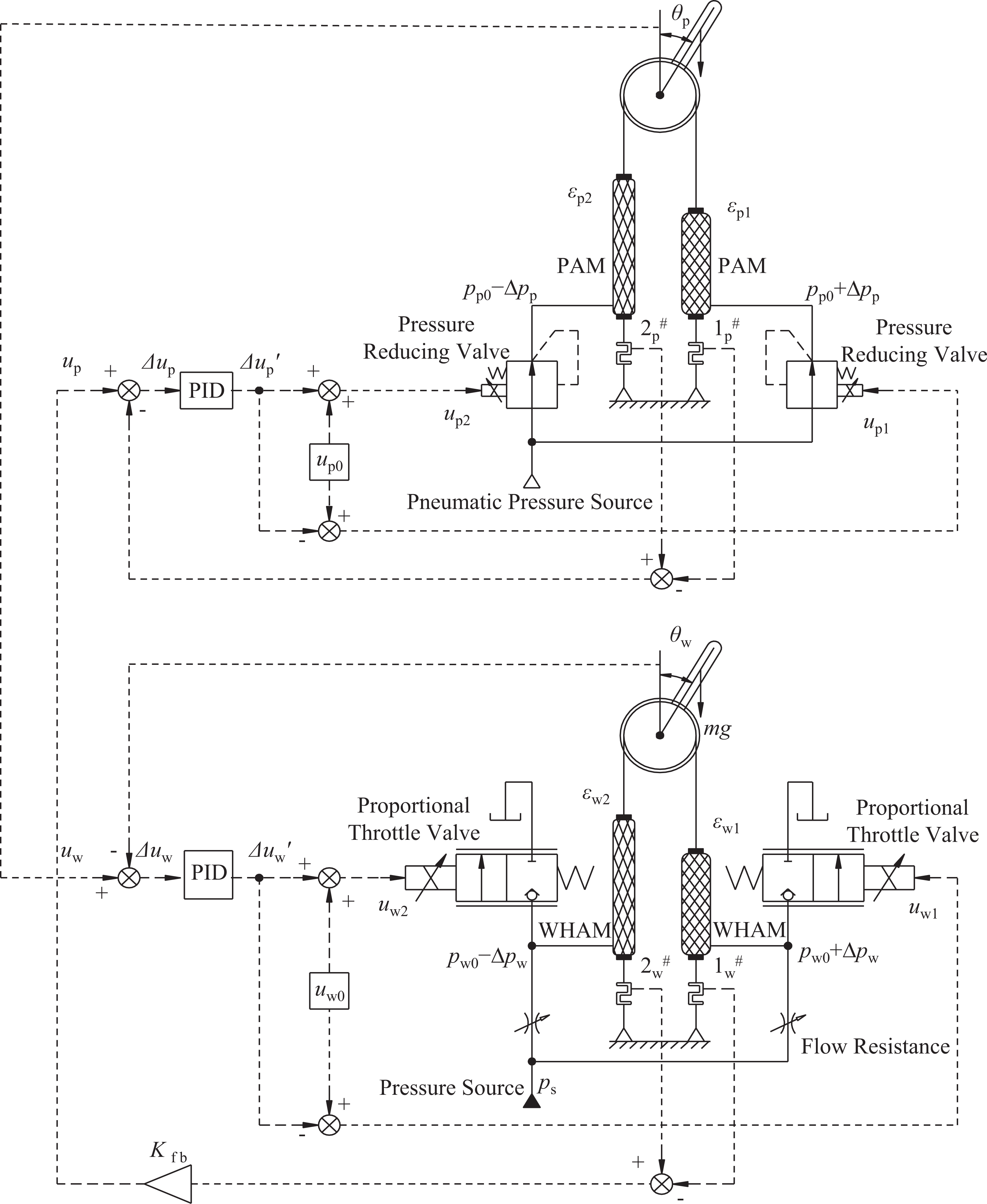
Principle of master–slave artificial muscle control.
The actuation of the two WHAMs is controlled by two proportional throttle valves, and the operation of the system is performed as follows: first, the initial voltage signal u is input to the WHAM control system; next, after the tracking error enters the PID controller, the voltages of the two proportional throttle valves become u
w1 = u
w +
Water hydraulic artificial muscle joint system model
Two WHAMs have the same pressure, p 0, and contraction ratio, ε 0, before the controlling valves are actuated. After water is filled into the WHAMs, the pressure of WHAM 1 becomes p 1 = p 0 + Δp and its contraction ratio becomes ε 1 = ε 0+Rθ/l 0; the pressure of WHAM 2 becomes p 2 = p 0 − Δp, and its contraction ratio becomes ε 2 = ε 0 − Rθ/l 0, where the radius of the mechanical joint runner is R and the angle of rotation is θ.
When assuming zero load and friction, WHAMs 1 and 2 output the same force. However, when the load cannot be neglected, the two force outputs are different. According to the improved combination model proposed by Meller et al., 19 the force produced by a WHAM is

where the strain-tuning parameter κ ε reduces the modeled maximum contraction to become close to the actual value. The force-tuning parameter κ F corrects the modeled force.
The antagonistic muscle output torque T can be calculated as

Combining

where

In equation (3), θ is the relative angle between the new position and the initial position, and for a certain muscle, K 1 and K 2 are both constants. When we plug p 1 = p 0 + Δp and p 2 = p 0 − Δp into equation (3), we get

The joint torque can be expressed as

where J, μ, K, m, and L are the rotary inertia, viscous drag coefficient, elastic coefficient, rod mass, and rod length of the joint, respectively.
The transfer function of the water pressure valve in the hydraulic circuit is

The flow rate to WHAM, q 1 and q 2, can be approximately calculated as 13
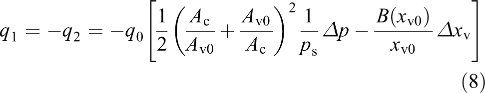
where A c, A v0, p s, x v0, and Δx v0 are the flow area of fixed flow resistance, the effective flow area of the proportional throttle valve, the pressure of the pump, the initial spool displacement, and the valve spool displacement, respectively.
The flow in/out of the two WHAMs, q 1 and q 2, can also be calculated as
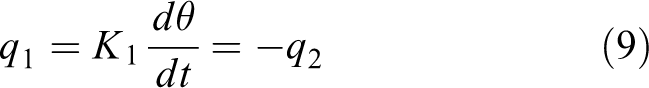
Combining equations (6), (7), and (8) yields

The transfer function is

where

The mathematical model of the WHAM joint has been established. The WHAM joint frequency response curve was derived using MATLAB, as shown in Figure 2. In the low-frequency band, the experimental curve is basically consistent with the simulation curve, and the frequency of rotation angle is similar. In the high-frequency range, the experimental curve deviates from the simulation curve because of factors such as mechanical joint friction and spool damping. The main parameters of the WHAM joint are given in Table 1.

Frequency characteristic curve of the WHAM joint position control system. (a) Amplitude-frequency curve and (b) phase-frequency curve. WHAM: water hydraulic artificial muscle.
The main parameters of the WHAMs joint.

WHAM: water hydraulic artificial muscle.
Position/force PID control
The master–slave artificial muscle joint system is composed of two control loops, of which one is the WHAM joint position PID control loop and the other part is the PAM joint torque PID control loop. The two high-strength WHAMs were built by our research group. The original length L 1 = 207 mm and L 2 = 203 mm. The output force F 1 = 10,150 N and F 2 = 10,020 N at a working pressure of 4 MPa. The maximum contraction ratio is 50 mm, and the maximum working pressure can reach 10 MPa. The WHAM driving characteristics are shown in Figure 3. The WHAM joint system is a two-input single-output system. The input is the pressure of two plane-facing WHAMs. The output is the rotation angle of the joint. When the joint moves from one position to another, the two artificial muscles can have different pressure input combinations. Determining the static characteristics of the WHAM joint is a prerequisite for implementing the master–slave control. The pressure p 2 of the fixed no. 2 muscle is 1, 2, 3, 4, and 5 MPa, and the pressure p 1 of the artificial muscle of the no. 1 pressure is gradually increased from 0.2 MPa to 4 MPa, and the range of the joint angle is obtained under different pressures at the same time. The theoretical and test curves are shown in Figure 4. Both the theoretical and test curve’s slopes decrease with the increase of pressure for muscle no. 1. The range of the rotation angle decreases with the increase of pressure for muscle no. 2. The difference between the theoretical and experimental curves is that all the five theoretical curves increase from 0°, while parts of the experimental curves don’t. The rotation angle of the theoretical curve under symmetrical pressure is 45°, and the test curve isn’t, because the two muscles’ driving characteristics are close but not same. In addition, there are differences in the geometric parameters of the two muscles, especially the braided angle that has the greatest impact on it.

Drive characteristics of the WHAMs. WHAMs: water hydraulic artificial muscles.
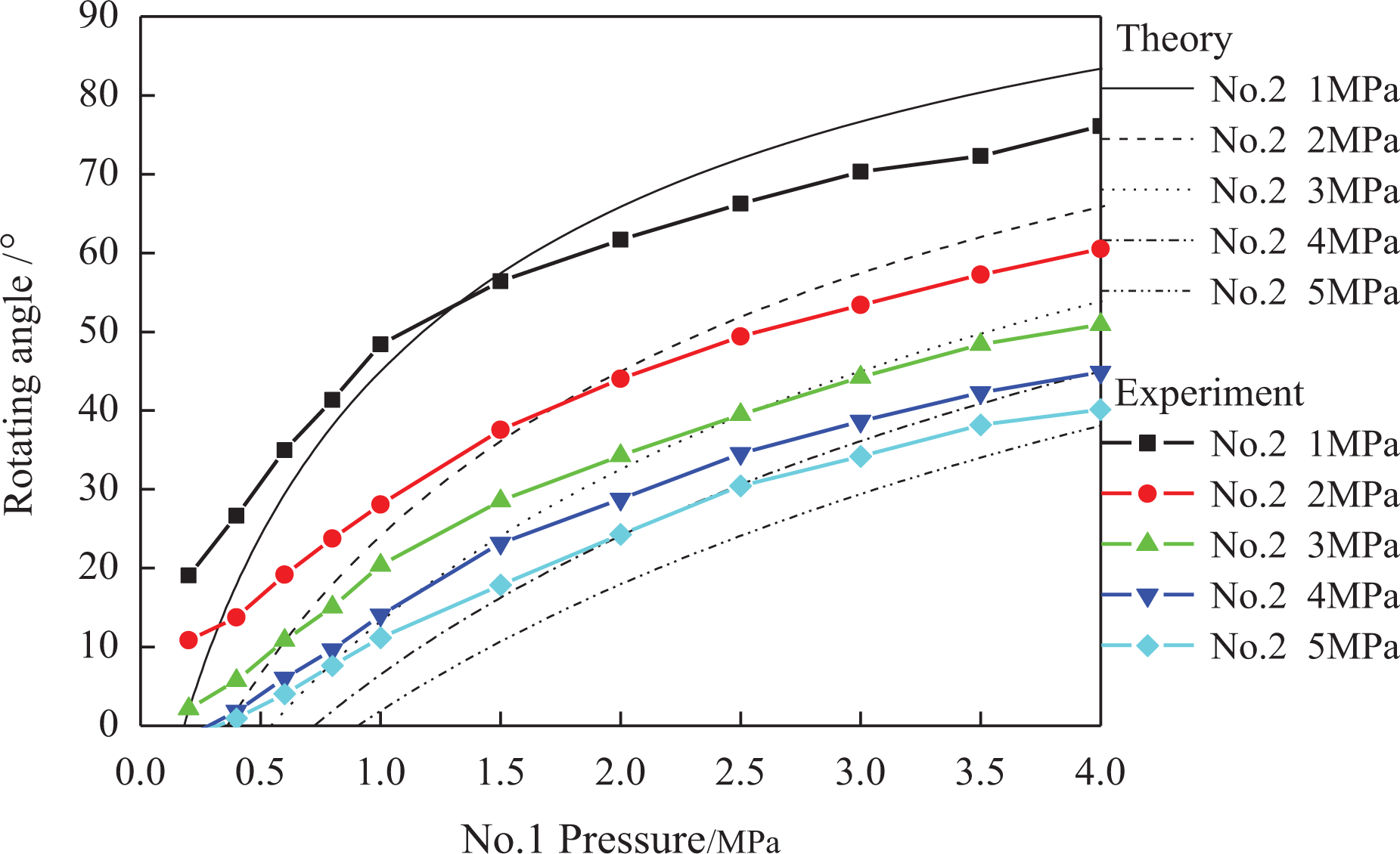
Theoretical and test curves between the WHAM joint angle and pressure. WHAM: water hydraulic artificial muscle.
WHAM joint position PID control
The WHAM joint system is composed of three parts: a mechanical joint, pressure controller, and data acquisition system. The pressure of two WHAMs in this circuit is controlled by a bleed-off circuit that contains a one-way throttle and proportional throttle valve. MATLAB Simulink is used to program the control loop, and then, the program is uploaded to a PCL-726HG data acquisition card controlling the proportional throttle valve to achieve the dynamic control of the circuit pressure. The two throttle check valves are set to a certain degree of opening. The proportional valve voltage adjustment range is between 0 V and 10 V.
To make the joint operating angle range sufficiently wide, the proportional valve that controls WHAM 1 takes a reducing voltage signal that ramps from 10 V to 0 V, and the proportional valve that controls WHAM 2 takes an increasing voltage signal that ramps from 0 V to 10 V.
Using symmetric pressure control method, the two muscles are set at the same initial pressure, and then, the pressure of WHAM 1 is increased, while the pressure of WHAM 2 is reduced by the same amount. In Simulink, a program is compiled to control the hydraulic joints. As shown in Figure 5, as the voltage regulation range of the proportional valve is between 0 V and 10 V, a 5-V initial signal is set for the two proportional valves. The electrical signal measured by the angle displacement sensor is amplified by the gain to obtain the corresponding angle. The deviation of the angle and the input rotation signal are adjusted by the PID controller so that when the supply voltages of the two proportional valves change, the pressure of the two WHAMs can be adjusted to achieve the tracking control of the input rotation signal.

Step input joint position PID control block diagram. PID: proportional–integral–derivative.
To achieve the master–slave control system, the position signal of the PAM joint needs to be fed back into the WHAM joint. The master–slave joint position control system circuit consists of the PAM joint control system and the WHAM joint control system as well as an industrial computer, acquisition card, sensor, and other components of the PID control system.
The block diagram of the control system is shown in Figure 6, and the 2.5-V initial voltage signal is sent to the pneumatic proportional reducing valves. In the test, a reference position signal was sent to the PAM joint, and an angle displacement sensor measured the current position. This position signal and the input position signal of the PAM joint formed a closed loop. Using a PID controller, we can achieve position signal tracking of the PAM joint. The obtained PAM joint position signal is subsequently used as the input for the WHAM joint to control the angular position of the WHAM in a closed loop.
Master–slave joint position PID control block diagram. PID: proportional–integral–derivative.
PAM joint torque PID control
To provide load torque feedback from the WHAM to the PAM joint, the control of PAM needs to be studied. It is necessary to first understand the torque response range of the PAM joint, so experiments for PAM torque characteristics were designed. In the experiment, a setting pin was used to hold the PAM joint in place through three drilled holes ranging within a 90° angle on the joint wheel and supporting plate. Given that the voltage adjusting range of the pneumatic pressure-reducing valve is between 0 V and 5 V, the input signal was set to increase from 0 V to 5 V for pressure-reducing valve 1 and to be reduced from 5 V to 0 V for pressure-reducing valve 2.
The results are listed in Table 2, and the joint output torque ranges were similar for all three positions. As shown in Figure 7, the linearity of the curve satisfies the need for torque control. An experimental method was used to obtain the appropriate PID parameters for the system. The torque range of the PAM joint is −12 to 22 Nm, and the torque signals were tested within this range. After several experiments, it was determined that when the PID parameters were 0.005, 0.15, and 0, the system response was better.
Torque scope of the PAM joint with different positions.

PAM: pneumatic artificial muscle.

Relationship between the joint torque and time.
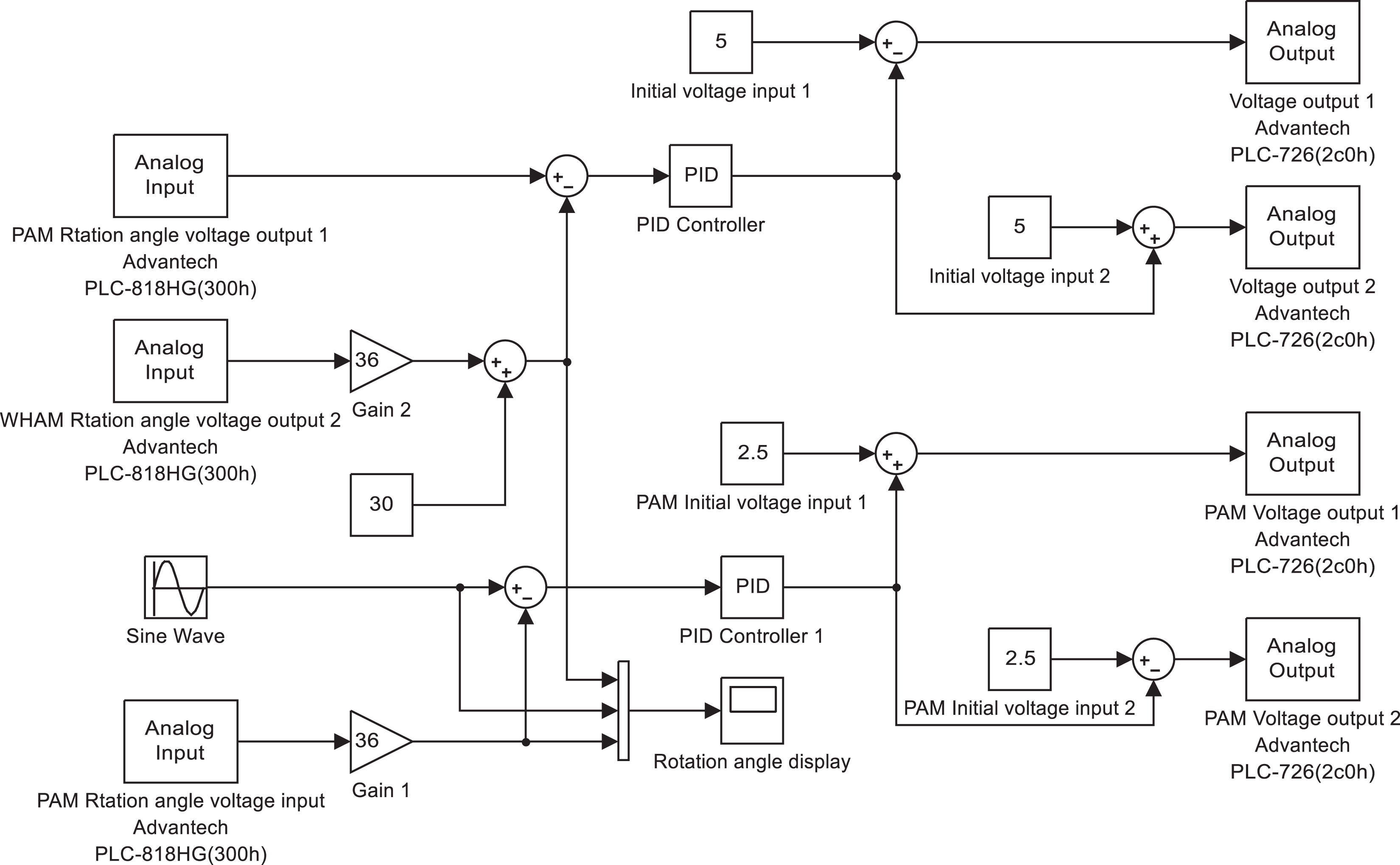
The PAM joint torque control system also employed a symmetrical pressure control method for which the experiment control system in Simulink is shown in Figure 8. The master–slave artificial muscle joint torque control system is similar to the master–slave joint position control system. The difference is that a load was required on the WHAM joint. In the experiment, an inertial load was applied by suspending a weight on the WHAM joint. The block diagram of the control system is shown in Figure 9. The upper part is the position control system where the input signal is the PAM joint angle and the output is the WHAM joint angle signal. The lower part is the torque control system in which the WHAM joint torque is the input signal and the output is the PAM joint torque signal. As the torque of the PAM joint output is far less than that of the WHAM joint, gain 9 was set to balance the signal.

Sine-wave input joint torque PID control block diagram. PID: proportional–integral–derivative.

Master–slave joint torque PID control block diagram. PID: proportional–integral–derivative.
Master–slave control experiment
A test bed was set up as shown in Figure 10. The inflation pressure of two PAMs was regulated by an independent pressure-reducing circuit. The PAMs employed in this test system are produced by Festo, Germany, with an original length L 0 = 300 mm and a maximum output force F max = 2000 N at 0.6 MPa. The maximum contraction ratio of the PAM is 25%. A pressure-reducing valve produced by the SMC Corporation was selected. The maximum output pressure is 0.9 MPa, and the maximum flow is 5000 L/min. Each WHAMs pressure can be adjusted independently. High-pressure water is provided by a pump and then divided into two circuits. The two hydraulic circuits are both hydraulic bridges that consist of a throttle valve and a proportional valve, which adjust the pressures of the two WHAMs.

Configuration of the master–slave muscle joint test bench.
A sinusoidal signal with an amplitude of 30° and frequency of 1 rad/s was programmed and sent to the PAM control circuits. The results are shown in Figure 11. The response time of PAM is 0.5 s, while the response for WHAM is 1.0 s. The slow response of the pneumatic valves caused a lag in the tracking displacement. Moreover, the slow response led to a large lag in the rotating angle of the slave joint. Since the fluid medium of the PAM has compressibility, it does not shrink or elongate immediately when the PAM receives the action signal, which causes a response lag. However, the WHAM is arranged in the master side. There is a delay in the communication from the master side to the slave side, so the WHAM’s response lags behind the PAMs. In addition, the friction in the mechanical system is also one of the causes for the response lag.

Master–slave joint position control response curve with sine-wave input.
In practice, the slave WHAM joint can be controlled by operating the master PAM joint because the rotating angle of the master joint can be fed into the controller to steer the slave joint for tracking the displacement of the master joint. The results of the tracking experiments are shown in Figure 12. Eliminating the impact of the position control of the PAM joints, the response of the WHAM joint position has been significantly improved. However, due to the nonuniform input from a human hand, we would still need the valve control for the PAM joints in cases where uniform operation is required.

Master–slave joint position control response curve with random signal input.
As shown in Figure 12, the response of the WHAM joint has a 0.5-s lag when the cycle of the PAM joint input is approximately 4.0 s, and the magnitude also deviates from the reference within 9.6°. To analyze the factors that affect the performance of master–slave control, the following tests were designed. The load level set in the test should be similar to the strength that the human body can provide. An adult can lift a weight of 10∼15 kg when the arm is straight. Therefore, 5 kg, 15 kg, and 25 kg loads were applied to the WHAM joint with gains set at 3, 6, and 8, respectively. The operator pushed the PAM joint in the test. The results are shown in Figures 13, 14, and 15, respectively.

Rotation angle and torque of the joints at 5-kg load and a gain of 3. (a) Rotation and (b) torque.

Rotation angle and torque of the joints at 15-kg load and a gain of 6. (a) Rotation and (b) torque.

Rotation angle and torque of the joints at 25-kg load and a gain of 8. (a) Rotation and (b) torque.
As shown in Figure 13(a), the operator operates the PAM joint so that it can rotate within a range of 100° to 160° with a load of 5 kg and a gain of 3. There are four peaks that exist within 40 s, which indicates that at the completion of four reciprocating motions, there is an approximately 0.8-s lag of the WHAM joint tracking the PAM joint, and the maximum angle error between the WHAM and PAM joint is 4.4°.
As shown in Figure 13(b), the red curve represents the torque of the slave WHAM joint. To compare the torques between the master and the slave joints, the black curve was drawn with three times the torque of the slave PAM joint. The torque of the WHAM joint varies from 6.5 Nm to 20.4 Nm, and the triple torque of the PAM joint varies from 6.4 Nm to 21.3 Nm. The actual torque range of the PAM joint is between 2.2 Nm and 7.1 Nm.
As shown in Figure 14(a), the operator controls the PAM to rotate within the range of the upper and lower amplitudes between 95° and 165° with a load of 15 kg and a gain of 6. The results showed four peaks, which indicates the completion of four reciprocating motions. A 1.0-s lag of the WHAM to the PAM is found; the maximum error of which is 2.9°. As shown in Figure 11(b), the torque of the WHAM joint varies from 23.4 Nm to 43.6 Nm, and the sextuple torque of the PAM joint ranges from 22.9 Nm to 43.9 Nm. The actual torque of the PAM joint varies from 3.8 Nm to 7.3 Nm.
As shown in Figure 15(a), the operator controlled the PAM to rotate within a range between 100° and 165° with a load of 25 kg and a gain of 8. The result shows one peak between 0 s and 20 s, which suggests that there is a completed reciprocating motion. Between 20 s and 40 s, there are two peaks, which means that there are two completed reciprocating motions. A 0.4-s lag of the WHAM to the PAM is found, and the maximum error is 6.4° for the first 20 s. The maximum error of the tracking signal in the next 20 s was 9.7°.
As shown in Figure 15(b), the torque of the WHAM joint varies from 37.0 Nm to 66.3 Nm, and the octuple torque of the PAM joint ranges from 32.7 Nm to 72.4 Nm. The actual torque of the PAM joint varies from 4.1 Nm to 9.1 Nm. The changes in torque among Figure 10(b), Figure 11(b), and Figure 12(b) reflect the load variation.
Experiments showed that under the same load and gain conditions, a faster frequency and higher torque resulted in higher errors.
Based on previous analyses, the last experiment showed that the faster the motion frequency, the larger the position tracking error will be. In previous experiments, the load and frequency were different: The first and the third had a maximum period of 10 s for the first 20 s, but the third had a higher position and torque error, which suggests that under a fixed frequency of movement, the position and torque error went up with load and gain. The second and third had a period of 20 s for the last 20 s, but the third had a higher position and torque error for the last 20 s, which also indicates that the same results occurred. Compared to the second experiment, the first had a lower load but higher frequency; it still resulted in a higher error. In addition, the linearization of the WHAM joint model makes the experimental results deviate from the theoretical results. Investigating the nonlinear factors of WHAM will be the focus of subsequent research.
Conclusions
A master–slave control system of isomorphic artificial muscle joints was studied through system design and experiments. The delay time of the PAM joint is approximately 0.5 s, and the delay time of the WHAM joint is 1.0 s with an input of a 30° amplitude 1 rad/s frequency sinusoidal signal. Applying 5, 15, and 25 kg loads to the WHAM joint and setting the corresponding gains to 3, 6, and 8, the characteristics of the slave WHAM joint tracking the rotation of the master PAM joint were investigated through experiments. The maximum rotation angle tracking error of the slave WHAM joint is 2.9° with a load of 15 kg and a gain of 6. The WHAM joint angle range is approximately 45°–50°. When the load is 5 kg, the WHAM joint output torque is 6.5–20.4 Nm. When the load is 15 kg, the WHAM joint output torque is 23.4–43.6 Nm. When the load is at 25 kg, the WHAM joint output torque is 37.0–66.3 Nm.
The feasibility of a master–slave control system designed in this study for low-frequency operation under water was proved with experiments. The advantages of this master–slave control system, particularly in the field of marine engineering, are listed as follows. Firstly, when WHAM is applied in a slave joint system, there is obvious superior performance. The advantages of WHAM, such as a high force–weight ratio and environmental friendliness, contribute to the light and small design for the underwater device and avoid environmental pollution. Secondly, to make the most of the high force–weight ratio advantage of WHAM and enhance the ability of underwater operations, a gain was set in the loop of the master–slave torque control. Moreover, the master joint system is actuated by PAM, which has low stiffness and excellent pliability that can ensure the safety of the operators. Finally, the master–slave control system of the isomorphic artificial muscle joints can be operated easily. Generally, the operator can control the movement and feel the load of the WHAM slave joint. Thus, the maneuverability and work efficiency of the anthropopathic underwater manipulator are improved.
Footnotes
Declaration of conflicting interests
The author(s) declared no potential conflicts of interest with respect to the research, authorship, and/or publication of this article.
Funding
The author(s) disclosed receipt of the following financial support for the research, authorship, and/or publication of this article: This work was supported by the National Natural Science Foundation of China [Grant No. 51475064], the Program for Liaoning Excellent Talents in University [Grant No. LJQ2015012], and Fundamental Research Funds for the Central Universities of China.