
Abstract
An automatic precision robot assembly system is established. The robot assembly system mainly consists of an industrial robot, three cameras, a micro force sensor, and a specific gripper. The industrial robot is a six-axis serial manipulator, which is used to conduct grasping and assembly subtasks. Two microscopic cameras are fixed on two high accuracy translational platforms to provide visual information in aligning stage for assembly. While one conventional camera is installed on the robotic end effector to guide the gripper to grasp component. The micro force sensor is installed on the robotic end effector to perceive the contacted forces in inserting stage. According to the characteristics of components, an adsorptive gripper is designed to pick up components. In addition, a three-stage “aligning–approaching–grasping” control strategy for grasping subtask and a two-stage “aligning–inserting” control strategy for assembly subtask are proposed. Position offset compensation is computed and introduced into aligning stage for assembly to make the grasped component in the microscopic cameras’ small field of view. Finally, based on the established robot assembly system and the proposed control strategies, the assembly tasks including grasping and assembly are carried out automatically. With 30 grasping experiments, the success rate is 100%. Besides, the position and orientation alignment errors of pose alignment for assembly are less than 20 μm and 0.1°.
Introduction
In recent years, with the wide application of microelectromechanism system in the fields of medicine, aerospace, and precision electronic engineering, precision assembly technology has received more and more attention. 1,2 Precision assembly is to package millimeter-size or less components with micrometer-level precision requirements. 3 Traditional precision assembly is conducted by human, and the manual assembly has the inherent limitations of low efficiency and precision. Besides, it causes high production costs. Automatic precision assembly as a promising assembly technology has been investigated extensively, and numerous of precision assembly systems are established for different applications. 4,5 For example, Wason et al. 6 designed a vision-based micro-assembly system to assemble multiple probes. Xing et al. 7 presented a micro-assembly system with six manipulators to assemble irregular shaped components. Shen et al. 8 designed an automatic high precision assembly system to assemble microparts. In these assembly systems, a large number of assembly methods are proposed to achieve automatic precision assembly.
In general, assembly can be further classified into parallel assembly and serial assembly. 9 Parallel assembly divides the assembly task into several subtasks, and these subtasks are conducted simultaneously. Compared to parallel assembly, serial assembly has lower efficiency. But serial assembly is more suited to complex assembly manipulation for its ability of assembling varying types components with high flexibility. 10 Thus, serial assembly are commonly used in precision assembly. Grasping is one of the most basic assembly tasks. 8,9,11 Traditional grasping control strategies without vision sensors are prone to leading to grasping failure when uncertainties occur in pose estimation. 12 Visual servoing is an effective method to improve success rate of grasping for the promising ability to provide noncontact online information. 9,11 Series of visual servoing control algorithms have been employed in grasping manipulation, which dramatically increases the flexibility and reliability. 11,13 –16 For example, the micro-grasping and micro-joining tasks are performed with visual servoing control. 9 With a simple 2-D gripper, the stable grasping in 3-D space is achieved with 2-D visual information. 14 Combining visual features and a camera on robotic end effector, a visual servoing grasping planning method in dynamic environment is proposed. 15 With an active zoom microscopic camera and nonlinear projective principle, the multiple scale visual information is used for robot micro-manipulation and micro-assembly. 16 According to the relation between hand and eye, the visual servoing-based grasping methods can be divided into two categories, that is, eye-to-hand grasping 13,14 and eye-in-hand grasping. 15,16 In eye-to-hand mode, the working space for grasping is limited. Besides, in order to control the end effector to approach object, it also needs to estimate the relative pose between the end effector and the object in real time. 13,14 With eye-in-hand grasping, the camera can move with the end effector, which expands the working space for grasping. 15,16
The inserting assembly is one of classic assembly modes. 10,17 –20 According to fit type between components, the inserting assembly can be categorized into clearance assembly, transition assembly, and interference assembly. 7 In precision assembly, the interference assembly is widely used. 17 In general, the interference inserting assembly can be divided into two stages, that is, aligning stage and inserting stage. 4,7 The aligning is usually completed based on visual features, 10 while the force-based control strategy is employed in inserting stage due to the visual features are blocked in inserting process. 18 –22 Liu et al. 19 proposed a high precision assembly control strategy. Firstly, the orientation alignment and position alignment are carried out separately. Then the inserting assembly is conducted based on force feedback. Xing et al. 4 proposed a hybrid control structure for precision contacted assembly, which includes a vision-based alignment controller and a force-based inserting controller. Liu et al. 21 presented a high efficient inserting assembly method, which models the inserting process as a stochastic state transition process and the uncertainties in inserting process are described by Gaussian function. Considering multiple points contacted assembly, Wiemer and Schimmels 22 designed a direct admittance selection method for force-guided assembly. Because most of the above precision assembly systems are equipped with multiple independent manipulators and the degree of freedom of each manipulator is limited, the orientation and position alignments are carried out sequentially. 4,7,18 –21 Obviously, the efficiency of the decoupled pose alignment is low. In the works above, the grasping control is not investigated, and the components to be assembled are put on the manipulators by human.
With the characteristics of miniaturization, flexibility, high movement accuracy, and wide working space of industrial robots, the industrial robots are widely employed to automatically assemble objects. 23 For example, Koveos et al. 24 presented a task-based variable impedance method for assembly, which achieves assembly via robot-aided operation in a semistructured environment. Fang et al. 25 designed a robot assembly system for small components assembly, in which a dual-arm robot is used to improve the flexibility and collaboration in automatic assembly. To solve the problems among the precision, mobility, and global view in vision-based grasping, Muis and Ohnishi 26 used two robots achieve grasp positioning. The industrial robot assembly systems are mainly employed to assemble mesoscale or macroscale components. Because of high precision requirements in precision assembly, 27 it still be a challenge to achieve precision assembly with industrial robots.
Considering the shortages of existing assembly systems and assembly methods, an automatic robot precision assembly system used for assembling small components with high efficiency is established. The robot assembly system mainly consists of an industrial robot, a gripper, three cameras, a micro force sensor, and a host computer. The industrial robot is used to conduct the whole assembly manipulation. The gripper is a specific vacuum adsorptive device, which is used to grasp small components. One camera with large field of view is installed on the robotic end effector to guide robot to locate components in large working space. Two microscopic cameras with small field of view and high resolution are used to measure the pose errors of components in aligning stage for assembly. The micro force sensor provides force information in inserting stage. Based on the designed robot assembly system, the classic assembly manipulation: grasping and assembly are conducted. An “aligning–approaching–grasping” control strategy is designed for grasping subtask. The proposed grasping method provides an efficient solution for eye-in-hand grasping with monocular vision, and it is suitable to be used in the engineering applications for its high success rate and low hardware cost. Besides, the Image Jacobian matrix needs to be calibrated only once, which is more flexible compared to existing grasping methods. An “aligning–inserting” control strategy for assembly subtask with microscopic vision and force perception is proposed. The assembly experiments of two millimeter-scale components are carried out to verify the practicability and efficiency of robot assembly system. The main contributions of this article are:
A novel automatic robot assembly system is established for precision assembly, which can automatically complete classic assembly tasks with high efficiency. A three-stage “aligning–approaching–grasping” control method for grasping is proposed, which improves the grasping success rate. A two-stage “aligning–inserting” assembly control method is designed, which improves the efficiency of precision assembly.
The rest of this article is arranged as follows. The designed precision robot assembly system including the hardware system and the software system is described in the second section. The automatic precision assembly control, which includes the assembly control strategies and process, the grasping and assembly controllers, is presented in the third section. In the fourth section, the precision assembly experiments are conducted on the established robot assembly system. In the final section, the conclusions are presented.
Assembly task
The task of this article is to assemble two small cylindrical components that are shown in Figure 1. The whole assembly task consists of two subtask: grasping and assembly. The three-stage “aligning–approaching–grasping” grasping method is focused on aligning, approaching, and grasping components. And we take grasping component A as example to explain the grasping method. Of course, the component B can be picked up with the proposed grasping control method and put on the assembly platform automatically. It is not necessary to describe or discuss the grasping process for the components A and B repeatedly. The component B is assumed to be put on the assembly platform in advance in order to make this article more compact. The assembly subtask includes two substages, that is, aligning stage and inserting stage. The goals of aligning stage for assembly are to align the orientation of component A to component B and make the relative position between component A and component B reaches a desired status. While the goal of inserting stage is to complete interference inserting assembly without damaging the components.
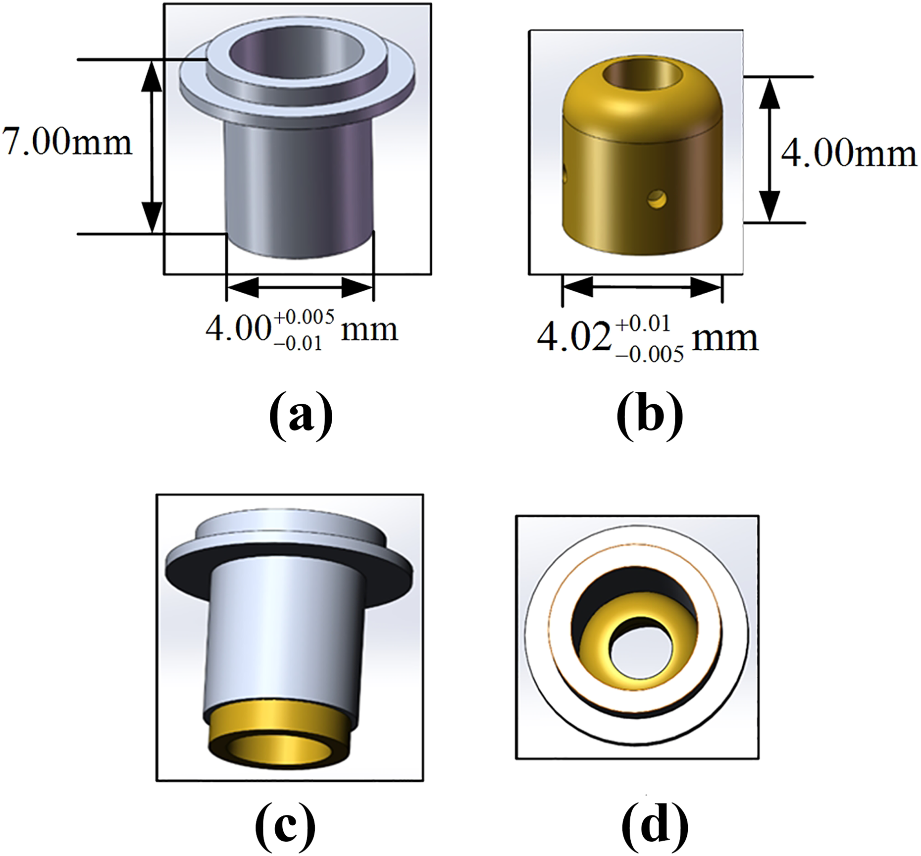
Components to be assembled. (a) Component A. (b) Component B. (c) Components in assembly process. (d) Assembled component.
The main difficulties of this assembly task can be summarized as follows. Design of the hardware system: To ensure the high success rate of grasping subtask and improve the efficiency of assembly subtask, the configuration of the robot assembly system is one of the key points. The hardware system configuration consists of the model selection and the installation of hardware devices. In particular, when designing the gripper used for grasping components, it needs to ensure the reliable grasping and avoid blocking component’s image features. Control strategy for grasping subtask: According to the configuration of robot assembly system, the central axis of the gripper is approximately parallel to the optical axis of camera installed on robotic end effector. The camera cannot directly observe the end of the gripper, which makes the grasping is an open-loop control based on vision guidance. In order to improve the success rate of grasping, it is necessary to design a reasonable and applicable grasping control strategy. Control strategy for assembly subtask: To improve the efficiency of aligning stage for assembly, the orientation and position alignments are expected to be conducted simultaneously. However, how to keep components in the microscopic cameras’ small field of view in aligning stage is still a problem. In addition, due to the two components are thin-walled parts and the inserting assembly is interference assembly, it is necessary to consider how to design inserting control strategy to protect thin-walled components from damage.
Precision robot assembly system
Hardware system
A robot assembly system is established as shown in Figure 2. The hardware system mainly consists of a robot system, a vision system, a force sensor, a specific gripper, two translational platforms, a rotational platform, and a host computer. The robot system includes an industrial robot and a robot controller. The vision system includes three cameras: camera 1, camera 2, and camera 3. Camera 1 and camera 2 are microscopic vision. While camera 3 is conventional vision. The gripper is adsorptive cylindrical structure.
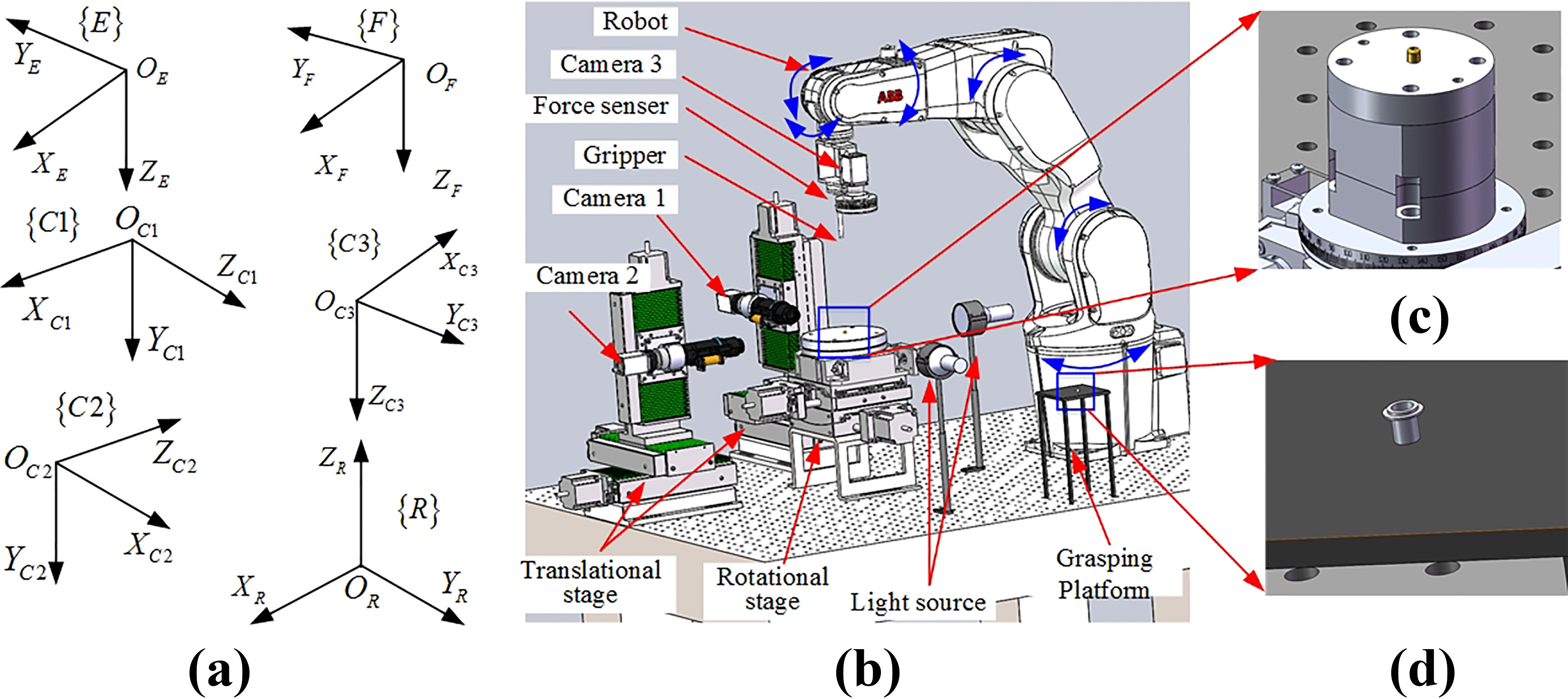
The configuration of the robot assembly system. (a) The established frames. (b) The robot assembly system. (c) Component B on the assembly platform. (d) Component A on the grasping platform.
Robot system
The ABB IRB1200 industrial robot is a six-axis serial manipulator. The resolution of each axis is approximately 0.01°. The reach and position accuracy of the robot are 703 mm and 0.02 mm, which fulfills the requirements of grasping in large working space and high precision requirements of assembly. In addition, the robot system is equipped with an IRC5 controller. With the IRC5 controller, we can control the robot to conduct assembly task.
Vision system
The resolution of the three cameras are 2448 × 2050 pixels. The microscopic camera 1 and camera 2 are fixed on high accuracy translational platforms. The optical axes of two microscopic cameras are approximately perpendicular. The two microscopic cameras are equipped with ring light source, coaxial light source, and collimated light emitting diode (LED) backlight source. The camera 3 is mounted on robotic end effector. It is equipped with a ring light source. The ring light source is installed in front of the camera’s lens to make camera observe the components’ features clearly. The coaxial light source is installed inside the camera’s lens to improve the imaging of the planar reflective components. The backlight source is installed on the extension line between the camera’s optical center and the components. It can make the contour features of components clearly and easily be extracted. The microscopic cameras are equipped with NAVITAR 6000 motorized focusing lens, while the conventional camera 3 is equipped with a Computer M2518-MPV lens whose focal length is 25 mm.
Force sensor
The fit style between component A and component B is interference fit. To measure the contacted forces in inserting stage, the ATI six-axis micro force and torque sensor Nano43 is employed. The force sensor can measure force and torque simultaneously. The force sensor is mounted between the robotic end effector and the gripper. The axes XF, YF, and ZF of force sensor are approximately parallel to the axes XE, YE, and ZE of robotic end effector. The range of force sensor is within [−18,18] N via configuring the calibration file, and the resolution of force sensor is 4 mN. In this article, only the contacted forces are used in inserting assembly.
Absorptive gripper
The designed adsorptive gripper is shown in Figure 3. The gripper is internal hollow cylindrical structure. The air entrance of the gripper is connected with a suction device, and the end of the gripper has lots of holes. When the gripper approaches component A, component A can be picked up due to the adsorption force. The designed gripper can grasp component without blocking the visual features of component A. In addition, the end of gripper is designed into a bell mouth. The diameter of the bell mouth is larger than the outer diameter of component A by 0.01 mm, which can improve the success rate of grasping.

The specific gripper.
Various frames are established for convenience, which are shown in Figure 2. The robot base frame {R} is established on the robot base. The axis XR points to the front of the robot when the robot is in the default initial pose. The axis ZR points to the second joint from the base. The axis YR is set according to the right-hand rule. The robot end frame {E} is established on the robotic end effector with origin in its default tool center. The frame {E} moves as the robotic end effector is adjusted. The force frame {F} is established on the force sensor. The axes XF, YF, and ZF are approximately parallel to the axes XE, YE, and ZE. The frames
Software system
As shown in Figure 4(a), the software system mainly consists of four modules: human–computer interaction module, communication module, control algorithm module, and image acquisition and processing module. The human–computer interaction module includes the input and output devices and the data display interface. The operation interface of the robot assembly system is shown in Figure 4(b). The operator can control the assembly task and obtain the status of assembly system through the human–computer interaction module. The communication module includes the communication programs with cameras, the communication programs with translational and rotational platforms, the communication programs with force sensor, and the communication programs with robot. The control algorithm module mainly includes assembly control programs, and it is the core of assembly software system. The image acquisition and processing module mainly includes image acquisition and image processing. The basic image processing programs includes image filter, edge detection, and image feature extraction.

Software system of robot assembly system. (a) The modules of software system. (b) The operation interface of assembly system.
In addition, the assembly software in the computer is written with C++ language based on Microsoft Foundation Classes (MFC) library. While the programming language of ABB robot is RAPID. The RAPID programming language is designed for ABB robots and can be used in all ABB robotic products. The socket communication is employed between the host computer and the robot.
Automatic assembly control
Assembly control strategies and process
In this article, we mainly focus on the grasping and assembly subtasks.
Grasping subtask
In the grasping subtask, the “aligning–approaching–grasping” control strategy is proposed. In the aligning stage for grasping, the image-based visual servoing is employed to make the image features of component A coincide with the desired image features. In the approaching stage, the robotic end effector moves −P to make the gripper approach component A. In the grasping stage, the gripper picks up component A based on absorption force.
The image point feature is sensitive to the translational movement perpendicular to the optical axis of camera, and the image area feature is sensitive to the translational movement parallel to the optical axis of camera.
28
In the aligning stage of grasping subtask, the center point feature and contour area feature of component A are manually selected as the image feature for image-based visual servoing. The desired and current image features of component A are denoted as
The automatic grasping process is shown in Figure 5. In each control cycle, the camera 3 captures the image of component A, and component A’s edge points are extracted based on the grayscale of image automatically. Then the edge of component A is determined via Random Sample Consensus (RANSAC) method. The center

The grasping process.
Assembly subtask
In the assembly subtask, the “aligning–inserting” control strategy is employed. In the aligning stage for assembly, the image-based visual servoing is used. And in the inserting stage, the force-based feedback control is used.
In aligning stage for assembly, the point feature and line feature are selected as the image features for visual servoing control. The point feature is used for position alignment, while the line feature is used for orientation alignment. The center of component A’s lower edge line in the images of microscopic cameras is selected as the point feature of component A. The center of component B’s upper edge line in the images of microscopic cameras is selected as the point feature of component B. The component A’s central axis and component B’s central axis are selected as the line features. And the angle of the central axis is used to represent the line feature. In the visual servoing control, the image features are automatically extracted and tracked by designed region of interest.
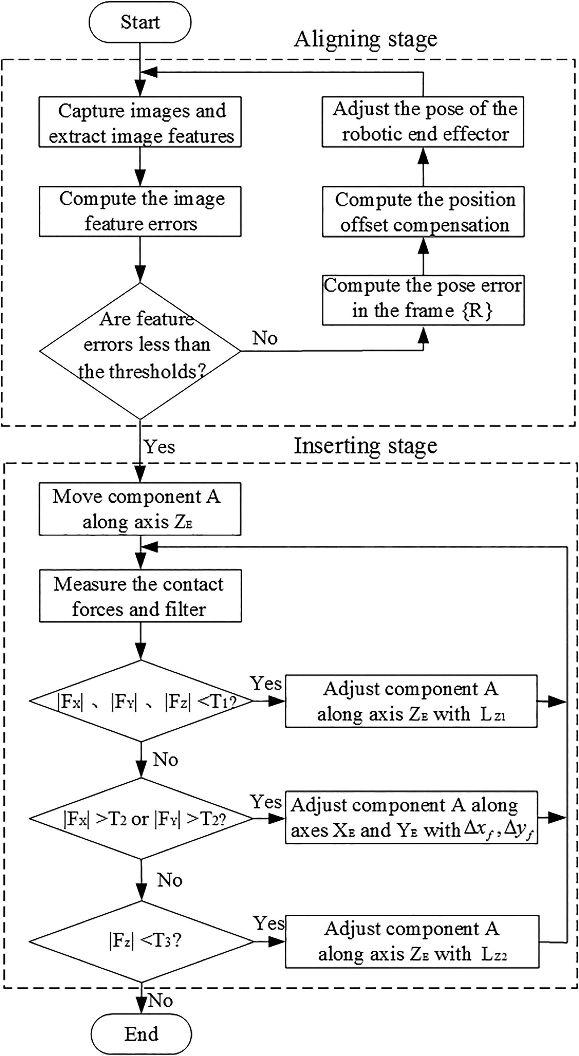
The automatic assembly process is shown in Figure 6. In each control cycle, the microscopic cameras capture the images of component A and B. The edge points of two components are extracted based on the grayscale of images. Then the two side edge lines and lower (upper) edge line of component A (B) are determined via RANSAC method. The average line of the two side edge lines is set as component A (B)’s central axis. The point features and line features of two components are extracted and feature errors are calculated. If the feature errors are larger than the designed thresholds, the corresponding pose errors in the frame {R} are computed with image Jacobian matrix. The position offset compensation of component A due to robotic end effector’s orientation adjustment is computed from (11) and (14). The pose of the robotic end effector is adjusted. Until the feature errors are less than the thresholds, the aligning stage for assembly finishes. The inserting stage starts automatically. During inserting process, the force-based feedback control strategy (15) is used. If the forces FX, FY, and FZ are less than T1, it indicates that the two components do not contact. Then component A is moved along axis ZE to conduct inserting. When the contacted force FX or FY is larger than T2, it indicates that component A needs to be adjusted along axis XE and YE. Then component A is moved along axis ZE until the contacted force FZ is larger than T3, the inserting stage finishes.
The assembly process.
Controller design for grasping
In the aligning stage for grasping, the image-based visual servoing is used, and the incremental proportional-integral (PI) controller is designed as follows

where lower mark k and
Controller design for assembly
Position offset compensation
In aligning stage for assembly, the orientation adjustment of robotic end effector with respect to frame {R} will lead to the position offset of component A. The position offset may cause component A moving out of the microscopic cameras’ small field of view. Based on the differential transformation between frame {R} and frame {E}, the position offset of component A resulting from orientation adjustment is computed.
Given the pose of robotic end effector with respect to frame {R} as T with

where
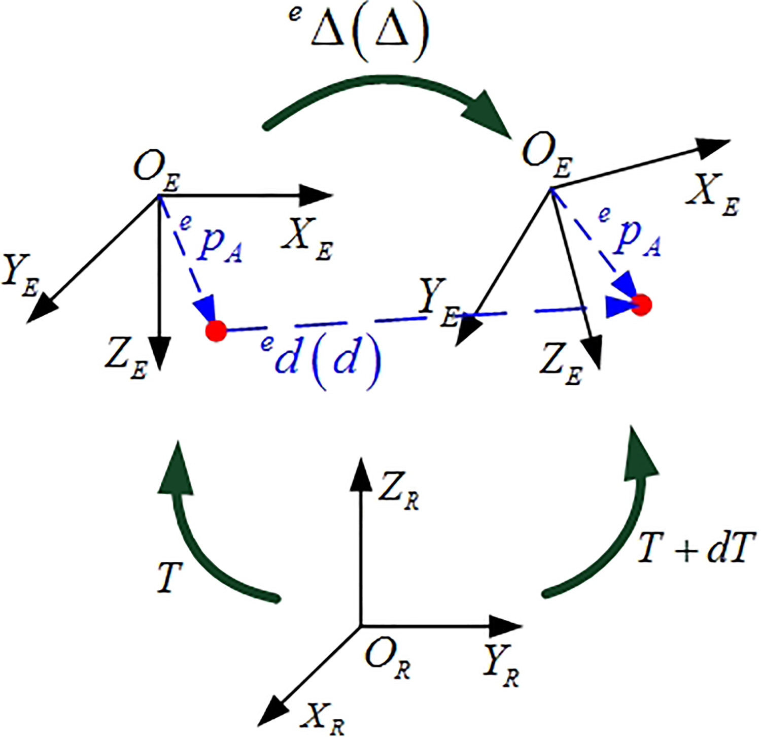
The differential transformation for position offset compensation.
The differential transformation in the frame {R} can be expressed as

The corresponding differential transformation in the frame {E} yields

where
With equivalent differential transformation, equations (3) and (4) satisfy

Combining (3) and (5), the differential transformation (4) can be rewritten as

Since component A is grasped by robotic end effector, the position of component A with respect to frame {E}, that is,
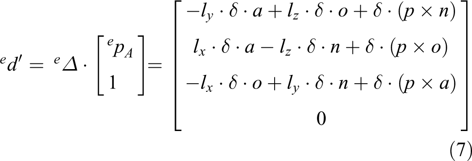
The differential translation of component A with respect to frame {E} can be determined from (7)

According to equivalent differential transformation, the differential translation of component A in the frame {R} yields

Combining (8) and (9), the differential translation of component A with respect to frame {R} can be further written as
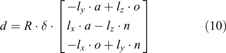
The position offset compensation in the frame {R} is
Aligning control design
The image-based incremental PI controller used for orientation alignment is designed.

where lower mark k and
In position alignment control, the desired position of component A is computed based on the position and orientation of component B. The orientation of component B in the frame {R} is estimated firstly. As shown in Figure 8, in the image of microscopic camera 1, we extract two feature points A and B on the central axis of component B. In the image of microscopic camera 2, two feature points C and D on the central axis of component B are extracted. Then the orientations of component B in images of microscopic cameras are

where

Orientations of component B in images. (a) Image captured by camera 1. (b) Image captured by camera 2.
As shown in Figure 9, the desired alignment position for component A yields

where

The desired image features in aligning stage for assembly.
The position adjustment for pose alignment is

where lower mark k and
Inserting control design
In the inserting stage, the force-based feedback control law is given
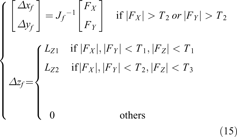
where
Experiments
Robot assembly system and Jacobian matrices calibration
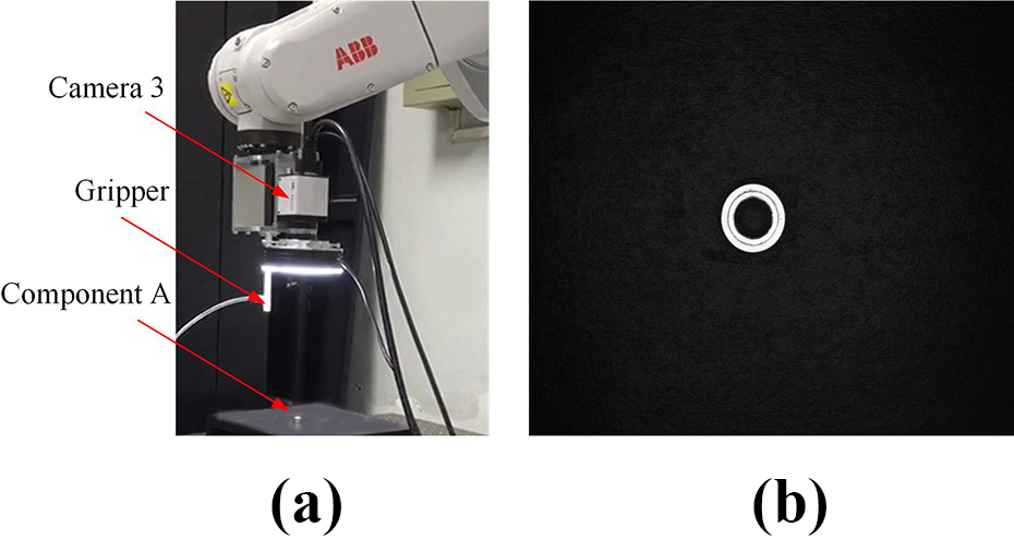
The established robot assembly system is shown in Figure 10(a). The components to be assembled are shown in Figure 10(b), and both components are small parts with cylindrical symmetry structure.

The robot assembly system and components. (a) Robot assembly system. (b) Components to be assembled.
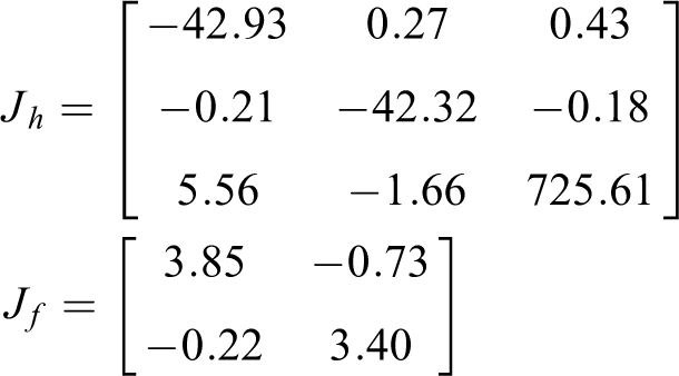
The Jacobian matrices Jr, Jt, Jh, and Jf are calibrated with active motions. 29 In calibrating Jh, the depth of robotic end effector changes little around the depth of alignment position, which can guarantee the stability of the control system when the image Jacobian matrix of the desired position is used in image-based visual servoing. 30 While in calibrating Jr and Jt, the robotic end effector rotates and moves in the microscopic cameras’ clear imaging planes, respectively. Then the Jacobian matrices can be computed according to least square method.

Grasping experiments
The desired image features of component A and the position change P in grasping subtask are recorded as
Status of camera 3 and component A’s desired image after aligning stage for grasping. (a) Status of camera 3. (b) Component A’s desired image.
The position error in aligning stage for grasping is shown in Figure 12. It can be seen that the position feature error reduces quickly and steadily. The aligning stage for grasping finishes after eight steps, and the time-consuming is 10 s.

Position error in aligning stage for grasping.
Once the aligning stage for grasping finishes, the gripper moves −P to make the gripper approach component A. Then the gripper grasps component A with absorption force. The total time-consuming for grasping subtask is 22 s.
In comparison experiments, the position-based visual servoing method in Yacine and Rosmiwati 31 is used in aligning stage for grasping. Thirty grasping experiments are conducted using different batches but the same kind of component A. With the 30 grasping experiments, the success rate of the proposed method is 100%. While the success rate of the method in Yacine and Rosmiwati 31 is 90%. The standard deviation, absolute average, and Root Mean Square (RMS) of position errors in the frame {E} are listed in Table 1. Besides, the position alignment errors and the standard deviations of the 30 comparative experiments are given in Figure 13. The red circle represents position alignment error with the proposed method, and the red line passing through the red circle represents corresponding standard deviation. The blue asterisk represents position alignment error with comparative method in Yacine and Rosmiwati, 31 and the blue line passing through the blue asterisk represents corresponding standard deviation. From the experiments, we can see that the proposed grasping strategy has high precision and grasping success rate. With the position-based visual servoing, the component A’s 3-D position in the frame {C3} is computed with the geometrical algorithm in Chen and Huang. 32 The accuracy of position measurement is low. Besides, the position-based visual servoing needs to calibrate the intrinsic and extrinsic parameters of camera 3. Due to the small depth of field of camera 3, the defocused calibration method in Ding et al. 33 is used, and the calibration process is complicated. Generally speaking, the image Jacobian matrix in image-based visual servoing methods is the function of depth, so it is necessary to estimate the depth. Different from the existing image-based visual servoing methods, the image area of component A is selected to indicate the gripper’s depth in our method. The proposed method only needs to calibrate the image Jacobian matrix in the condition that the end effector is at the alignment height over the component A, it is flexible and convenient.
Position errors after aligning stage for grasping with the proposed method and comparative method 31 in 30 experiments.

RMS: Root Mean Square.
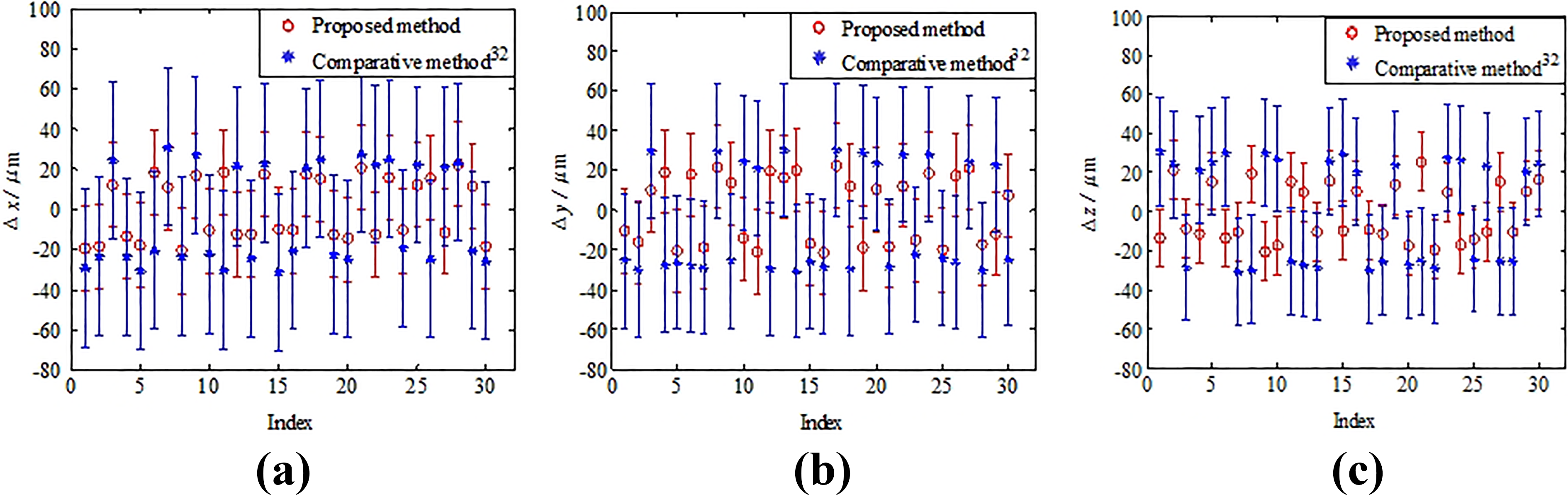
Position alignment errors and the standard deviations of the 30 grasping comparative experiments. (a) Position alignment errors and the standard deviations along axis XE. (b) Position alignment errors and the standard deviations along axis YE. (c) Position alignment errors and the standard deviations along axis ZE.
Assembly experiments
Aligning stage experiments
In aligning stage for assembly, the desired distance for position alignment is set
In one aligning experiment for assembly, the captured images of two components by microscopic cameras before and after alignment are shown in Figure 14. The position alignment error and orientation alignment error are shown in Figure 15. Figure 15(a) shows the position alignment error, while Figure 15(b) shows the orientation alignment error. From Figure 15, it can be seen that the position and orientation alignment errors reduce stably with only nine steps. After the aligning stage for assembly, the position and orientation alignment errors reach

The images captured by microscopic cameras before and after pose alignment. (a) Image captured by camera 1 before alignment. (b) Image captured by camera 2 before alignment. (c) Image captured by camera 1 after alignment. (d) Image captured by camera 2 after alignment.

Position and orientation alignment errors in aligning stage for assembly. (a) The position alignment error. (b) The orientation alignment error.
Series of comparison experiments are conducted with the decoupled orientation and position alignment method in Liu et al.
19
for assembly. The parameters of the controller in the comparative method are the same with the proposed algorithm. The position offset compensation is introduced into the comparative method in Liu et al.
19
to avoid alignment failure. After aligning for assembly, the standard deviation of position and orientation errors with the proposed method are
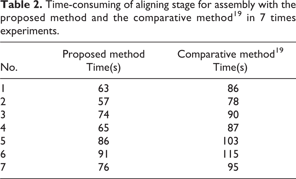
The time-consuming of aligning experiments for assembly with different initial pose errors are listed in Table 2. From Table 2, we can see that the method in Liu et al. 19 requires more time than the proposed control strategy. Based on the robot assembly platform and proposed alignment method, the position and orientation alignments can be achieved simultaneously. Therefore, the proposed pose alignment method has high efficiency.
Time-consuming of aligning stage for assembly with the proposed method and the comparative method 19 in 7 times experiments.
Inserting stage experiments
In the inserting stage, the parameters of the force-based control law (15) are set
In one inserting experiment, the adjusting curve of robotic end effector and the measured forces are shown in Figure 16. Figure 16(a) shows the adjustment of robotic end effector, while Figure 16(b) shows the contacted forces. From Figure 16, it can be seen that the radial contacted forces FX and FY are controlled within acceptable range, which avoids the damage to components. In addition, the adjustments of robotic end effector are smooth, which ensures the stability of the inserting process.

Position adjustment curve and contacted forces in inserting stage. (a) Adjustment curve of robotic end effector. (b) The contacted forces.
The inserting assembly comparison experiments are conducted with the method in Liu et al. 19 The adjusting curve of robotic end effector and the measured forces are shown in Figure 17(a) and (b). From Figures 16 and 17, it can be seen that the adjusting steps in inserting stage for assembly with the proposed method are 72, and the adjusting steps in inserting stage with the comparative method in Liu et al. 19 are 108. The adjusting steps of the proposed inserting method are less than that of the method in Liu et al. 19 The reason is that the adjusting step length along the axes XE and YE are constants in method in Liu et al. 19 While the adjusting step length of the proposed method along the axes XE and YE are computed based on the forces FX and FY. Compared to the constant step length, the proposed assembly method is more efficient.

Position adjustment curve and contacted forces in inserting stage with method. 19 (a) Adjustment curve of robotic end effector. (b) The contacted forces.
Conclusion
An automatic robot assembly system with an industrial robot is established to assemble small components. The designed robot assembly system solves the problem of limited working space for grasping and reduces the complexity of assembly manipulation in the semi-automatic precision assembly with multiple manipulators. The assembly system uses an industrial robot, which improves the efficiency and practicality of assembly as well as lays the foundation for batch assembly in industrial. The proposed “aligning–approaching–grasping” grasping control method can be adapted to grasp other irregular components by replacing the gripper, which is very helpful to eye-in-hand grasping. The proposed “aligning–inserting” assembly control scheme can be used to assemble macroscale/mesoscale or microscale parts with high efficiency. In addition, in aligning stage for assembly, the proposed position offset compensation strategy avoids the grasped component moving out of the microscopic cameras’ field of view. Experiments verify the feasibility and high efficiency of the robot assembly system.
The efficiency of inserting stage for assembly is still lower due to the designed step length along axis ZE, and the alignment accuracy of assembly system need be improved. In the future, we will focus on optimal control methodology to further improve the efficiency of assembly system. Besides, by installing high precision motion stage on robotic end effector to improve the accuracy of assembly system.
Footnotes
Declaration of conflicting interests
The author(s) declared no potential conflicts of interest with respect to the research, authorship, and/or publication of this article.
Funding
The author(s) disclosed receipt of the following financial support for the research, authorship, and/or publication of this article: This work was supported in part by the Science Challenge Project under grant TZ2018006-0204, and the National Natural Science Foundation of China under grants 61733004, 61873266, 61703398, and 61803354.