
Abstract
For collecting image high precisely, the application-oriented type synthesis and kinematics analysis for parallel vehicle-based stabilized platform are systematically carried out. Firstly, taking multi-camera install center and vehicle trajectory offset as research objects, the influence of external perturbation on visual system is analyzed quantitatively by numerical calculation and field testing. On this basis, a new type of 2SPR/RPS parallel mechanism with two-translational and one-rotational degree of freedoms is presented. Secondly, by analyzing the motion characteristic of 2SPR/RPS parallel mechanism, the motion adjoint transformation and input–output mapping for parallel vehicle-based stabilized platform are proposed by screw description of rigid-body movement. In addition, an experimental prototype is developed, and the results between numerical examples and semi-physical simulations are compared in order to prove the validity of theoretical analysis. Finally, based on the concept of influence of external perturbations on tunnel detecting system, an external parameter identify method for coupling pose and object distance of visual system is studied. The results can be extended to development, application, and performance evaluation for parallel vehicle-based stabilized platform in next step.
Introduction
The traditional tunnel detection methods are generally implemented with artificial instruments on the premise of closing roads, which have many deficiencies such as (i) low work efficiency, (ii) high risk, and (iii) low detection precision. 1,2 Based on the advantages of high speed, low undetected rate, high precision, and easy to realize data management, the rapid detection method has become a research focus in transportation equipment development. 3 –6 In recent years, researchers have begun to study intelligent detection method for expressway tunnel based on computer-vision technology. 7,8 Our development team developed a set of tunnel intelligent detection system which can complete detecting tunnel disease at a speed of 80 km/h, as shown in Figure 1. 9 However, due to the complex working environment of expressway tunnels, the tunnel intelligent detection system still have imperative problems such as narrow application range, weak anti-disturbance capability, and low-quality image.

The tunnel intelligent detection system.
Visual system is the core of the tunnel intelligent detection system that is composed by digital camera, laser light source, inertial navigation system, and mechanical device. 10 The perimeter of expressway tunnel section is about 20 m, but the geometrical dimensions of cracks and other diseases are small, generally 0.1–0.8 mm. For this reason, high-quality image acquisition is the precondition to process and identify tunnel disease. 11 –13 However, due to external perturbations such as driver’s subjective consciousness, traffic flow, and road bump, the posture between vehicle-based equipment and tunnel lining will be changed. In particular, the structure parameters of tunnels with different design speed are also various, which seriously affect image acquisition and lead to image blurry or unavailable to image. 14,15 Note that the digital camera of the tunnel detection system has a small depth of field (−200 to +200 mm) and rapidity driving speed (50–80 km/h); it is impossible to isolate the influence of external perturbations on visual acquisition system only by adjusting camera parameters in real time. 16 Therefore, a servo compensation mechanism is needed to realize the relative posture between digital cameras and tunnel lining surface keeping fixed.
The role of stabilized platform is to isolate external perturbations through a set of real-time compensation mechanism and provide a relatively stable environment for devices on plane, ship, and vehicle. 17,18 However, most of the existing stabilized platforms are two-axis or three-axis serial mechanisms, which are mainly used for attitude stability. Parallel mechanisms (PMs) are easy to realize spatial multi-axis compensation, which have advantages such as multi-degree of freedom (DOF) output and large movement range compared to serial mechanisms. 19,20 It is an ideal mechanism model for developing vehicle-based stabilized platform of tunnel visual detection. At present, the configuration of parallel stabilized platforms is mostly Stewart PMs, which need large space occupation and high energy consumption. 21,22 Therefore, it cannot be used in tunnel detection system.
On the other hand, parallel vehicle-based stabilized platform is a multi-rigid-body system in non-inertial frame. Nevertheless, the existing kinematics methods of PMs were analyzed in inertial frame. 23 –25 Traditionally, kinematics relationship between inertial frame and non-inertial frame should be analyzed when investigating rigid-body problems in non-inertial frame. 26,27 Because the traditional description of rigid-body kinematics is described in terms of angular movement and linear movement of a point attached to it, it is more complicate and difficult to obtain a uniform mathematic model when analyzing a multi-rigid-body system, which makes it impossible to research the effects of vehicle perturbation on the performance of PMs. 28,29
A review of the previous works reveals that modern mathematic tools, such as geometric algebra, spatial operator algebra, Grassmann–Cayley algebra, screw algebra, and Lie groups and Lie algebras, have been introduced to rigid-body kinematics analysis. Therefore, compared with other modern mathematical tool, screw theory and Lie groups and Lie algebras were more effective when the number of robot DOFs increases. 30 The pioneering treatise by Hunt laid the foundations for the screw theory, 31 and Duffy and Phillips promoted modern applications of the screw theory. 32,33 With these studies, the elaborate surveys have been contributed to the robot kinematics. 34,35
Focusing on the above, this article is arranged as follows. Second section analyzes the influence of tunnel structure and external perturbation on visual system by numerical calculation and field testing and presents a new type of 2SPR/RPS PM with two-translational and one-rotational DOFs. In third section, based on motion characteristic analysis of 2SPR/RPS PM, the motion adjoint transformation and input–output mapping of parallel vehicle-based stabilized platform are proposed by screw description of rigid-body movement. Furthermore, numerical examples and semi-physical simulations included in fourth section that are performed to validate the mathematical models are presented in this article. Fifth section proposes an external parameter identifies and analysis method for coupling poses and object distance of visual system. Finally, the last section presents conclusions and future works.
Application-oriented type synthesis of parallel vehicle-based stabilized platform
The influence of tunnel structure parameters on visual system
The tunnel image acquisition system is composed of 6 digital cameras and 12 laser lights. The digital camera has parameters of diffusion angle 25°, depth of field 1.5–2.0 m, line frequency 45 kHz, and object distance 3.0 m. A sketch of cross-sectional outline of expressway tunnel is shown in Figure 2, in which H denotes tunnel height, h denotes springing line height, R denotes springing line radius, w denotes lane width, and l and r denote width of left and right removal access, respectively.
36
The frame {o} presents the center line of pavement, x-axis points to tunnel surface, and y-axis is vertical up. For the purpose of collecting image uniformly and completely, the half-range tunnel surface is divided into six parts. The relationship between above segmentation points is shown as follows

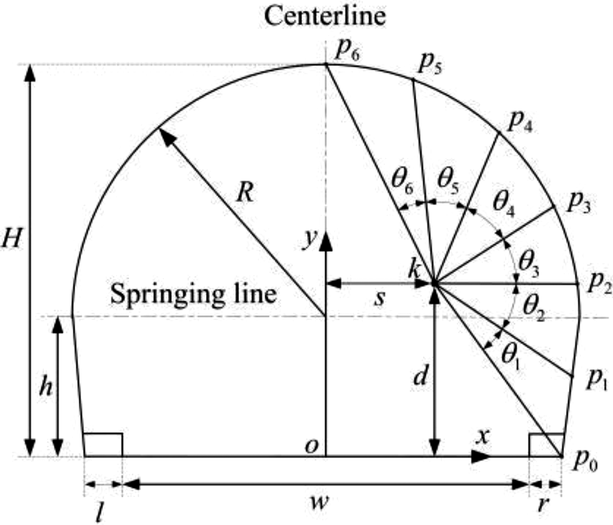
The cross-sectional outline of road tunnel.
where
Let

To ensure the accuracy of image collecting, the range and working distance of each camera should be kept consistent. Meanwhile, the range of camera should be as small as possible. For this reason, a mathematical description of multi-camera install center optimum can be given as

where
From equation (3), the objective function is composed by three single-object functions: (i)

In view of equation (4), the membership degree

where
Substituting equations (3) and (4) into equation (5), the optimal value of multi-camera install center can be obtained as
On this basis, the acquisition range of each camera should be the same to ensure image acquisition quality. Hence, the angle between assembly platform and x-axis of frame {o} can be written as

where
Numerical calculation
Suppose the designed speed of expressway tunnel is 120 km/h, the structure parameters are H = 8.12 m, h = 2.0 m, R = 6.12 m, w = 7.5 m, l = 0.75 m, and r = 1.25 m. 36 According to the lane width, height limitation, and weight limitation of vehicle, the upper and lower bound of variable s and d can be formulated as 0.5 m, 3.5 m and 2.0 m, 4.0 m, respectively.
Suppose s = 1.9 m, the optimal result of single objective function within the scope of variable d can be calculated, as shown in Table 1. The minimum value of various single objective function is
The optimal results of multi-camera install center when s is 1.9 m.


The change curves of membership when s is 1.9 m.
In a similar way, the membership u(s) can be obtained by setting different value s within its scope (0.5–3.5 m). A sketch of global membership surface is shown in Figure 4. It can be seen that the maximum value of membership is 0.85 when the design variable values are s = 2.0 m and d = 3.5 m. In addition, by analyzing surface properties, the design variable d has much bigger effect on membership, but the design variable s, much smaller. On this basis, the angle between assembly platform and x-axis of frame {o} can be obtained as 35.0° by equation (6).

The change surface of global membership.
Similarly, suppose the designed speed of expressway tunnel is 60, 80, and 100 km/h, respectively. The install center parameter of visual system and angle of assembly platform are calculated separately, as shown in Table 2. The variation range of multi-camera install center in different working conditions is Tx: ±0.15 m, Ty: ±0.55 m, and Rz: ±0.5°.
The optimal results of multi-camera install center in different working conditions

The influence of vehicle perturbation posture on visual system
Let
The vehicle trajectory at time t.
In order to obtain experimental data, the field tests are carried out in Zijinshan tunnel of Pingyu highway (4511 m), Hongtiguan tunnel of Changping highway (13,098 m), Hejiabao tunnel of Baomao highway (2004 m), and Luoping tunnel of Fenwu highway (4596 m), respectively. Due to the limitation of space, the experimental data of vehicle trajectory offset in Zijinshan tunnel are introduced, as shown in Figure 6. It can be seen that the variation range of vehicle trajectory offset is Tx: −0.6 to 0.6 m.

The vehicle trajectory offset.
Type synthesis of 1R x 2T yz PM
According to the analysis performed in the previous section, a type of 1R x 2T yz PMs should be synthesized to compensate the effect of external perturbation. According to the PM theory, the constraint screw system of actuated branch has three situations. The constraint screw system should be as less as possible to ensure rotation axis continuous in vehicle-based stabilized platform. Hence, the PMs which have one constraint force and five actuated branches should be synthesized in this article. Based on the concept of mathematics criterion of rigid-body continuous rotation axis, 37 the constraint screw should actually be parallel to each other but not coplanar.
The typical structural form of five-DOF actuated branch is RPS or SPR. For RPS actuated branch, the constraint force expression in terms of frame {o} is

where
Equation ( 7) shows that the constraint force of RPS actuated branch is a space vector which passes through central point of spherical joint (S) and parallel to axis of revolute joint (R). Similarly, for SPR actuated branch, the constraint force expression in terms of frame {o} is

where
Equation (
8) shows that the constraint force of SPR actuated branch is a space vector which passes through central point of spherical joint (S) and parallel to axis of revolute joint (R). Combining with equations (7), (8), and type synthesis principle of vehicle-based stabilized platform, the type of PM is 2SPR/RPS, as shown in Figure 7. The typical structural forms of first and third actuated branches are SPR, the second actuated branch is RPS, and the constraint forces of each actuated branches are

The 2SPR/RPS parallel mechanism.
Coupling kinematics analysis of parallel vehicle-based stabilized platform
Motion characteristic
Combining with equations (7) and (8), the constraint screws of moving platform in terms of frame {o} can be described as

where
Equation (
9) shows that the constraint screws of moving platform are linear independence with each other. Hence, the independent DOFs of mechanism are three. Based on the concept of mathematics criterion of rigid-body continuous rotation axis, the continuous rotation axis is a space straight line which is parallel to constraint force vector or intersect on constraint point, and the movement tracking information is a space straight line which perpendicular to all constraint force vector. The constraint force vector of 2SPR/RPS,
The similar kinematics characteristic can be obtained by using above analysis method when the 2SPR/RPS PM at any poses in workspace. Over all, the vehicle-based stabilized platform based on the 2SPR/RPS PM can isolate external perturbation such as sway, heave, and roll, which can provide a relatively stable work environment for visual system.
Motion adjoint transformation
For the convenience of the reader, a sketch of stabilized platform frames is given in Figure 8; the frames can be described as follows.

The coordinate system of vehicle-based stabilized platform.
(1) Inertial frame {e}: the origin is coincident with the center of vehicle, xe -axis points to the direction of vehicle running, and ze -axis is vertical up. (2) Vehicle frame {v}: the origin is coincident with the center of vehicle; the axes are parallel to frame {e} when vehicle is in balance. (3) Fixed platform frame {o}: the origin is on the center of fixed platform, xo -axis points to the running direction, yo -axis points to tunnel surface, and zo -axis is vertical up. (4) Moving platform frame {p}: the origin is on the center of moving platform, in which axes are parallel to the corresponding axis of frame {o} when the mechanism is in initial posture.
The configuration matrix of moving platform with respect to frame {o} is
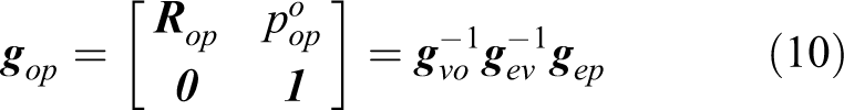
where
Based on the multi-rigid-body acceleration adjoint transformation, the rigid-body velocity and acceleration of moving platform relative to frame {o} in terms of frame {e} can be described as

where

Furthermore, the configuration matrix of non-inertial frame {o} relative to inertial frame {e} is

Substituting equation (11) into equation (12), the velocity adjoint transformation of moving platform and stabilized platform is given as

where
Similarly, the acceleration adjoint transformation of moving platform and stabilized platform can be given as

where 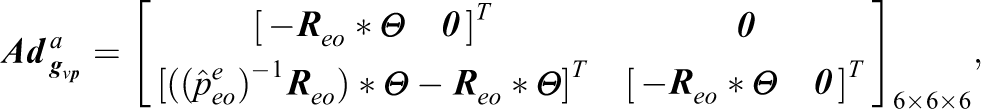
Motion input-output mapping
Let

According to the screw theory, the motion joint screw of actuated branch in terms of frame {o} can be described as

where
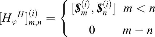
Extracting corresponding parts of the above equation, the velocity and acceleration mapping of moving platform to actuated branches can be established as

where
Combining with equations (13) and (16), the velocity input–output mapping of vehicle-based stabilized platform can be established as

where
Combining with equations (14) and (16), the input acceleration expression of actuated branches is

where
By further simplifying and rearranging the above equations, the acceleration input–output mapping of vehicle-based stabilized platform can be established as

where
Semi-physical simulation of parallel vehicle-based stabilized platform
System parameters
Taking the developed tunnel detection system as research object, the 2SPR/RPS PM has the dimensions of moving platform d 1 = 1600 mm, fixed platform d 2 = 1800 mm, and initial height h = 1200 mm.
For simplicity, the inertial movement of vehicle can be simulated using sine wave superposition. Hence, the motion laws of sway, heave, and roll can be given as

where
For kinematics analyzing of parallel vehicle-based stabilized platform, the motion laws of moving platform can be assumed as sinusoidal waveform. In view of the demands of digital camera for environment-stability performance, the amplitudes and periods of moving platform with respect to inertial frame are
System simulation
Based on the motion adjoint transformation and input–output mapping of vehicle-based stabilized platform, a theoretic calculation of displacement, velocity, and acceleration of actuated branches is given in Figure 9. Note that the main source of stabilized platform is vehicle’s perturbation; the curves of each actuated branches are nearly the same; and the angle, velocity, and moment of motor will be peaked at the same time. From the graphs, it can be seen that the maximum input displacement, velocity, and acceleration of actuated branches are 0.85 m, 0.95 m/s, and 1.5 m/s 2 , respectively.

The calculation results of actuated branches. (a) Displacement, (b) velocity, and (c) acceleration.
Based on the obtained results from this article, our team developed a set of 2SPR/RPS PM prototype. Meanwhile, the vehicle-based stabilized platform is a multi-rigid-body system in non-inertial system, but the prototype is in inertial system. In order to verify the correctness of the theoretical analysis presented in this article, a semi-physical simulation model is built in Figure 10, which consists of simulation program and experimental prototype. The role of simulation program is to provide simulation signal for external perturbation of vehicle and movement of moving platform. Then the displacement, velocity, and acceleration of moving platform relative to inertial system can be obtained by equations (10), (13), and (14), respectively, and the displacement, velocity, and acceleration can be further calculated by equations (15), (17), and (18), respectively. Meanwhile, a detection branch is installed among actuated branches to obtain posture of moving platform.

The semi-physical simulation model.
On this basis, experimental prototype can be moved by control signal; the corresponding motion curves of each actuated branch can be given by TRIO controller, as shown in Figure 11. From the graphs, it can be seen that the simulation curves of displacement, velocity, and acceleration are fully consistent with theoretic calculation, which shows the high accuracy and efficiency of kinematics modeling method presented in this article.

The simulation results of actuated branches. (a) Displacement, (b) velocity, and (c) acceleration.
External parameters identity and analysis of vision system
Coupling posture identity and analysis of digital camera
A sketch of vision system frame is given in Figure 12. The frames can be described as follows: (1) inertial frame {e}: the origin is coincident with the install center k of multi-camera. xe
-axis is within the install plane of camera, horizontally pointing to tunnel surface; ye
-axis is vertical up; and ze
-axis points to the direction of vehicle running. (2) Installation frame {k}: xk
- and yk
-axes are within the install plane of cameras and along horizontal and vertical direction, respectively; zk
-axis is perpendicular to the install plane of cameras. (3) Camera frame

The diagram of coordinate system.
When vehicle in quiescent state, the initial pose matrix and position vector of frame
Let
Based on the concept of multi-rigid-body transformation, the configuration matrix of digital camera with respect to frame {e} can be given as

where

Combining with equation (19), the coupling pose of digital camera at any time can be established as
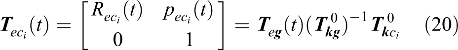
The above equation establishes the digital camera coupling pose parameters disturbed by vehicle; the coupling rotation and translation are
Object distance modeling and analysis of digital camera
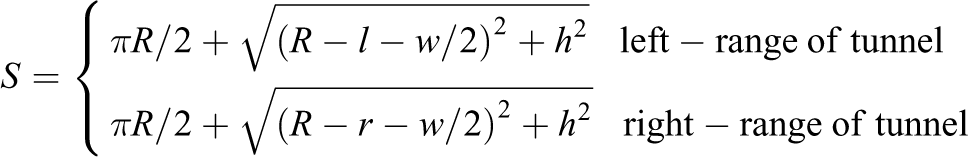
In Figure 12, the dashed part is the sample curve of scanner at time t; the data format is
The position vector of each sample point with respect to the scanner frame {s} is

where

Therefore, the position vector of each sample point
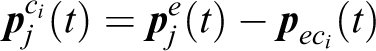
where

Conclusion and future works
The sway, heave, and roll caused by external perturbation of vehicle severely affect vision system. Numerical calculation and field testing show the variation ranges are Tx: ±0.6 m, Ty: ±0.55 m, Rz: ±0.5°. Based on this, a new type of 2SPR/RPS PM has been synthesized. The motion adjoint transformation and input–output mapping between external perturbation and mechanism movement are built. In addition, an experimental prototype is developed, and the correctness of theoretical analysis is verified by semi-physical simulation. On this basis, the mathematical expressions of coupling posture and object distances of visual system are proposed. It can provide evidence for digital image correcting and geometric measuring in next step.
In the near future, the control strategy of 2SPR/RPS PM prototype will be solved by kinematics mapping relationship, and the compensation ability evaluation index of stabilized platform will be studied. On this basis, we should focus on time-delay estimation method to realize high-accuracy stabilization for vehicle-based stabilized platform. Meanwhile, the image-processing systems of tunnel detection vehicle will be optimized by the mathematical expressions of coupling posture and object distances of visual system presented in this article, and the measuring modeling between disease geometry and object distance will be developed.
Footnotes
Acknowledgements
The authors sincerely thank to Professor Tieshi Zhao of Yanshan University for his critical discussion of PM type synthesis and Professor Qingyong Li of Beijing Jiaotong University for his critical discussion of machine vision.
Declaration of conflicting interests
The author(s) declared no potential conflicts of interest with respect to the research, authorship, and/or publication of this article.
Funding
The author(s) disclosed receipt of the following financial support for the research, authorship, and/or publication of this article: This work was supported by National Natural Science Foundation of China (grant no 51705229) and the National Natural Science Foundation of Shanxi Province (grant no 2017-1-25).