
Abstract
This article proposes a control strategy that combines the double power reaching law with the modified terminal sliding mode for tracking tasks of rigid robotic manipulators quickly and accurately. As a significant novelty, double power reaching law can reach the sliding surface in finite time when the system is in any initial state. At the same time, modified terminal sliding surface guarantees the system that position and velocity error converge to be zero approximately. In other words, the control law is able to make the system slip to the equilibrium point in a finite time and improves the speed of the system approaching and sliding modes. The simulation results demonstrate the practical implementation of the control strategy, verify its robustness of more accurate tracking and faster disturbance rejection, and weaken the chattering phenomenon more effectively compared with the conventional terminal sliding mode controller.
Introduction
Manipulator is a kind of complex system with strong coupling and nonlinearity. At the same time, there are some uncertain factors, such as modeling error and external disturbance, when the mathematical model is set up in actual working conditions. The sliding mode variable structure control strategy is mainly embodied in the variable structure. In a dynamic process, the system is forced to slide in accordance with the specified state, depending on the current state of the manipulator system. In fact, the design of the sliding mode variable structure control law has little effect on the variation of parameters and disturbance performance of random occurrence of the manipulator system that is not so sensitive and suited for the strong nonlinear manipulator system. Sliding mode control (SMC) is a systematic and effective approach to robust control that maintains the system stability and consistent performance in the presence of modeling uncertainties and disturbances. SMC has been successfully applied to a lot of mechatronic systems, permanent magnet synchronous motor, 1,2 steer-by-wire system on vehicles, 3,4 and robotic hands 5,6 ; however, there still exist some obstacles, such as noncontinuous switching inputs in high frequency and low convergence speed of the tracking errors. 7,8 To achieve a fast convergence in the sliding phase, the terminal sliding mode (TSM) control is developed based on the finite time control theory 9 and compared with the SMC design mentioned above, and the most significant contributions of the TSM concept involve introducing the finite time convergence to the sliding phase to complete the global finite time convergence. 6,10 –12 Hong 13 studied the application of SMC in mobile robot and put forward a new double power reaching law (DPRL) that has achieved good control effect. In the literature, 13,14 the SMC method based on DPRL is applied to the manipulator system, and stability of the system is proved in finite time. A new TSM surface is proposed and compared with the traditional terminal sliding mode surface. 15 The time expression of the system reaching the sliding surface is obtained by the DPRL in any initial state. 16,17 At the same time, it is also necessary to determine the finite time according to the specific parameter of the reaching law. The purpose of trajectory tracking of manipulator is to control state variables such as position and velocity of joints of the manipulator according to the control input torque of each joint so that it can accurately track the given trajectory. 18 –21
On the basis of the present research, a control strategy combining the DPRL and the modified terminal sliding mode (MTSM) surface is proposed. The tracking control effect of the manipulator is obvious, and the chattering phenomenon of the manipulator is reduced effectively.
Dynamic model description of manipulator
The dynamic model of manipulator is established according to Lagrange formula method 22 and two degree-of-freedom (DOF) manipulator is taken as the controlled object in plane. Therefore, the dynamic equation of the standard 2-DOF manipulator is as follows

The matrix before the state variable is
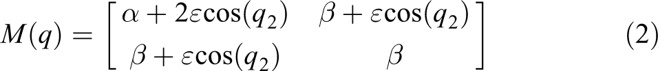


where
In actual engineering, it is very difficult to establish a precise mathematical model of manipulator, and there are many uncertain factors that interfere with the accuracy of modeling. It should make reasonable approximations and trade-offs when we establish the mathematical model of manipulator regularization. So some uncertain factors should be abandoned according to the actual situation. The actual uncertainties include parametric uncertainty, nonparametric uncertainty, and the unknown interference of the external environment in the actual working condition. These uncertain factors may make the entire control system unstable, and the actual dynamic model of the manipulator should also include error in modeling parameter change. These uncertain factors are usually regarded as external disturbances


where
Approach law and sliding surface design
Analysis and design of reaching law
The traditional power reaching law (PRL) is

where
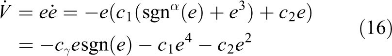
Consider the Lyapunov function (1) when

It is proved that the DPRL can reach the sliding surface and keeps asymptotically stable at
(2) when
Proof of limited time
The manipulator system can reach the sliding surface at any position other than the sliding surface in a limited time

where
In fact, according to the above description, the manipulator system can be divided into two parts at the time of reaching the sliding surface: (1) The manipulator system starts from the initial state (2) The time of the mechanical arm system from the initial state


By the nature of definite integral

It can be proved that the manipulator system reaches the sliding mode surface in any position far away from the sliding surface

According to the actual situation of considering physical problems, the first item to the right of the formula (7) will be in the lead when the initial state of the manipulator system is at
Analysis and design of sliding surface
The tracking error of joint angle position of the manipulator is defined as

where qd is the desired joint angle position of the manipulator and q is the actual joint angle position of the manipulator.
The traditional TSM is

where
For the stability analysis, there is
Consider the Lyapunov function
where
when when
It is shown that the manipulator system is asymptotically stable in the sense of Lyapunov from the Lyapunov stability criterion.
Proof of limited time
The sliding surface can be divided into two parts according to the size of the joint angle position error when the manipulator system slides to the sliding surface
(1) When

The joint angle position error of the manipulator is larger at this stage. The sliding surface is

The differential equation is solved by Bernoulli method according to the concrete form of formula (18). It is possible to calculate the time

(2) When

The joint angle position error of the manipulator is less at this stage. The sliding surface is

In the same way, Bernoulli method is used to solve the differential equation of formula (21). It is possible to calculate the time for the manipulator system from the intermediate state

The sliding surface of formula (15) has been cut at different stages appropriately in calculating the time that the manipulator system slides from the sliding surface

Document calculates that the system slides to the system equilibrium in an arbitrary initial state in a limited time through terminal sliding surface, but reaching law is not considered. It is mainly divided into the approaching mode and the sliding mode when calculating the mechanical arm system that reaches the system equilibrium at any initial state. It is proved that the system can reach the equilibrium point in a limited time

Sliding mode variable structure control law design
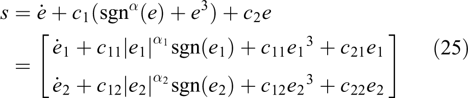
Design of sliding surface can be obtained by formula (8)
Combine dynamic model of manipulator of formula (6) with MTSM, there is

Therefore, the control law of the manipulator system can be obtained by combining the DPRL of formula (7) and the modified terminal sliding surface of formula (15), as shown in the following equation

Comparison and analysis of simulation results
Two-joint rigid manipulator with the load is used as the controlled object for simulation experiment from the manipulator model in the literature,
23
–25
as shown in Figure 1. The manipulator quality of the first joint is

The physical structure of two joint rigid manipulator with load.
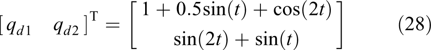
The given position instruction of the two joints of the manipulator system is
The given initial state of the manipulator system is

The given external disturbance of the manipulator system is

Unfortunately, there is no way to design the controller parameters. We have determined the control parameters in the design of the manipulator control law as follows through a large number of simulation experiments.
Build the SMULINK module in MATLAB and finish the system function according to the manipulator control law. The simulation frequency of the manipulator is 0.01 s. The simulation results are shown in Figures 2 to 5.

(a) Position and (b) speed tracking curve of joint 1.

(a) Position and (b) speed tracking curve of joint 2.

Phase trajectory of (a) joint 1 and (b) joint 2.

Control inputs for (a) joint 1 and (b) joint 2.
It can be seen that the manipulator control law by the MTSM based on the DPRL tracks the position and velocity of the manipulator joint 1 and joint 2 according to the given position and speed instructions of the manipulator as shown in Figures 2 to 5 effectively.
The joint 1 can track the given position instructions at 1.95 s accurately, and the tracking error tends to zero in Figure 2. However, there is a certain error in speed tracking, and the accuracy decreases when the speed is tracked between 5.2 s and 5.4 s. Similarly, position and speed tracking effects of joint 2 are the same as joint 1 approximately, as shown in Figure 3. It shows that the position tracking is more accurate than the speed tracking in the trajectory tracking of the manipulator.
The speed error is also decreasing with a decrease in the position error of the manipulator as shown in Figure 4. The intense vibration makes the manipulator system reach a balance point near the equilibrium point eventually and the tracking error of position and velocity tends to zero.
The manipulator system is not robust when the system does not enter the sliding mode in fact and the system may not have robust stability with the change of some parameters or the external disturbance of the system, and so on. The chattering phenomenon of the control input torque in the manipulator system is caused by the discontinuous switching characteristic of the sliding mode variable structure control in Figure 5. The control input torque of the manipulator system is larger in the initial state, but it is kept within a certain range ultimately. The control input torque of the first joint of the manipulator is kept between 100 N·m and 100 N·m, and the control input torque of the second joint of the manipulator is kept between 50 N·m and 50 N·m.
In this article, different loads of the manipulator are also simulated, and the change of control parameters is not obvious. For example, the load with 1, 1.5, and 2 kg and the control parameters with different weights are listed in Table 1.
Comparison control parameters of different loads.

Comparison and analysis of Symbolic function and Saturation function
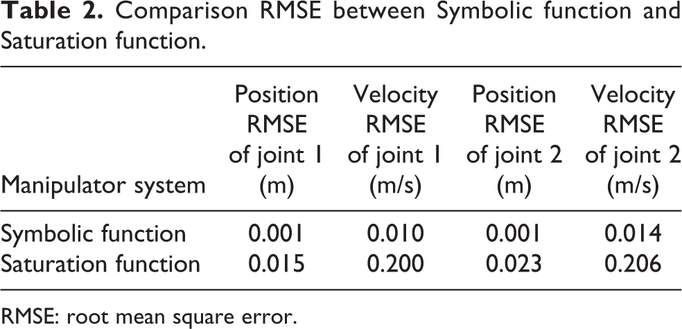
The discontinuous Symbolic function (sgn) of the control law of formula (27) is changed into a continuous hyperbolic tangent function Saturation function (tanh) in order to reduce the mechanical arm system chattering effectively. The simulation results are shown in Figures 6 to 8 and the comparison of tracking root mean square error (RMSE) is listed in Table 2
Position and velocity error of (a and b) joint 1 and (c and d) joint 2. Control inputs for (a) joint 1 and (b) joint 2. Phase trajectory of (a) joint 1 and (b) joint 2. Comparison RMSE between Symbolic function and Saturation function. RMSE: root mean square error.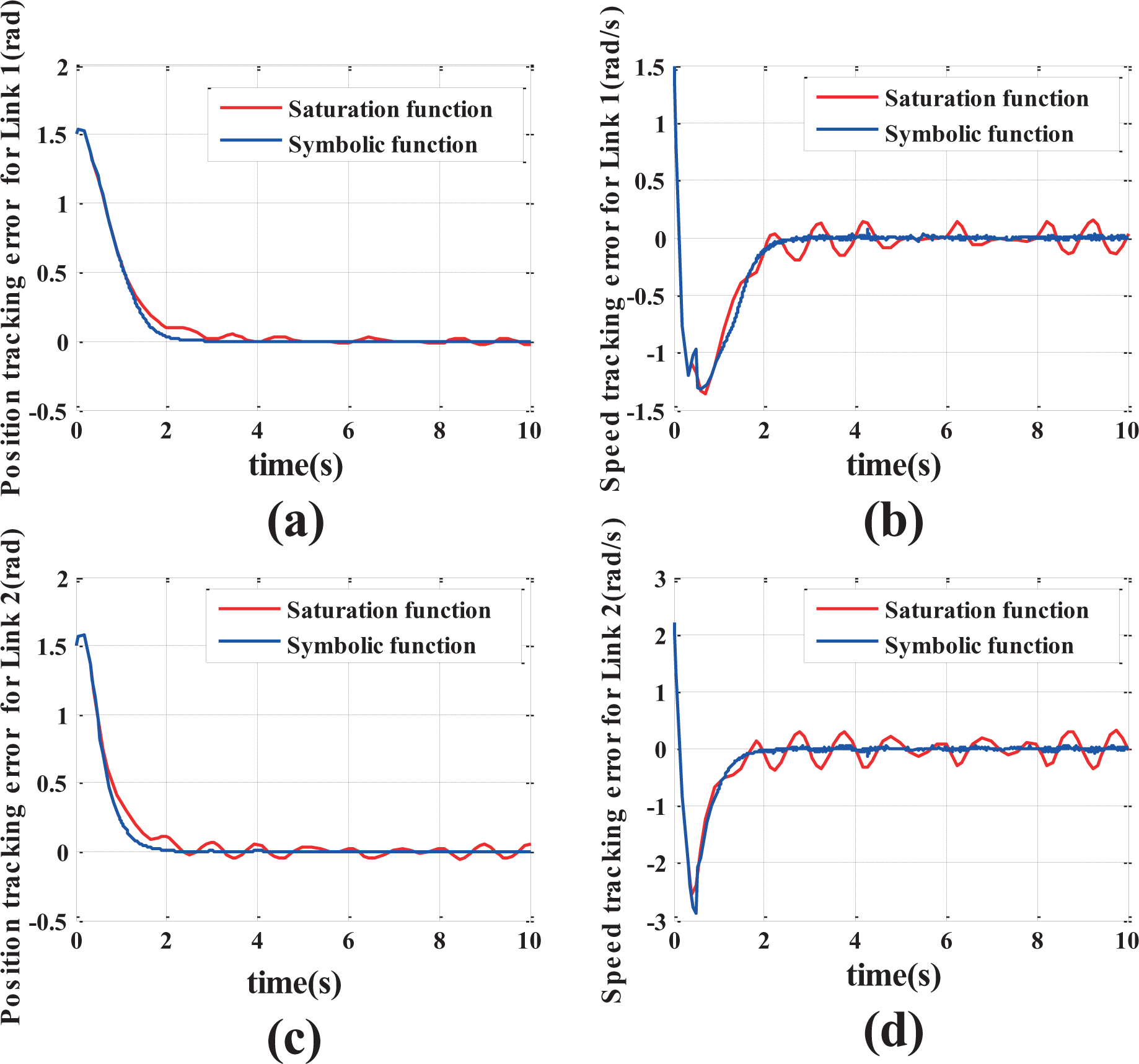


It can be seen that the position and velocity tracking error of the manipulator are increased about 0.03 m and 0.05m/s when the signed function sgn of the formula (27) is changed into a Saturation function tanh obviously in Figure 6. The increase in speed tracking error is most obvious especially. The convergence performance of the tracking error and the capacity of resisting disturbance are weakened greatly after the Saturation function is used.
Although the chattering phenomenon of the mechanical arm system is improved obviously, the chattering is weakened effectively as shown in Figure 7. In fact the Symbolic function sgn is changed into Saturation function
The speed tracking error is also decreasing as the position tracking error of the system decreases gradually but a stable limit cycle ((0.01,0), r = 0.01) is formed and self-excited oscillation is generated when the system moves near the equilibrium point in Figure 8. Even through the Saturation function will restrain the chattering phenomenon of the manipulator effectively, the system vibration amplitude will not increase as a result of the saturation characteristics of the system indefinitely. It will remain stable when it reaches a certain level.
It can be seen that Saturation function sacrificed the tracking accuracy and stability of the manipulator to reduce no obvious chatting phenomena of the manipulator. Therefore, it is not advisable to change Symbolic function into Saturation function.
Comparison and analysis of MTSM and TSM
The MTSM is changed into the TSM. The simulation results are shown in Figures 9 and 10, and the comparison of tracking RMSE is presented in Table 3.

The position and velocity error of (a and b) joint 1 and (c and d) joint 2 based on a different terminal sliding surface.

Control inputs for (a) joint 1 and (b) joint 2 based on the conventional terminal sliding surface.
Comparison RMSE between TSM and MTSM.

RMSE: root mean square error; TSM: terminal sliding mode; MTSM: modified terminal sliding mode.
The change in position and speed error of the manipulator system are not obvious, but the chattering phenomenon of the manipulator system is more pronounced in Figure 10 by comparing Figures 10 and 5. The manipulator system has good robustness and robust stability by adopting the control law that is designed by MTSM. It can also reduce the chattering phenomenon of the manipulator after satisfying the precision index of trajectory tracking and verify the superiority of MTSM.
Comparison and analysis of PRL and DPRL
The DPRL is changed to the traditional PRL, and the simulation results are shown in Figures 11 and 12 and the comparison of tracking RMSE is shown in Table 4.
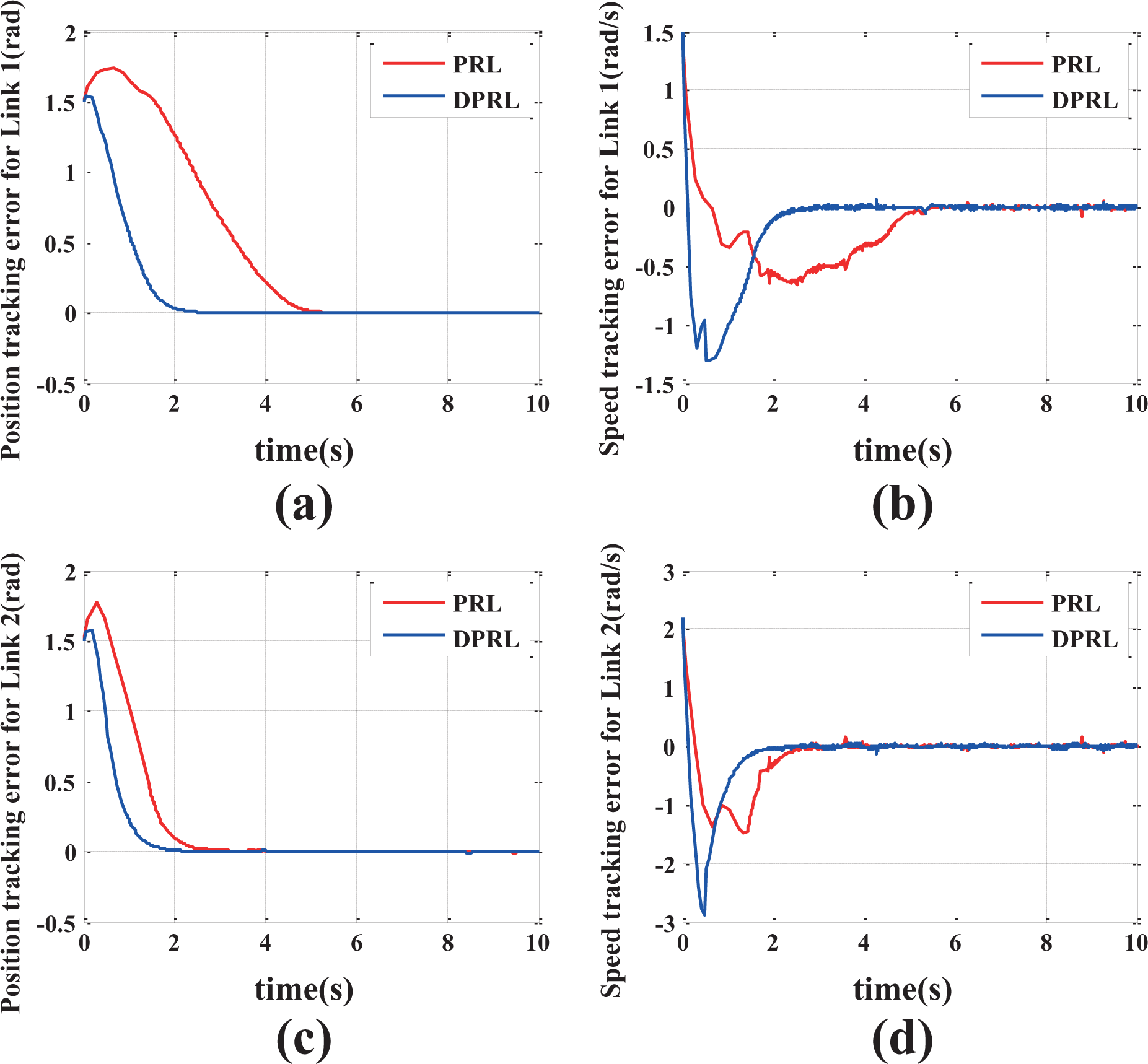
Position and velocity error of (a) joint 1 and (b) joint 2 based on a different approach laws.

Position and velocity error of (a and b) joint 1 and (c and d) joint 2 based on different approach laws.
Comparison RMSE between PRL and DPRL.
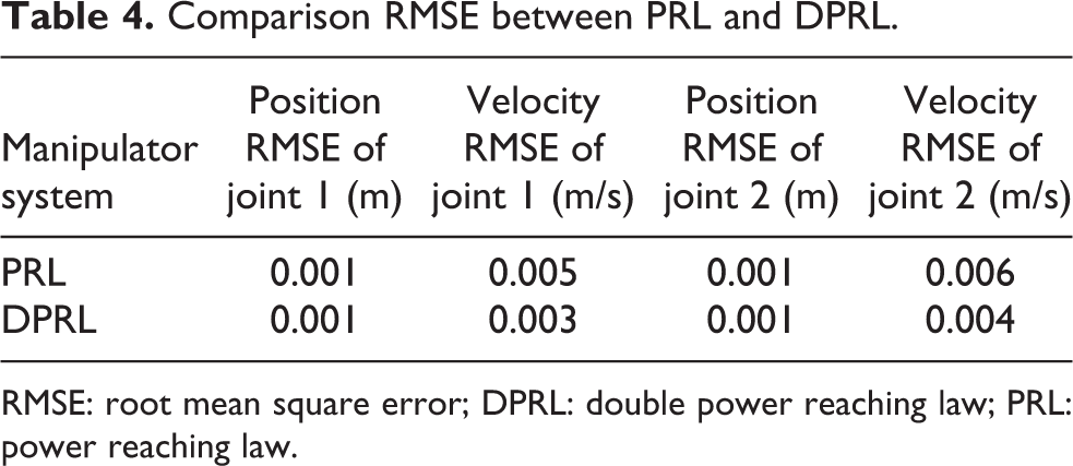
RMSE: root mean square error; DPRL: double power reaching law; PRL: power reaching law.
The system is able to reach the sliding surface far away from the sliding surface
Although the manipulator system reaches the equilibrium point quickly, it is at the expense of the control input torque of the manipulator. However, the larger control input torque is only instantaneous and tends to steady state immediately. At the same time, the torque generated is also within the controllable range. It has no influence on the manipulator control system. Therefore, the overall revenue is obvious, and the DPRL is more prominent than the PRL.
Conclusion
It can be obtained that a control strategy combining the DPRL with the MTSM is adopted to make the manipulator system track the given target trajectory effectively by comparing the PRL and the DPRL, Symbolic function and Saturation function, and TSM and MTSM. The approach and the sliding speed of the system are improved on the premise that the chattering phenomenon of the manipulator is weakened obviously in a finite time. The simulation results show that the control strategy can weaken the chattering phenomenon of the manipulator and have high tracking precision, fast convergence rate, strong robust stability, and capacity of resisting disturbance. However, the control parameters selection is still a challenge, especially in the control scheme. Therefore, the author believes that we will do the best possible use of artificial intelligence to adjust the appropriate parameters in the future.
Footnotes
Declaration of conflicting interests
The author(s) declared no potential conflicts of interest with respect to the research, authorship, and/or publication of this article.
Funding
The author(s) disclosed receipt of the following financial support for the research, authorship, and/or publication of this article: This work was partially supported by the National Natural Science Foundation of China [Grant No. 51475115], Shandong province science and technology innovation project (2018CXG0905 and 2018GGX101034), University Co-construction Project at Weihai (ITDAZMZ001708) and the Fundamental Research Funds for the Central Universities [Grant No. HIT.NSRIF.2016106].