
Abstract
In recent years, there has been a growing number of studies in spherical parallel mechanisms, particularly synthesis, kinematics, and work area singularities. The interaction of degrees of freedom and geometry leads to the nonlinear phenomena, in the dynamics of mechanism. There are few studies into the dynamic properties of such mechanisms. This article deals with the dynamic property of the parallel spherical manipulators, with three degrees of freedom, and presents determination of acceleration input links, oscillations, and the problem of control. Algorithm of control is based on the concept of minimized coordinates, velocities, and acceleration using inverse dynamic problems. This allows synthesis of this algorithm, which can realize a motion in accordance with prescribed trajectories. Finally, the results of calculations are defined.
Keywords
Introduction
Parallel manipulators consist of a mobile platform that is connected to a fixed base by several limbs in parallel. Parallel manipulators are widely applied because of their advantages of high speed and accuracy stiffness). Among the parallel manipulators, spherical manipulators occupy an important role. 1 –7 In a spherical parallel manipulator, the links have pure rotational motion. These manipulators are designed for orienting movements. These manipulators have been the subject of many publications dealing with the structure, the problem of positions and velocities, and some problems with inverse dynamic analysis. However, not all important problems have been addressed. The problem with accelerations and analyzing nonlinear oscillations, are dealt with in this article.
In this article, analysis of accelerations is based on a system of differential equations. This method was used in the study by Gosselin and Angeles 8 for analyzing velocities. For analyzing nonlinear oscillations, nonlinearities conditioned by the geometry of kinematic chains are considered. The feature of these devices was first pointed out by Ganiev and Kononenko. 9 Inertial characteristics of the output link and elastic generalized forces acting in drives of the manipulator are considered.
Besides, the control problem is very important. In the analysis of accelerations, inverse dynamic modeling is carried out, by virtual work principals and the dynamic control method is implemented. Control algorithm is based on the concept of minimized coordinates, velocities, and acceleration.
Nonlinear oscillations
The mechanism contains five rotational pairs in each chain (Figure 1). This allows an increase in the working range for manufacturing operations. In the considered spherical manipulator with five kinematic pairs in each chain, each input link is connected to the motor. Motors are located at the base. The actuators’ axes and final kinematic pairs intersect at the center of Cartesian coordinates. Three intermediate kinematic pairs in each chain is perpendicular to the axis of the actuators. The spherical mechanism can be used in medical instruments, orienting devices, machine tools, and so on. The output link is a platform that revolves around three axes intersecting at the point O. The output coordinates are angles of rotation of the platform α, β, γ around the axes, the relative positions of which are described by a fictitious kinematic chain. The generalized coordinates are angles ϕ 11, ϕ 21, ϕ 31, respectively. The angles of rotation for the input, links the first, second, and third kinematic chains. Each of the three kinematic chains has two hinges with intersecting axes and three hinges with parallel axes.
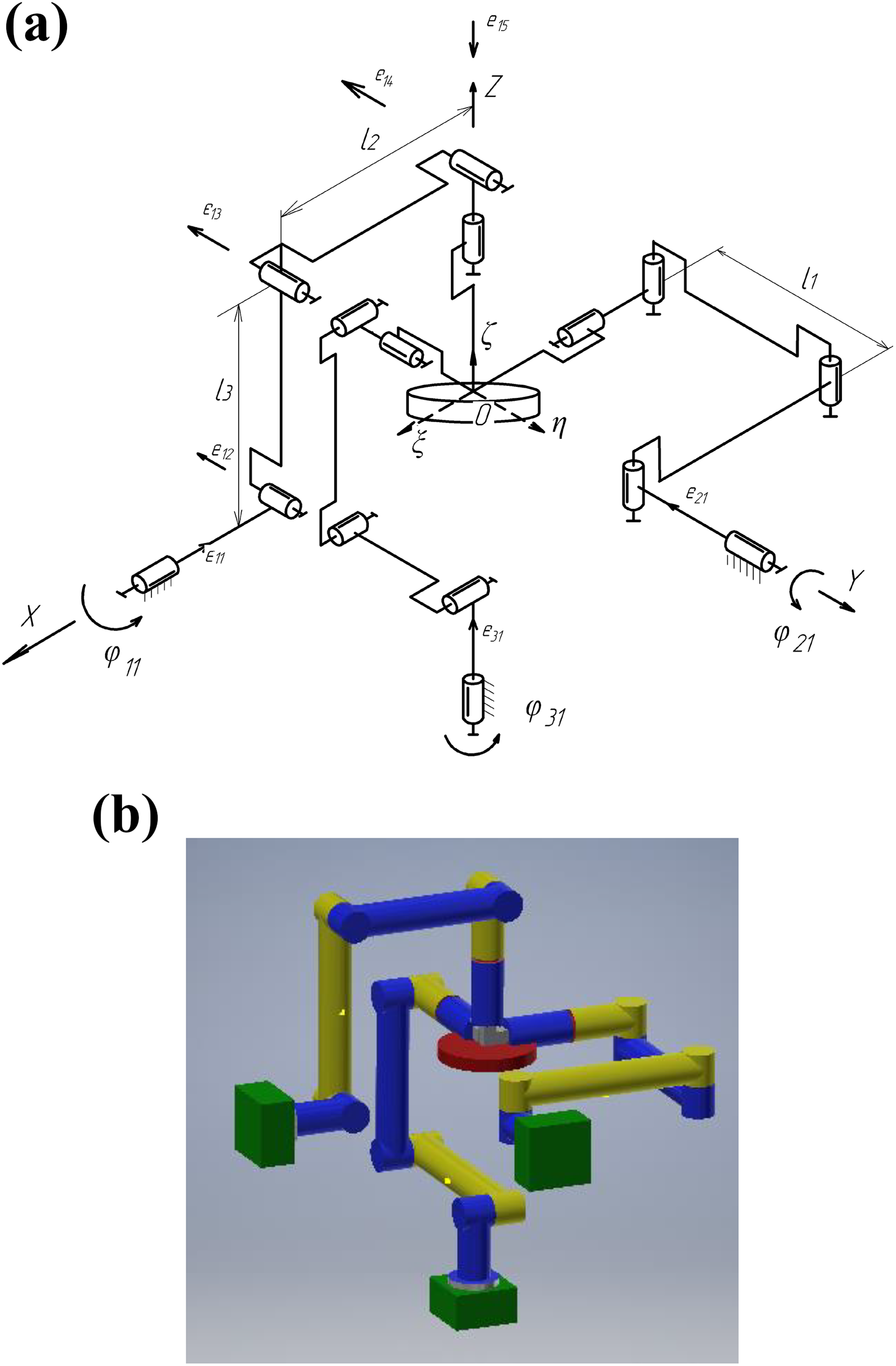
(а) Kinematic scheme and (b) 3-D CAD model spherical manipulator with five kinematic pairs in each chain.
Let us associate the output link of the manipulator with a moving coordinate system ξ, η, ζ whose axes are located on the main central axes of inertia of this link. Let us also note that for zero values of the orientation angles (α = β = γ = 0), the direction of the axes ξ, η, ζ coincide with the directions of the axes x, y, z, respectively.
Furthermore, in this case, one kinematic pair, which is a part of an equivalent spherical manipulator (Figure 2), replaces three rotating pairs ei 2, ei 3, ei 4, consisting of the original manipulator. Let us note that for zero orientation angles, we have the relation ei 1 = ei 5. There are similar relations for the rest of the kinematic chains.

Spherical manipulator with three kinematic pairs in each chain.
Let us consider the problem of accelerations, which may be important in the analysis of the dynamics of the manipulator. The system of equations for a spherical manipulator with three kinematic chains can be represented by the following system of equations 10,11

where F
1, F
2, F
3 are system of kinematic problem equations
Differentiating these expressions with respect to t, we obtain a system of equations that connect the input and output velocity links

Differentiating these expressions for the second time with respect to t, we obtain equations that connect the input and output accelerations links

The nonlinear character of the mechanical system is conditioned by its geometry and interconnected drives. 12 The equation of motion of a spherical manipulator with three degrees of freedom has the following form
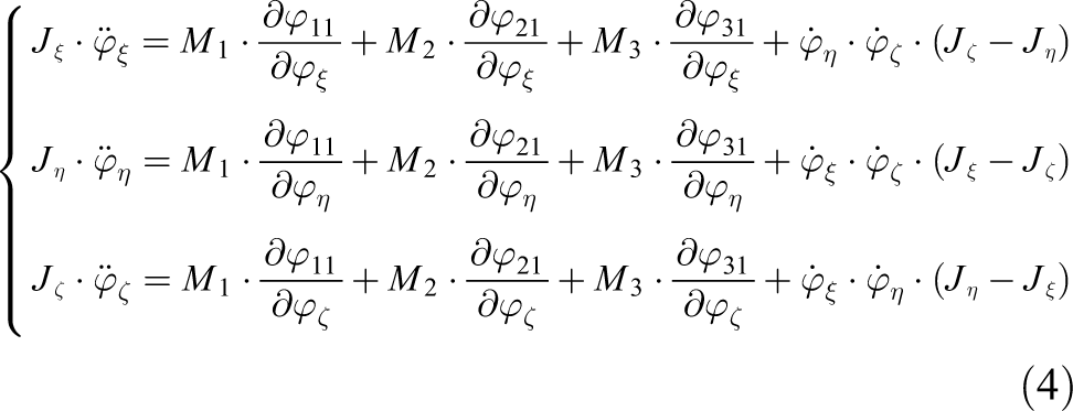
where
The variable coefficients can be determined from the equations of the direct problem of velocities by screw calculus.
13,14
Since the power screw interacts with the unit vectors of the nondriving pairs, then the relative moments mom(

where (xi
1, yi
1, zi
1) are the Plucker coordinates of the unit vectors ei
1 and
The system of equations for three kinematic chains has the following form

where
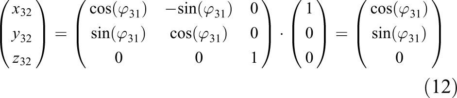
Then the variable coefficients, which stand before the values of the moments M, can be defined as follows


The remaining coefficients have a similar form. The coordinates of the unit vectors of the second (x 12, y 12, z 12) and the third (x 13, y 13, z 13) pairs of the first chain are calculated as follows


where A is the matrix and has the form A = A 3 A 2 A 1, where A 1 is the matrix of rotation around the axis x; A 2 is the matrix of rotation around the axis y; A 3 is the matrix of rotation around the axis z.
For the second chain, the coordinate of the unit vectors of the second and third pairs are


For the third chain, the coordinates of the unit vectors of the second and third pairs are

The coordinates of the unit vectors of the first, second, and third chains in the moving coordinate system is defined by the matrix A −1, which is the inverse of matrix A

The coordinates of the unit vectors of the third pairs of the first, second, and third chains are

To determine the angles α, β, and γ, a ratio between the angular velocities in the moving system of the coordinates
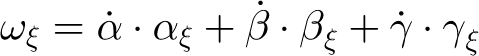


where


The dependence of the angles of rotation of intermediate ϕi 1 is determined by solving the problem of the position 11


The moments in the drives are

Using numerical integration, we find changes in the coordinates of the output link for the following initial conditions: α = 0.3 rad, β = 0 rad, and γ = 0.25 rad. Figure 3 shows the laws of changes in α (a), β (b), and γ (c) for nonlinear oscillations of the output link.
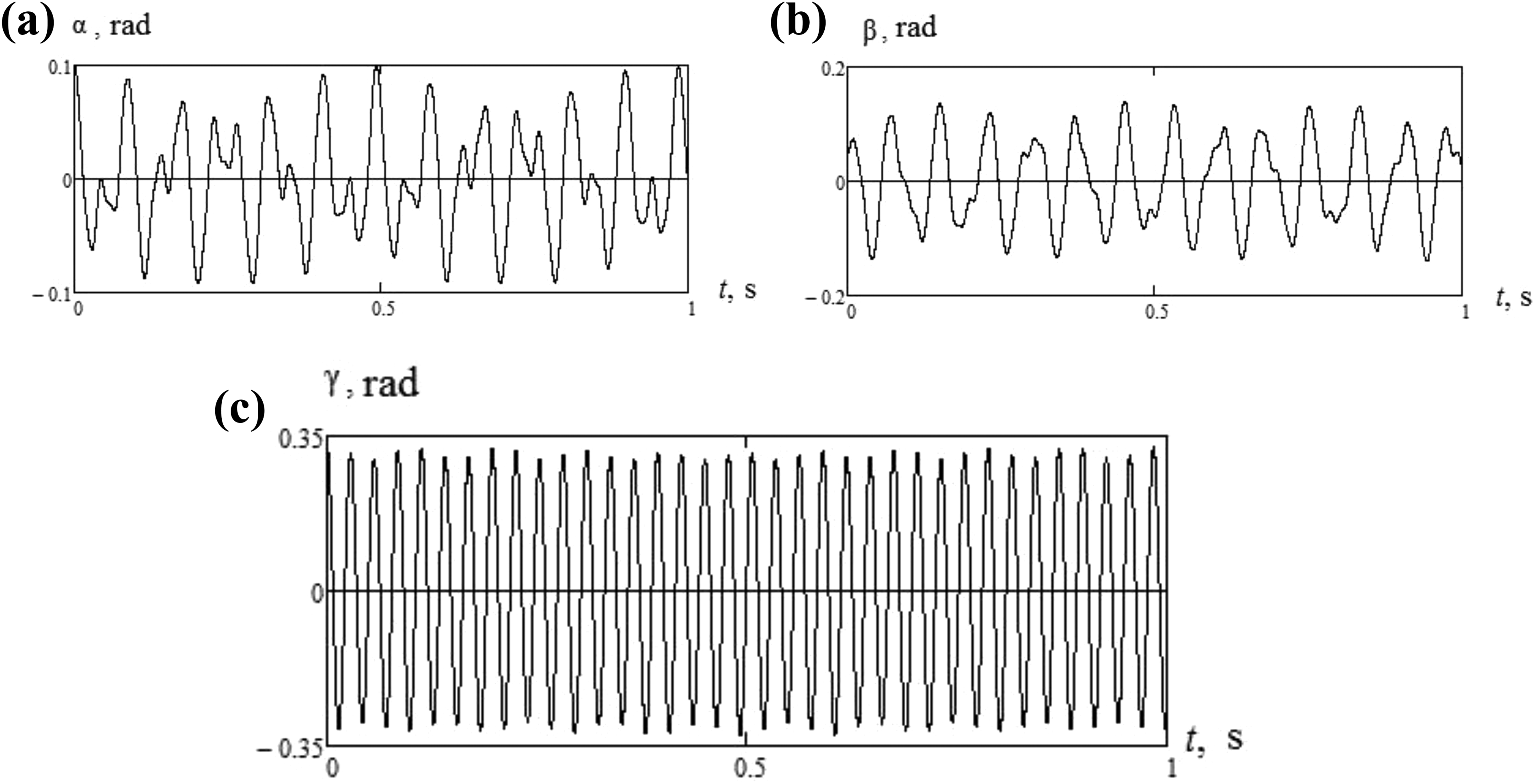
Graphs of coordinate change (a) α, (b) β, and (c) γ.
Control algorithm
Control is one of the important problems. The characteristics of the parallel manipulator is the mutual influence drives. There are different approaches to solve the problems of control. 15 –18 But control of mechanisms is not enough. It presented the various schemes. This applies to kinematic control. The problem of dynamic control was also not enough. We have considered a specific mechanism, which is represented for the first time. Numerical experiment confirmed the theoretical calculation.
Used algorithms are based on the inverse dynamic problems. 12,19,20
Actuator torques Pi are
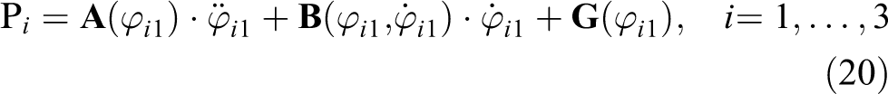
where
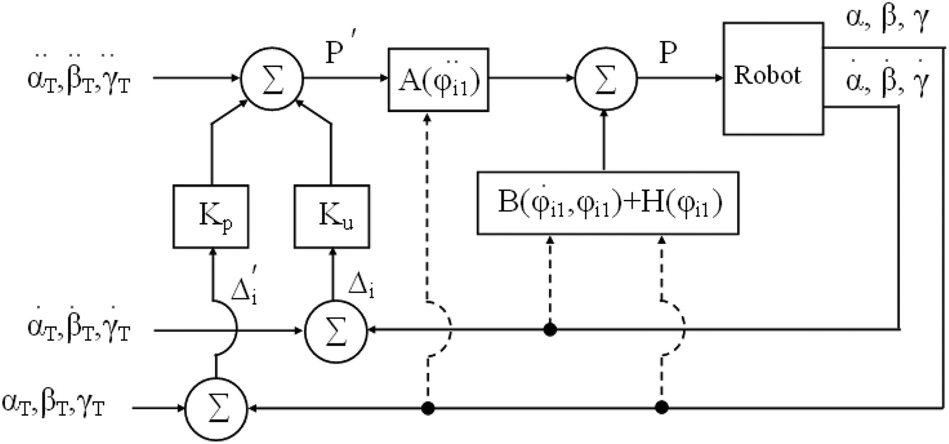
Block diagram of joint dynamic control.
The trajectory of the mobile platform described in equations:


where
To measure the magnitude of deviations, we use quadratic integral assessment

There must be

Rewrite equation (22) in a form appropriate to the oscillation link

where τ is the time
Set the damping ratio ζ = 0.707, time τ ≈ 0.011 time t = 0.011 (sec - second), and coefficients feedback γ 0 = 7200 and γ 1 = 120.
For perfect tracking, the signal is defined according to the following algorithm


Set the trajectory of the mobile platform

The simulation results are shown in Figure 5.
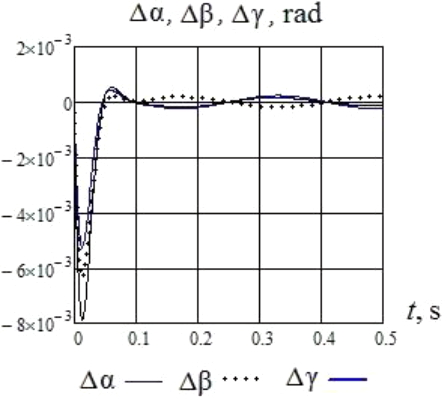
The simulation result of displacement.
The presented control method for the spherical parallel manipulators with three degrees of freedom is based on the concept of minimization of coordinates, velocity, and acceleration using inverse dynamic problems. This allows synthesis of this algorithm, which can realize a motion in accordance with prescribed trajectories.
Conclusion
The article presents a new spherical parallel mechanism with three degrees of freedom. It deals with the dynamical property of the new spherical manipulators parallel structure with three degrees of freedom. This article presents determination of acceleration input link and nonlinear oscillation output link.
The nonlinearity of the mechanical system is caused by the mutual influence drives. Influence between degrees of freedom and actuators leads to appearance in the dynamics of mechanisms. The nonlinear laws of change of coordinates of the output level are obtained. It is to be considered in the control. Oscillations are described by processing the type of beat, which converts energy from one coordinate to another.
The resulting solutions of the acceleration equations can be used further to solve the control problem. Results of the calculations of nonlinear oscillation input link of the manipulator are defined. The control algorithm of spherical parallel mechanism minimizes errors of the coordinate, speed, and acceleration. The control problem is analyzed via screw theory and the Jacobian matrix. The inverse dynamic model has been established and the computer simulation is performed by employing the virtual work principle.
Footnotes
Authors’ note
Kheylo Sergey is now affiliated with Department of theoretical mechanics, The Kosygin State University of Russia and Glazunov Victor is now affiliated with Mechanical engineering Research Institute named from A.A. Blagonravov of Russian academy of sciences.
Declaration of conflicting interests
The author(s) declared no potential conflicts of interest with respect to the research, authorship, and/or publication of this article.
Funding
The author(s) received no financial support for the research, authorship, and/or publication of this article.