
Abstract
In an actual grasp operation, grasp accidents (slant, rolling, turning over, and dropping) of in-hand objects occur frequently. Quantitative motion detection of in-hand objects is critical to optimize the grasp configuration and to improve the stability and dexterity of a grasp manipulation. In this article, an innovative method for quantitative measurement of the motions of in-hand objects is presented. Firstly, the slip information at object–finger interface between adjacent states is detected by three omnidirectional slip sensors; next, singular value decomposition method is applied to calculate the rotation and translation matrices according to the relative coordinate changes extracted from the slip information. Finally, Euler angles and the linear displacements which illustrate the motion of in-hand objects are quantitatively measured from the translation matrix and the rotation matrix, and the continuous motion track can be further established. Experiment results show that the proposed method is effective in detecting multiple motion information of in-hand objects.
Introduction
Stable and safe grasp in an unstructured environment is still one of the biggest challenges for grasp robotics. To get a successful grasp, most of the studies 1 –3 give their emphases on the grasp planning, namely, determining contact points of the finger on the object and formulating an appropriate gripper configuration. These researches attempt to acquire the optimal grasp planning based on the information of the object and the gripper obtained before grasp operation. But in fact, when exerting this optimal grasp planning in a real grasp operation, accidents, such as slip, slant, rolling, turning over, and even drop, frequently occur, because the grasp planning built in advance is based on ideal conditions and is inevitably affected by the actual working environment and factors. Therefore, most of the existing approaches are based on open-loop strategy, which is difficult to prevent the grasp accident and it is hard to analyze the reason for grasp failures. Conversely, if the in-hand object’s motions can be monitored and further be measured quantitatively, the gripper controller may guide the gripper to make corresponding response to prevent or alleviate the occurrence of accident. Furthermore, these quantitative sensing information can help the gripper to optimize the grasp planning for the grasp manipulations followed.
Besides, to impart the gripper more dexterity, many researchers 4 –7 recently explored a novel in-hand manipulation method named Extrinsic Dexterity, in which the environment is used to reorient the poses of in-hand objects. If the object is snatched up with a nonoptimal attitude, the gripper can actively use the environment to adjust its configuration to get a better grasp. To perform this extrinsic dexterity grasp scheme, the quantitative detection of the motions of in-hand objects is indispensable.
It can be concluded from the above research backgrounds that if the multiple motion information of an in-hand object, such as inclination, rolling, especially the precise linear displacement and rotation angles, can be detected, the stability and dexterity of a grasp manipulation is expected to greatly improve.
In this article, Motion Detection of in-hand objects refers to the measurement of the relative pose changes of the gripped object to the robot fingers, which are caused by the relative slip at the object–finger interface. The pose changes are quantitatively defined by linear slip along X/Y/Z directions and rotational slip around X/Y/Z axis.
Currently, the study on Motion Detection of in-hand objects is still insufficient. However, Pose Estimation of an in-hand object, a similar research area with Motion Detection, has been extensively studied. Pose estimation aims to determine the absolute location and the pose of the object so that the robot hand can accurately locate the object and correctly configure the grasp parameters. In earlier work, most systems 8 –11 rely solely on vision to locate an object and determine its pose. The performance of this strategy, however, tends to deteriorate during a manipulation task. This is due to the occlusions created by the robot hand and fingers, which conceal the object and hinder the accurate estimation of its pose. 12 Recently, many other sensing modalities, such as force, torque, and tactile sensing information, were added to the robot hand to complement the insufficient of vision-based methods. Bimbo et al. proposed several methods that combined visual information with other sensor modalities. While the iterative optimization algorithm 13 fused information from vision, tactile sensors, and joint encoders, the object pose was solely estimated from tactile and force sensing, requiring visual data for the initialization of the object pose. 14 Bimbo et al. 12 presented a principal component analysis (PCA)-based descriptor to find the position and orientation of a grasped object, by matching tactile data to an object’s geometric features. Similarly, Yitao et al. 15 proposed a particle filter that evaluates hypotheses of grasp poses by comparing tactile measurements and expected tactile information from computer aided design (CAD)-based haptic rendering models. Hebert et al. 16 and Martin et al. 17 proposed methods which fuse the stereo vision with force-torque and joint position measurements to determine the object pose.
Theoretically, the pose changes of in-hand objects can be easily computed through continuously estimating the absolute pose of a moving object. But in fact, there are at least two barriers for the existing pose estimation methods to be directly used for the motion measurement of the in-hand object. The first is that the physical information of the in-hand object, no matter the point clouds, 12,13 or the CAD models, 15 or three-dimensional (3-D) scale invariant feature transform (SIFT) features, 16 or contour features, 17 must be known in advance, and it is initially provided by the vision in these papers, which means these methods are not suitable for robot hand without a vision system. The second is that the time-consuming optimization algorithms, such as particle filter, 15 Bayesian static multiple model (SMM), 16,17 and covariance-based PCA methods, 12 are used for data matching in these methods, which are more applicable to the applications with low real-time request, for example, to locate the object in a grasp manipulation, whereas do not work well for the detection of continuous changes of poses.
Although slip sensors or tactile sensors are now wildly equipped in a robotic hand, most of them are solely used 18,19 to detect the occurrence of relative motion/slip at the object–finger interface. More recently, a few literatures have begun to study the motion patterns (linear or rotational slip) detection of in-hand objects. Su et al. 20 applied neural network on the tactile sensing data to discriminate the in-hand object’s linear slip from rotational slip, which can guide the robot hand to control the finger force accordingly. Similarly, Meier et al. 21,22 identified in-hand object’s translational, rotational slippage, and nonslip conditions from the tactile sensing data by using a convolutional neural networks. However, few literatures involve the quantitatively detection of the object’s motions, such as the linear displacements and rotational angles alone/around X/Y/Z axis, which can provide more sensing information for a stable and dexterous grasp manipulation.
In this article, we present a novel method to detect the multiple motion information of an in-hand object, specifically, (1) detecting the occurrence of slip, (2) measuring the object’s linear slip and rotational slip along/around X/Y/Z axis, and (3) computing pose changes and the continuous tracks of an in-hand object. The proposed motion detection scheme is based on the slip detection and Euclidean space transformation (singular value decomposition (SVD)) theory. Firstly, the slip information at the gripper–object interface is detected by omnidirectional slip sensors; then, the rotation and translation matrices which contain the motion changes between adjacent states can be computed using SVD theory; at last, Euler angles and the linear displacements along/around X/Y/Z axis of in-hand objects can be consequently obtained, and the continuous motion tracks of in-hand objects can also be rebuilt.
The major advantages of the proposed method are summarized as follows: (1) it can detect multiple motion information of in-hand objects; (2) it is less susceptible to the external factors, such as the unstable illumination and occlusions created by the work environment and the robot hand; (3) for gripper equipped with tactile sensors, tactile sensors can be used for the detection of slip information, no extra slip sensors are needed.
The remainder of the article is organized as follows. The second section is the principle and methods of proposed motion detection scheme, the third section explains the experiment setup and calibration procedures, the fourth section describes the experiment procedures and results for continuous track detection, the fifth section presents the verification experiments, the sixth section gives experiment results and analysis, and the seventh section is the discussion. In the end, conclusions are drawn in the last section.
Methods
Analysis model of motion changes
As shown in Figure 1, the cup is moving from state(n − 1) to state(n) and then to state(n + 1). If changes of displacement

Motion of the cup.
To facilitate analysis and calculation, as shown in Figure 2, m points on the surface are extracted to represent the cup, denoted by

where state(1)…state(n) represent different space states when cup moves and changes its attitude.

Cup’s moving model.
The relationship between adjacent states can be mathematically represented by

where

where
Matrix
As shown in Figure 3, when only the rotational component is considered, the rotation of the cup can be described by
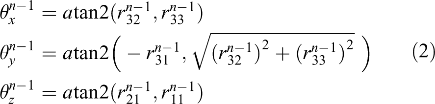
where atan2() is arctangent function. 23

Cup’s rotation model.
As represented in equation (1), the rotational matrix
Detection of object’s continuous track
Based on the analysis model in the section “Analysis model of motion changes,” if the rotation matrix

Cup’s continuous tracks.
Calculating of R and T
As analyzed in the section “Analysis model of motion changes,” the solution of rotation matrix (1) Define variables and the object function.
The rotation vector is denoted as a unit quaternion

where

A translation vector is defined by
The complete registration state vector is denoted by
Let
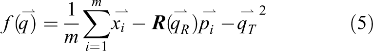
where m is the number of points to represent the object.
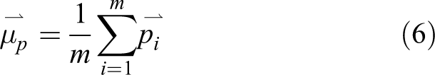
(2) Calculate the center of point set and form cross-covariance matrix.
The center of {

The cross-covariance matrix of

Compute the optimal rotation vector and translation vector.
The cyclic components of the anti-symmetric matrix
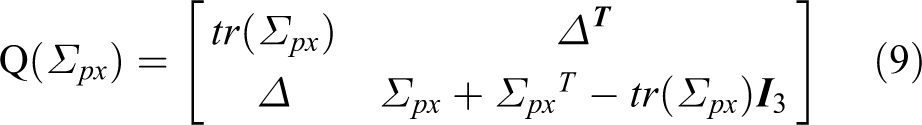
where
The optimal translation vector is given by

Thus, the translation matrix
Motion detection scheme
According to the section “Analysis model of motion changes,” to detect the motion of in-hand objects, the relative coordinate changes of the points on the object surface from state(n − 1) to state(n) should be measured. Theoretically, the more points selected to represent the object’s surface, the more accurate estimation of the motion changes we can achieve. However, in practical application, the contact areas between the object and the fingers are limited. It’s well known that at least three noncollinear points on the object surface are needed to represent the object. As shown in Figure 5, a triangle composed of three points, whose relative locations are restrained by the cup, is used to represent the whole cup.

Three noncollinear points on the cup.
Therefore, we design a detection scheme with three monitoring points (m = 3), as shown in Figure 6(a). At every detection point, a slip sensor is mounted in the fingertip. When a relative movement between the object and gripper fingers happens, the sensors can detect coordinate changes at the object–finger interface. Figure 6(b) shows the outputs of sensors 0, 1, and 2 at their respective position. The slip displacements L
0, L
1, L
2 and slip directions

Detection system design.
Experiment setup and calibration
Experiment setup
To verify the validity of the proposed method, we set up a gripper system with three slip sensors in the fingers according to the motion detection scheme presented in the section “Motion detection scheme.” As shown in Figure 7, the parallel gripper is manufactured by SCHUNK, whose model is WSG50. Its main parameters are (1) clamping range: 0–110 mm, (2) repeat positioning accuracy: ±0.013 mm, (3) clamping force range: 5–120 N, and (4) the parallel fingers are made of aluminum alloy.

Experiment setup.
In order to easily measure the actual linear displacement and rotation angle of the object, a cylindrical bottle is adopted as the in-hand object. The coordinate paper which covers on the object is designed to indicate the actual displacement and rotation angle, which is not necessary in the practical application.
According to the detection principle presented in the section “Motion detection scheme,” the slip sensor used in this scheme should possess the ability to detect the slip displacement and the slip direction. Nowadays, many slip/tactile sensors can meet this requirement, such as the widely used piezoresistive tactile sensor arrays 25,26 or the optical slip sensors. 27,28 In this article, a video-based slip sensor 29 is used to sense the multidimensional slip information. The slip sensor applies a micro-camera to capture the dynamic slip images at the surface of in-hand objects and the image processing algorithm is used to analyze the tracks of the slippage. The video-based slip sensor performs well on most of objects except those with transparent and reflective surface. 29
Figure 8 shows the accessory equipment for measuring the actual pose changes of the in-hand object, by which the object’s actual linear displacement along X/Y axis and angles

Experiment setup with measurement equipment.
Calibration of slip sensor
As shown in Figure 8, the test object is controlled to move alone X and Y axes with displacement


The calibration test is repeated five times and the mean of
Continuous track detection experiment
Continuous track detection procedures
The continuous track detection test is implemented as followed: Translate the object 60 mm along X axis; meanwhile, add an extra rotation component to the translation by slowly rotating the object 60° around X axis. Analyze the data from three sensors and calculate the rotation matrix The continuous motion track of the object can be acquired by using the method in the section “Detection of object’s continuous track.”
Continuous track detection results
The result of continuous motion detection is shown in Figure 9. In order to show the object under continuous changing states, a triangle composed of three noncollinear points on the object surface in YOZ plane (as shown in Figure 9) is selected to represent the whole object. It can be seen that the object is moving along X axis with a continuous rotation around X axis. The translation displacement along X direction is approximate 60 mm and calculated angle of the rotation around X axis is close to 60°, which are consistent with the actual conditions.

Continuous tracks of the in-hand object.
In the practical grasp manipulation, because of some limits of testing conditions, the actual tracks of the continuous motion state can’t be precisely measured; therefore, the continuous track detection test is designed and carried out qualitatively.
Verification experiments
To evaluate the effectiveness of the proposed method in quantitatively detecting the motion of in-hand objects, many verification experiments are carried out. Verification experiments focus on evaluating the measurement accuracy in linear displacements and rotational angles.
As mentioned in the section “Motion detection scheme,” the rotational angle around Y axis and the translational displacement along Z axis are pretty small because a parallel gripper is adopted in the experiment system. Therefore, only rotation angles around X/Z axis and linear displacements along X/Y axis are tested. The actual value of rotational angle and the linear displacement are measured by the universal instrument, such as an inclinometer and a Vernier caliper, respectively. The measurement accuracy is evaluated by comparing the test results acquired by the proposed method with the actual results measured by the universal instrument.
Rotation angle detection procedures
Rotate the object around X axis
As shown in Figure 8, the tested object with a diameter of 68 mm is clamped in the parallel gripper, while both ends are fixed on the holding frame. The tested object’s long axis is parallel to X axis and can rotate around X axis on the holding frame. The inclinometer is fixed on the test object, perpendicular to the object’s long axis. In the test, the object is rotated with a fixed angle. And the angle value can be recorded accurately by the inclinometer. It is considered as actual value and is denoted as
The detected value

Repeated nine times, the average of the absolute error will be

And the relative error is denoted by

The average of relative detection error is given by

Rotate the object around Z axis
As shown in Figure 8, similar to test (“Rotate the object around X axis”), the object will be rotated around Z axis by nine times and the actual value measured by the inclinometer
Linear displacement detection procedures
Translate the object along X axis
As shown in Figure 8, the object will be translated along X axis. The actual value of linear displacement
Translate the object along Y axis
The test setup is shown in Figure 8. The object will be translated along Y axis. Similarly to “Rotate the object around X axis,” the actual displacement
Experiment results and analysis
Results and analysis of rotation angle
Rotate around X axis
Tests were carried out following the procedures in the section “Rotation angle detection procedures.” The tested object was carefully controlled to rotate an angle of
Result of rotating around X axis.

The average of the absolute error

Rotation errors around X and Z axes. (a) Errors around X axis. (b) Errors around Z axis.
Rotate around Z axis
Following the process in the section “Rotate the object around Z axis,” the tested object was carefully controlled to rotate
Result of rotating around Z axis.
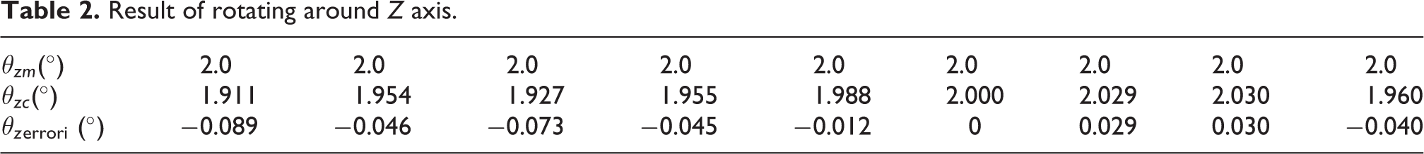
The average of the test absolute error
Results and analysis of linear displacement detection tests
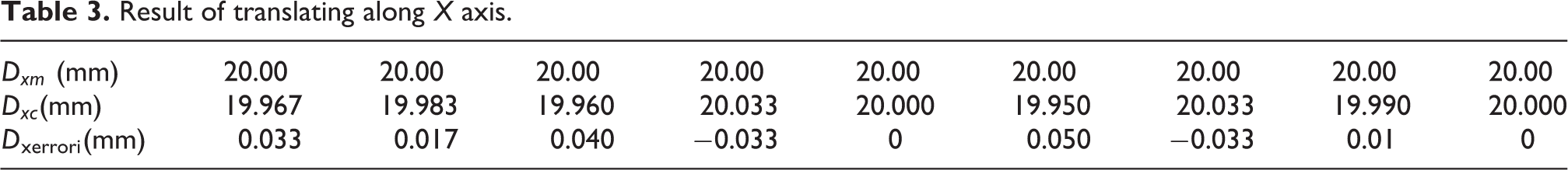
Translate along X axis
The test results are shown in Table 3, in which the first row is the actual value. The second row shows the detected value measured through the proposed method, and the third row is the absolute error. According to the section “Translate the object along X axis,” the relative errors are shown in Figure 11(a). The average of absolute error
Result of translating along X axis.

Translation errors along X and Y axes. (a) Errors along X axis. (b) Errors along Y axis.
Similarly, the error is mainly caused by the deformation of the object and the stretch of the coordinate paper which covers the in-hand object.
Translate along Z axis
The test results are shown in Table 4, in which the first row is the actual value. The second row shows the detected value measure through the proposed method, and the third row is the relative error.
Result of translating along Y axis.

According to the section “Translate the object along Y axis,” the relative errors are shown in Figure 11(b). The average of absolute error
Comparative experiments and analysis
As discussed in the section “Introduction,” there are few comparable literatures that study the quantitative motion detection/slip detection of multiple motion information of in-hand objects. Therefore, we compare our experimental results with what have been presented in literatures that study the pose estimation of in-hand object. In Bimbo et al.’s research, 12 the minimum errors of angle and linear displacement between the measured values and the ground truth values are 1.19°and 1 mm, respectively, in which the ground truth pose was displaced by a random rotation between 0° and 20° and a displacement between 0 mm and 10 mm around/on each directions [x, y, z]. The relative error of angle is consequently computed as 1.19°/20° = 5.95%, and the relative error of displacement is 1 mm/20 mm = 5%. In other literatures, only the mean absolute errors for pose estimation are reported, such as 5.2 mm in position and 1.51° in orientation 16 , 4 mm for position and 5° for angle 14 , and 5.2 mm and 3° for the average localization errors. 30 As shown in the section “Experiment results and analysis,” the relative errors for rotation and translation presented in this article are both below 4.5%, and the absolute errors for both rotation and translation are also far less than that reported in the comparative literatures.
Discussion
Experiment results verify that the proposed method is effective in quantitative motion detection of in-hand objects and also has the ability in rebuilding the motion tracks of an in-hand object.
From the experiment results and analysis, it can be found that the proposed method is only suitable for objects which are non-deformable or with low elastic deformation under the grasp force. For objects with high elasticity or that are prone to deformation at the gripper–object interface, there will be large detection errors.
In the experiment system, the video-based slip sensor is used to sense the slip information of the object. The proposed measurement scheme is equally applicable if the video-based slip sensors are replaced by other omnidirectional slip sensors. Tactile sensors equipped on a gripper can be used for the slip information detection, no extra slip sensors are needed. Because the data acquisition speed is commonly limited by the frame rate of the camera, the response speed in tracking the continuous changing motion of the object will prominently improve if the video-based slip sensors are replaced by other slip sensors with better dynamic property, for example, the piezoresistive slip sensor.
Although a parallel gripper is adopted in the experiment system due to the limitations of experimental conditions, the motion detection approaches proposed in this article can be easily transplanted to more complicated hands, such as Barrett hands, and other dexterous hands.
Conclusions
In this article, we present a novel method to quantitatively measure the motions of in-hand objects. In the proposed scheme, three omnidirectional slip sensors are used to detect the multidimensional slip information of an in-hand object. The SVD method is applied to compute the rotation matrix and the translation matrix on the sensed slip information between adjacent states. The linear displacements along X/Y/Z direction and rotation angles around X/Y/Z axis can be quantitatively measured from the translation matrix and the rotation matrix and the continuous motion track in 3-D space can be further established. Experiment results show that this method can accurately measure the motions of in-hand objects and rebuild the continuous changing tracks of the motion. The proposed method makes robots possible to prevent or alleviate the occurrence of the grasp accident and to optimize the grasp planning, which has a significant impact on improving the stability and flexibility of the grasp manipulation.
The future work is to explore the specific information hidden in the motions of in-hand objects to optimize the grasp planning and to help the grasp operation more stable and flexible.
Footnotes
Declaration of conflicting interests
The author(s) declared no potential conflicts of interest with respect to the research, authorship, and/or publication of this article.
Funding
The author(s) disclosed receipt of the following financial support for the research, authorship and/or publication of this article: This work is supported by the Fundamental Research Funds of Shandong University (Grant No. 2016JC001).