
Abstract
Parallel robots have a growing range of applications due to their appealing characteristics (high speed and acceleration, increased rigidity, etc.). However, several open problems make it difficult to model and control them. Low computational-cost algorithms are needed for high speed tasks where high accelerations are required. This article develops the nonlinear camera-space manipulation method and makes use of an extended Kalman filter (EKF) for the estimation of the camera-space manipulation parameters. This is presented as an alternative to the traditional method which can be time consuming while reaching convergence. The proposed camera-space manipulation parameter identification was performed in positioning tasks for a parallel manipulator and the experimental results are reported. Results show that it is possible to estimate the set of camera-space manipulation parameters by means of an extended Kalman filter. Using the proposed Kalman filter method we observed a significant reduction of the computational effort when estimating the camera-space manipulation parameters. However, there was no significant reduction of the robot’s positioning error. The proposed extended Kalman filter implementation requires only 2 ms to update the camera-space manipulation parameters compared to the 85 ms required by the traditional camera-space manipulation algorithm. Such time reduction is beneficial for the implementation of the method for a wide range of high speed and industrial applications. This article presents a novel use of an extended Kalman filter for the real-time estimation of the camera-space manipulation parameters and shows that it can be used to increase the positioning accuracy of a parallel robot.
Introduction
Industrial robot control has been an active area of research for several decades. Many efforts have been devoted to develop simple, yet robust and reliable algorithms to control complex robotic tasks. Furthermore, interest in the modeling and control of parallel robots has increased in recent years as a result of the versatility of these architectures. Some of their applications include pick and place operations, machine-tooling, and the performance of medical procedures.
Parallel manipulators consist of several closed kinematic chains that connect the end-effector to the base. This configuration makes them stiffer, relative to their total mass, than serial robots and yields an increased accuracy and velocity of the end-effector with a higher payload capacity. On the other hand, a disadvantage of parallel robots is their typically low cost-effectiveness due to their complex kinematics and rather expensive control units, as well as their poor workspace to robot-dimension ratio. 1
Moreover, their use is still sporadic due to several open problems inherent to the algorithms used to control them. 2 Indeed, the forward kinematic problem (FKP) of a parallel robots has multiple solutions and there is no standard technique to calculate them. 3 Even though particular FKP solutions may exist, their calculation is rather time consuming 4 and finding a complete solution becomes more complex with the number of degrees of freedom (DOF) of the end-effector. Also, numerical problems may be encountered even for robots with very simple architectures. 5 Furthermore, the singularities of a parallel robot exist in greater number than in a serial robot. For example, an anthropometric arm with 6 DOF has 16 singularities, while a Stewart’s platform with the same number of end-point DOFs has 43. 6
Another issue is the calibration of the kinematic model: the uncertainties in the manufacture and assembly of the robot makes it difficult to obtain an accurate Jacobian which is needed in most control approaches. 7 –9 Parallel robots require the calibration of a larger number of structural parameters when compared to serial robots. For instance, for a 3-DOF serial robot, having one link per DOF, nine parameters are needed to properly define its kinematic model (link length, link twist and link offset). One of the simplest parallel robots, 3-DOF delta robot, has 7 links and therefore requires the specification of 21 parameters. 10
There is a significant amount of work devoted to developing control approaches for parallel robots. 11 In particular, vision-based control techniques are a popular option for industrial robots’ pick-and-place tasks. Indeed, vision-based control is robust to different kinds of errors such as disturbances coming from the dynamic environment and uncertainties of the robot’s kinematic model. 12 It also directly provides information about the relative position of the end-effector with respect to its environment regardless of the uncertainties of the dynamic environment and of the robot’s kinematic model. On the other hand, new uncertainties associated to the vision sensors must be addressed. In particular, we need to account for extrinsic uncertainties coming from the sensor’s model when the model is used to reconstruct signals and intrinsic uncertainties coming from the sensor itself (i.e. illumination conditions, discretization noise, etc.). These new uncertainties are independent of payload and robot architecture and thus easier to deal with.
Several vision-based control methods can be found in the literature. For example, visual servoing, camera-space manipulation (CSM), stereo vision, and so on. 13 –27 These methods are used mainly to control serial manipulators and more recently, mobile robots.
The CSM can be considered as a calibration-free, vision-based control technique for robots and manipulators. To be successfully implemented, CSM requires neither an a priori knowledge of the robot’s Jacobian nor the calibration of the robot’s geometric or cameras’ parameters. The CSM is based on optimization techniques that minimize the end-effector positioning error within the field of view of the sensors used to control the maneuvers. It relies on the estimation of the relationship between the position of visual markers located on the robot and their corresponding position in images taken by at least two cameras. This relationship is defined implicitly in the so-called observation equations. 24 Compared to other vision-based control techniques, CSM is impervious to noise as sensitivity to it is eliminated by using historical data to average out the zero-mean uncertainty corrupting the image features. The CSM has been successfully applied to the control of a variety of 3-D positioning tasks with a wide range of applications including space exploration, warehouse maneuvering, industrial tasks, and mobile-robot control. 21,24,28 –33 Using the CSM, these tasks have been executed reliably, robustly, and with high precision with both serial and mobile robots. Meanwhile, validation of the CSM method for use with parallel manipulators is an open area of research.
There has been little research to apply vision-based control methods to parallel robots; most of the reported works rely on visual servoing techniques. A 2-DOF redundant planar parallel manipulator is controlled using visual servoing to perform drawing paths with positioning errors of 0.1–1.0 mm, an improvement from 1 to 3.6 mm when visual servoing is not used. 34 A similar control strategy was used to control a parallel delta type robot (Robotenis) with three translational DOFs. 16 The robot was able to interact with objects moving at speeds as high as 1 m/s, with a tracking error smaller than 20 mm. Further use of this technique has included force–position controls. For example, the Isoglide4-T3R1, an isotropic parallel structure with 4 DOF (3 in translation and 1 in rotation) was controlled in this way. 17 Simulation results achieved positioning errors of less than 1 mm. Finally, position–velocity controls have also been developed: the Adept Quattro, a delta type parallel robot, is controlled via a visual servoing approach where positions and velocities are estimated simultaneously using vision. 35 Precisions of 4 mm at a velocity of 0.025 m/s are reported.
More recently, the CSM has proven its value for the control of parallel robots. 36 This work utilized an academic prototype to provide a proof of concept and reported an average positioning error of 3.17 ± 1.14 mm. Still work has to be done in order to make the most of the intrinsic advantages of an industrial parallel robot. In particular, low computational-cost algorithms are needed to control parallel robots in high speed tasks where high accelerations are required.
When dealing with robot-manipulator control, a nonlinear estimation procedure for the estimation of the CSM parameters has traditionally been preferred. The traditional CSM parameter estimation is an iterative method which recalculates the vision parameters using a global optimization method requiring all previous measurements. This can become time consuming as the number of measurements increases. On the other hand, the extended Kalman filter (EKF) corrects the previous parameter estimate and without the global optimization may decrease computation time becoming a viable alternative for CSM-based vision control. Additionally, it can avoid potential numerical instabilities which could occur with iterative methods. 37 Such numerical instabilities linked to the pin-hole camera model have been previously reported, however, instabilities of the orthographic camera model, have not yet been proven. The orthographic camera model and not the pin-hole model is used in this work.
In this article, we compare two approaches for producing the so-called camera-space kinematics, associated to CSM control approach. Specifically, we looked at the performance of an EKF against the original nonlinear CSM formulation. The use of Kalman filters for vision-based robot control is well established 38 ; however, this work is the first to apply it to the CSM method in parallel robots. This article shows that using the EKF over the traditional CSM method decreases computation time while estimating vision parameters. Parameters obtained using the EKF maintain the same positional accuracy compared to the traditional method while better suited for real-time vision-based control of a parallel robot manipulator.
Methods
The pin-hole camera model approximated by means of an orthographic camera model
The mapping between a 3-D physical space and a camera bi-dimensional image-plane can be approximately derived from a perspective projection described using the “pin-hole camera model” (Figure 1). 39,40

Camera-fixed reference system.
This mapping is expressed as a function of the so-called view parameters, represented by vector

The camera dependent

where subindex i denotes an observation and Wi is the sample’s associated weighting factor.
Target estimation
The estimation of the 3-D coordinates of the target point (

where
Flattening
The applicability of the orthographic model can be increased after reducing its associated errors by means of flattening. The flattening procedure consists of modifying the raw camera samples in such a way that they become more consistent with an orthographic projection.
37,41
The modified samples

Considering the coordinate system attached to the camera as shown in Figure 1, the origin of this coordinate system is located at the focal point of the camera while the X and Y axes are parallel to the image plane’s horizontal and vertical axes, respectively. The Z axis is oriented along the optical axis of the camera. Therefore, Zi in equation (4) represents the Z-coordinate of the i-th detected sample, whereas Zr is the roughly anticipated value of the Z-distance of the target at the maneuver’s termination along each camera axis. In the experiments reported herein, Zr is continuously updated following the evolution of the estimated view parameters when new samples are obtained, as described in the section “Target estimation” and Appendix 1 “CSM model details.”
Extended Kalman filter
Consider the nonlinear system described by

for the k th measurement. The state vector

When estimating a set of constant states, the EKF may be written as follows 42

where
Approximation of view parameters by means of an EKF
There is evidence that an EKF can be used to obtain a good, even if not optimal in the least squares sense, approximation of the view parameters (

This expression can be used to define the state transition matrix as an identity matrix which operates on the value of the view parameters at any instant where the k th measurements is available 42

For every visual feature that is detected, its camera-space location will be represented using its flattened coordinate


In equation (10), the parameters

The EKF update equation will provide a new estimation of

where Wk is the relative weight given to k-th observation. The initial covariance matrix (

The equations involved in the formulation of the EKF based on visual marker observations have been previously presented. 43,44 Additionally, the CSM parameters can be derived using a previously described iterative method. 45 The work presented here offers a comparison between parameters obtained with an EKF and the traditional CSM algorithm. 46
Experimental platform
The following section describes the parallel robot utilized for the experiments.
An estimation of the view parameters and positioning tasks was implemented using a 3-DOF Delta-type parallel manipulator 10 and a two-camera vision system (see Figure 2). The parallel manipulator used is a Delta Parallix LKF-2040 composed of three kinematic chains that maintain the orientation of the mobile platform, thus offering three translational DOFs for the positioning of the end-effector. The radius of the fixed and mobile platform are of 150 mm and 50 mm, respectively. The robot’s actuators are located on the fixed platform and each one drives a 200-mm long input link connected to a 400-mm long parallelogram. More information on this device can be found in the literature. 47

Delta Parallix LKF-2040 robot.
A grid of
Forward kinematic model
Figure 3 shows a schematic view of a Delta-type parallel robot.
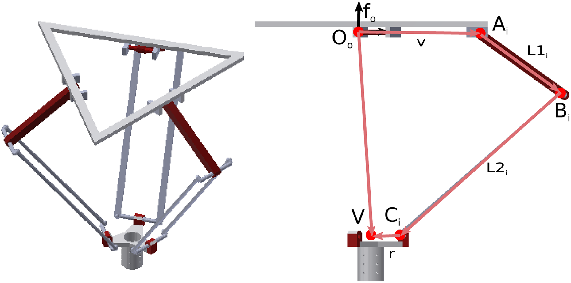
Schematic view of the Parallix LKF-2040 Delta-type robot.
From Figure 3

where

The forward kinematic model (FKM) for the Delta Parallel robot is known and has been previously reported by Maya et al. 47 and Coronado et al., 36 as well as the references therein. The FKM of this mechanism is based on a set of three closed chains which can be solved as the intersection of three spheres with radius L2 (15) with radius L2 and centered in (Xi , Yi . Zi ). Two points exist that solve this system of equations. From the two possible solutions, one is discarded for practical purposes as the end-effector is naturally attracted to the position closer to the ground due to the effect of gravity.
Positioning test
A series of positioning tests were carried out to evaluate the performance of the nonlinear view parameters (
Before conducting the experiment, a set of 410 end-effector positions and their corresponding camera-based coordinates were obtained. This data set is known as the preplanned data and is designed to include a large volume of workspace that is also within the cameras’ field of view. This set of points was used to generate a first estimate of the vision parameters. During the experiment, a laser beam was projected onto a target positioned in the workspace. The laser beam was used to create a non-permanent luminous marker, visible on both cameras, on the desired position for the tip of the end-effector. Using camera-space coordinates as input, the 3-D position of the target can be estimated using the camera parameters obtained previously. These values may not be exact but offer a first estimate of the
This positioning task was repeated three times for 10 randomly chosen target positions for a total of 30 data points. Additionally, as the end-effector approached the target, the view parameters were refined. Data used for refining the CSM parameters are obtained by calculating the end-effector 3-D position via joint angle measurements and the FKM, and its corresponding position measured on the cameras’ images. This can be performed in real time, along the approaching trajectory, as the necessary measurements and calculations are simple to perform. Ten intermediate sampling steps were used to refine the CSM parameters. Several strategies for assigning weights to a sample have been proposed. 46
Generally, the weight (Wk) of a sample increases as it nears the target. This yields locally valid CSM parameters that reduce the positioning error in the target point’s vicinity. 22
An empirical weighting scheme where the first intermediate point was assigned with weight of 10, the second one a weight of 20, the third one a weight of 30, and so on.
Results
The positioning errors obtained using parameters estimated based on EKF, and the traditional CSM method are shown in Figure 4 for the 30 experiments. This information is summarized in Table 1 as the average error and its standard deviation. There does not appear to be a bias error between both approaches. It should be noted that the parameters are locally valid due to the refinement performed by increasing the corresponding weight as the tool nears the target. In other words, errors are associated with the target directly and should not be a function of its position inside the volume. This is demonstrated in Figure 4, where the standard deviation of the errors is comparable with the error itself and is sub-millimeter. To further examine this, a t-test was performed using the data from the 30 positioning tasks and no significant difference was found between the accuracy of the robot when using vision parameters obtained using the traditional CSM identification and the proposed EKF

Measured error for positioning tasks using parameters estimated with the Kalman filter and traditional CSM methods. CSM: camera-space manipulation.
Positioning error and average computation time during the CSM parameter identification using the traditional algorithm and the EKF with data corrected via flattening.

CSM: camera-space manipulation; EKF: extended Kalman filter.
Discussion and conclusions
The results in Table 1, based on the number of positioning experiments mentioned in the previous section, show that using an EKF to estimate a camera’s view parameters can help to accurately and rapidly place a manipulator’s end-effector at a target position. This article aims to show the decrease in computation time when using the EKF for estimating CSM parameters with respect to the traditional method while maintaining a comparable performance. Note that the positioning error is directly linked to the quality of the CSM parameter estimation and not the estimation method. An in-depth study of the positioning error while using CSM is not presented here. However, interested readers are referred to the work of Rendon-Mancha et al., 22 who have studied the attained errors with and without the use of local samples, or that of Bonilla et al., 27 where the use of CSM for path-tracking was reported.
It should be noted that the EKF does not guarantee an optimal solution to the nonlinear problem 42 ; however, the results given here show that it is able to converge and find a set of suitable CSM view parameters. The EKF guarantees convergence which is something that the traditional CSM estimation approach does not. 37 Furthermore, due to is sequential nature, the EKF has a lower computational cost evidenced by its smaller computation time. The computational cost advantage of the EKF may aid in achieving higher end-effector speeds.
Figure 5 compares the performance of other vision-based control methods. The position of each circle indicates the reported average error with respect cycle time. The radius of each circle is proportional to the error’s standard deviation. Note that the differences in hardware utilized for each set-up are very difficult to consider and can greatly influence the cycle time. Also, there is great variability as to what is shown in Figure 5. The authors referenced in the figure do not define what is included in the cycle time, that is, it is not explicitly stated if the reported cycle time includes: image processing, robot movement, communication processes, and so on. The large error reported by Trashlosheros 16 may be due to reporting a tracking task, rather than a positioning one. The EKF implementation presented here appears to be an improvement with respect to the decision-making time.

Comparison of different implementations of vision-based control in serial and parallel manipulators, including the traditional CSM method and the proposed EKF. CSM: camera-space manipulation; EKF: extended Kalman filter.
The evolution of the work presented in this article is focused on the implementation of CSM as a vision-based algorithm for the control of parallel robots to account for moving targets. This could have industrial applications where the CSM model would account for robot calibration errors. Additionally, an in-depth study of the positioning accuracy as a function the robot’s position inside the workspace and the preplan collection strategy would be beneficial to understanding the limitations of the CSM method for industrial applications.
Footnotes
Acknowledgement
The authors would like to thank the C. Christopher Cooney and Brian Jackman endowed Professorship.
Declaration of conflicting interests
The author(s) declared no potential conflicts of interest with respect to the research, authorship, and/or publication of this article.
Funding
The author(s) disclosed receipt of the following financial support for the research, authorship, and/or publication of this article: Partial funding was provided by CONACyT under the Catedras 2016-972 project.