
Abstract
Composite workpieces, especially the complex-curved surfaces composite workpieces, have been increasingly used in different industries. Non-destructive testing of these parts has become an urgent problem to be addressed. To solve the problem, this article presents a dual-robot air-coupled ultrasonic non-destructive testing scheme and introduces the structure of the system and a general calibration method for the workpiece frame of a dual-robot system in detail. Importantly, this article proposes a tangential constraint method, which makes the probes completely aligned during the inspection process. Verification experiments and ultrasonic testing experiments for a glued multilayered composite workpiece were performed using the dual-robot air-coupled ultrasonic non-destructive testing system. A comparative experiment was also performed using a dual-robot water jet-coupling ultrasonic testing system. Experimental results show that the dual-robot non-destructive testing scheme and the tangential constraint method function well, and all the artificial defects on the sample can be detected by both kinds of testing methods. Vivid 3-D C-scan image based on the test result is provided for convenience of observation. In other words, a kind of flexible versatile testing platform with multiple degrees of freedom is established.
Keywords
Introduction
Non-destructive ultrasonic testing (NDT) is commonly used to test workpieces for defects and properties. However, traditional ultrasonic testing is severely limited by the physical coupling of ultrasonic transducers to the test medium such as liquid, gel, grease, glycerin, and so on. 1 The completely non-contact ultrasonic testing is among the most significant developments for characterization and analysis of most parts in the industries. Chimenti 2 described the developments in air-coupled transduction and electronics briefly and presented a comprehensive summary of air-coupled ultrasonic testing employed in the characterization or industrial materials NDT. Air-coupled ultrasonic testing is suitable for detecting materials with a density below the average. These material systems include wood, paper, and carbon or carbon fiber-reinforced composites. Although the lower mass density implies a relatively low acoustic impedance, most of the sound amplitude is reflected at the interface between air and the solid, which causes great ultrasonic attenuation. Two separate transducers (usually on opposite sides of a solid) are generally required to perform air-coupled ultrasonic testing.
For more than two decades, applications of this testing approach in industries sufficiently documented.
A pre-impregnated graphite–epoxy lamina had been detected by air-coupled ultrasonic transmission testing using a pair of 0.5 MHz ultrasonic probes by Chimenti and Fortunko, 3 and the testing results implied a high potential for reliable discrimination among material quality levels. X-Ray radiography and air-coupled ultrasonic testing technique were used by Hosten and collaborators 4 to detect impact damages in thin carbon fiber/epoxy composite plates and the results were very consistent. This further confirms the credibility of the air-coupled ultrasonic testing. Mahesh and Bhardwaj 5 provided kinds of high air/gas transduction ultrasonic transducers with varying dimensions and geometrical configurations based on novel acoustic impedance matching layers and high coupling piezoelectric materials. They also provided some application examples of air-coupled ultrasonic transmission testing method in the inspection process of wood and carbon fiber reinforced polymer/plastic (CFRP). Sanabria took multi-layered glulam beam as the test object, and the object was subjected to the air-coupled ultrasonic testing experiment. The spatial processing algorithm made the segmentation of the defect geometry significantly improved and the amplitude variability reduced by 10 dB. 6 Gómez Álvarez-Arenas studied properties in the thickness direction as well as in the paper plane of different paper grades (from 140 to 480 g/m2) using the air-coupled ultrasonic technique by wide band signals and spectral analysis. 7 Sergio J Sanabria, 8 Juerg Neuenschwander, 9 and Yiming Fang 10 highlighted the application of air-coupled ultrasonic testing in the detection of timber composite structures’ properties (i.e. density, moisture content, strength, and stiffness) as well as the wood defects (i.e. knots, cracks, decay, insect damage, and delamination).
It is well-known that the growing application of composite workpieces, especially the glued multi-layered composite workpieces (GMLCW), to improve stiffness-to-weight ratios and to develop lighter structures, and to improve corrosion, impact, and fatigue resistance. 11 The integrity of such parts is mainly affected by proper bonding of the individual composite layer. Ultrasonic NDT has proven to be the optimum NDT method to test the GMLCW. The main defects of this material are debonding, delamination, and inclusion. However, these workpieces often have complex-curved surfaces. The traditional Descartes coordinate ultrasonic testing systems with two degrees of freedom (2-DOF) or 3-DOFs, for example gantry or bridge-type systems can no longer meet the testing requirements of such workpieces.
In recent years, robotic NDT systems are attracting more and more attention. Both Louviot 12 and Maurer 13 established a prototype of a robotic NDT system that uses the off-the-shelf robot as transducers manipulators for automatic testing of complex-shaped parts. For an industrial robot, inverse kinematics that describe the mapping of the end effector from the Cartesian space to Joint space is crucial for efficiency in the design, motion planning, and the control of the manipulator. Zhou 14 presented an efficient algorithm based on extreme learning machine (ELM) and sequential mutation genetic algorithm (SGA) to determine the inverse kinematics solutions of a robotic manipulator with 6-DOFs. His algorithm minimized the computational time without compromising the accuracy of the end effector, and he also proposed a practical trajectory planning method for mobile robot. 15,16
Although robotic NDT method has many advantages compared with the traditional methods, in some cases, single-robot assisted NDT system cannot perform the testing task of some complex-curved surface parts. Many defects like debonding or delamination in composite workpieces (such as GMLCW) must be detected with ultrasonic through transmission testing method, because such materials have a large acoustic attenuation coefficient that does not support ultrasound signals passing from the inspection surface to the back-wall and back to the inspection surface. Lu presented a simple and effective method for synchronizing the workpiece frame of twin robot. The method can calculate the transformation matrix between two robots with only three non-collinear points in space, and he used the Lie algebra method to orthogonalize the rotation matrix. 17 Lu et al. 18 also demonstrated the kinematic constraint in twin-robot system for testing complex-curved surface parts. This is a very novel method, especially for the inspection of variable-thickness workpieces.
This article presents an air-coupled ultrasonic NDT solution for composite complex-shaped workpieces based on dual-robot system and proposes a control method for completely aligning the two probes on the opposite sides of the workpiece. Verification experiments were carried out based on the dual-robot air-coupled ultrasonic testing system we established. A complex-curved GMLCW sample with some artificial defects was tested by air-coupled ultrasonic through transmission testing method and water jet-coupling ultrasonic through transmission testing method. Experimental results show that the sizes and positions of the defects in the results of the two testing techniques are very consistent.
The remainder of this article organized as follows. The upcoming section introduces the basic principle of ultrasonic through transmission testing technology. The next section describes the introduction of dual-robot air-coupled ultrasonic NDT system including system components, system prototype, and calibration method of the relationship of workpiece frame relative to the robot base frame. Subsequent section describes a preliminary experiment that the trajectory was not calibrated by the tangential constraint method we proposed. Tangential constraint method and verification experiments of the method presented in detail in later two sections. A comparative experiment of water jet-coupling ultrasonic testing and a summary presented in the last two sections.
The basic principle of ultrasonic through transmission testing technology
In the past decades, through the joint efforts of people around the world, a sound theoretical knowledge of acoustics was formed. 19 According to the theory of acoustics, when ultrasonic waves are incident perpendicular to a part, there will be a reflected wave opposite to the direction of the incident wave on the surface of the part and generate a transmitted wave inside the part with the direction of the incident wave. The transmission coefficient T p of an interface is
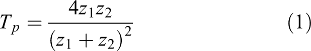
where z1 is the acoustic impedance of the first medium and z2 is the acoustic impedance of the second medium.
For air–solid interface, because of the great difference of acoustic impedance between the air and the sample (solid material), it is about five orders of magnitude, the acoustic energy loss between the two interfaces is huge and the transmission coefficient is very small. Therefore, to improve the amplitude and signal-to-noise ratio (SNR) of air-coupled ultrasonic signal, a power amplifier and a signal preamplifier must be integrated to the air-coupled ultrasonic system. Usually, the frequency of air-coupled ultrasonic testing is less than 1 MHz, and it is more suitable for transmission testing method compared with the air-coupled ultrasonic reflection testing method. The principle of transmission testing method identifies defects based on the degree of attenuation of the receiving signal. Principle of ultrasonic testing based on transmission method is shown in Figure 1.

Principle of ultrasonic testing based on transmission method. Tx and Rx represent the transmitting transducer and the receiving transducer, respectively. T and R represent the excitation signal and the receiving signal.
As shown in Figure 1, if there is no debonding defect between the two materials as shown in Figure 1(a), a slight interface reflection will occur at the interface, and the received energy of the receiving probe is the strongest relatively. If there is a small debonding defect on the interface as shown in Figure 1(b), a significant interface reflection occurs, and the transmitted ultrasonic energy is relatively weak. If there is a large debonding defect as shown in Figure 1(c), there will be no signal received by the receiving probe.
According to the inspection principle, the two probes need to be perfectly aligned during the inspection process. If the probes are cylindrical, the axial alignment of the two probes can meet the requirements of the inspection principle. However, if the probes are rectangular, it requires not only the axial alignment of the probes but also the alignment in the circumferential direction.
Introduction of the dual-robot air-coupled ultrasonic NDT system
System components
Despite those previous efforts, there remain some challenges to be tackled before automatic air-coupled ultrasonic NDT of any complex geometry composite parts becomes commonplace. Complex-curved surface parts in industries are increasingly used, especially in the field of aerospace. If the quality detection of such workpieces is not reliable and not comprehensive, it may result in some serious accidents. The low DOFs ultrasonic testing system cannot meet the requirements of modern industrial NDT. Therefore, it is necessary to develop a multi-DOFs flexible automated ultrasonic NDT system.
To make full use of the advantages of the air-coupled ultrasonic testing system, an automatic ultrasonic NDT scheme is proposed based on dual-robot synchronous motion technology. The system structure is shown in Figure 2.

Dual-robot ultrasonic NDT system. IPC is an industrial PC. NDT: non-destructive testing.
The whole system is composed of the hardware system and software system. The hardware system including two sets of 6-DOF robots, robot controllers, industrial computer (IPC), data acquisition board, ultrasonic pulser/receiver, ultrasonic probes. The software system including trajectory planning module, motion control module, data (position data and ultrasonic data) acquisition module, and defect visualization.
The synchronous motion control of the two robots is one of the core technologies of the whole system and plays an important role in testing process. The flexibility of the robots can realize the contour tracking of a complex-curved surface workpieces. It is possible to keep the probes’ axis normal to the testing surface in real time. To a certain extent, this reduces unnecessary energy attenuation when the ultrasonic transducers are not perpendicular to the workpiece surface. It is more conducive to ultrasonic testing.
System prototype
We have established a dual-robot air-coupled ultrasonic testing system. The two robots’ model are TX40 and they both come from the STAUBLI Group in Switzerland. The air-coupled ultrasonic testing system model is JPR-10CN-S3 comes from JAPAN PROBE Co., Ltd (Japan). The probes of the systematic standard configuration are rectangular ones and their size is 17 × 23 mm2, and their height is 33 mm. The frequencies are optional with 200 kHz, 400 kHz, and 800 kHz. The dual-robot air-coupled ultrasonic testing system is shown in Figure 3.

Prototype of the dual-robot air-coupled ultrasonic testing system. 1: Industrial computer; 2: master robot; 3: slave robot; 4: manual control pendants (MCP); 5: ultrasonic probes; 6: ultrasonic pulser/receiver; 7: external preamplifier; 8: robot controllers.
Calibration method of relationship of workpiece frame relative to the robot base frame
Before introducing these fundamental relations, the meaning of some symbols should be defined first. Frame
The specific approach is:
The robot arms are moved to bring the cone-shaped measuring tips to reach and record the three points we selected to determine the frame

where
The rotation matrix of frame

where
Similarly, the rotation matrix of frame

The transformation relation between workpiece frame and the robot base frames are determined by equations (3) and (4). An example of the setup used for measuring these points is shown in Figure 4.
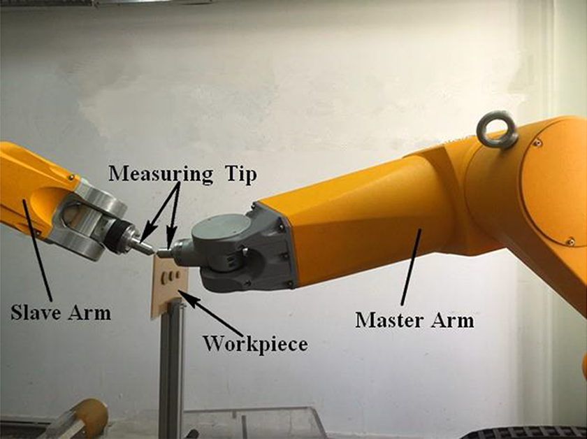
Example of workpiece frame calibration
Trajectory planning
The trajectory planning method adopted in this article is off-line programming. The trajectory planning software is developed based on CATIA. To control the robots, the trajectory relative to frame
Preliminary experiment
During the experiment, an arc-shaped GMLCW sample formed by bonding carbon fiber and rubber was selected as the testing object. Three rectangular artificial defects with sound-proof material were made and attached them to the sample to simulate the debondings. Their sizes are 17 × 17 mm2, 12 × 12 mm2, 8 × 8 mm2, respectively. The distances between them are 55 mm and 60 mm. As shown in Figure 5.
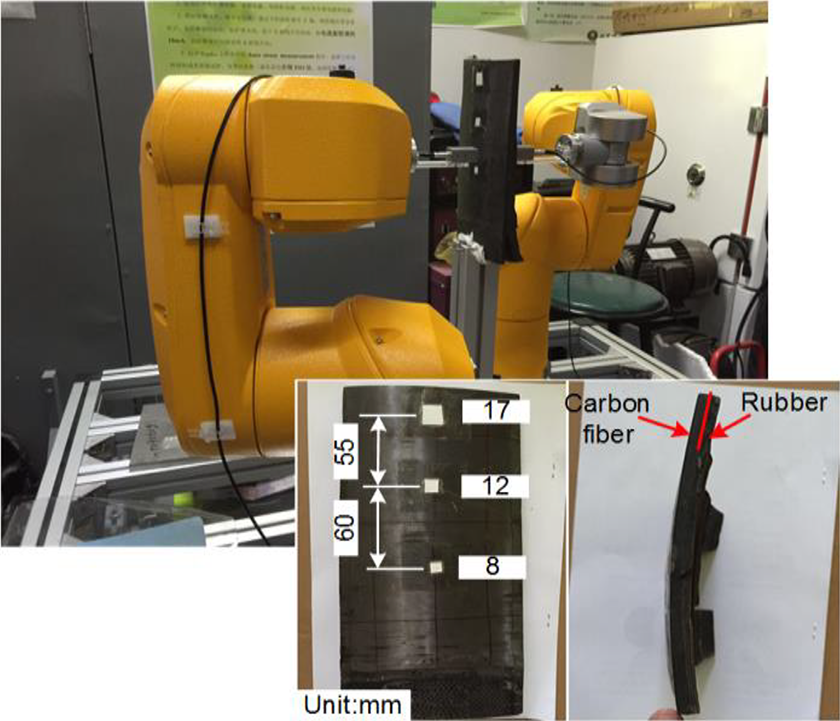
Dual robot air-coupled ultrasonic testing system and a testing sample
Experiment was carried out on the dual-robot system shown in Figure 5. A pair of air-coupled flat probes with 400 kHz were chose to carry out the C-scan testing. Receiving gain is set to 24 dB and excitation voltage is set to 400 V. Note that the air-coupled ultrasonic system has a preamplifier of 60 dB. A classical zigzag scan mode was performed with both step and increment interval of 1 mm. However, it turns out that problems are often not solved so quickly. Although this system works well for cylindrical probes, the rectangular air-coupled transducers on both sides of the workpiece were not perfectly aligned in the circumferential direction all the time during the testing process. As shown in Figure 6, several arbitrary locations of this process (line 1, line 2, line 20, line 39) were posted.

Snapshots of misaligned probes. These snapshots show some locations in the testing process when the probes were not calibrated (line 1, line 2, line 20, line 39).
This may inevitably affect the resolution and accuracy of the detection system since the piezoelectric wafer surfaces of the two rectangular transducers has an angle around the central axis of the two probes, the ultrasonic signal received by the receiving transducer will become smaller according to the principle of ultrasonic testing technology introduced in section “The basic principle of ultrasonic through transmission testing technology,” which may misjudge the normal portion as a defect. A better uncalibrated ultrasonic testing result of the preliminary experiment is shown in Figure 7. It is still difficult to identify artificial defects of 12 mm and 8 mm in Figure 7. Red represents detected defects.

Ultrasonic testing result when the probes were not calibrated
To illustrate the problem, the Cartesian coordinate data of the two tools ends (a transmitter and a receiver), and the corresponding robotic joints angles data were collected and analyzed. For a clearer illustration, a large step size (12.5 mm) between scan lines and approximately 2 mm increment size along scan lines were deliberately selected.
The measured Cartesian trajectory curves of the two tool center points (TCP) relative to frame
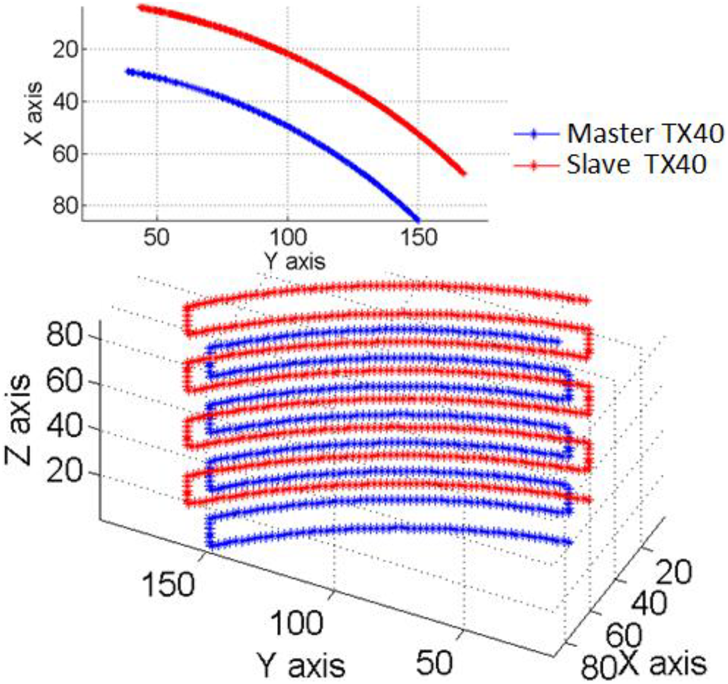
TCP trajectories of the two TX40 robots in the testing process when the probes were not calibrated. TCP: tool center point.
However, according to the above testing result, for rectangular air-coupled probes, the correct position and attitude only perpendicular to the part surface is not sufficient to obtain satisfactory testing results. To obtain the deflection angles of the two probes in the circumferential direction, the joints angles of the two robots were mapped to the workpiece frame

Deflection angles of the two probes in the testing process when the probes were not calibrated. X-axis represents the nth acquisition point and Yaxis represents the corresponding deflection angle.
Tangential constraint method
The above analysis prove that CATIA is a software that is expressly developed for machining and production operations of 5-axis machine tool rather than generating trajectories for a dual-robot NDT system. Post-processing is necessary before achieving a suitable trajectory for the dual-robot air-coupled ultrasonic NDT system.
Ultrasonic NDT require the sound beam perpendicular to the part surface at the test point. Louviot
12
also clearly emphasized that the axes of the ultrasonic beams of the transmitter and receiver sensors must be coaxial. For the dual-robot NDT system proposed in this article, it means that when the robotic end effectors move to a given test point as planned, the orientation of frame

Relationships between some specific frames.
According to the tangential constraint method, an auxiliary frame {

Auxiliary frame {
More specifically, take the first row as an example, the direction of X-axis is the direction of current point pointing to the next point. However, when the trajectory is not a straight line, the vector

Process of auxiliary frame establishment. The initial X-axis of auxiliary frame is referred as the
Before introducing the tangential constraint method, one thing needs to be explained is that the trajectory data generated by CATIA are arranged in a row array of the form [x, y, z, nx
, ny
,
The specific method is as follows:
If the coordinate of point

Z-axis of {

Y-axis of {

Correcting X-axis by the cross product of

These vectors can be used to get the rotation matrix

To precisely align the probes located on the opposite sides of the workpiece during the testing process, the X-axis directions of all auxiliary frames were constrained according to the above principle. The origin point of the tool frame was set in the central line of the rectangular transducers and the X-axis was set to be along the long side of the transducers. In this way, it is possible to ensure that the two transducers are completely aligned (axial alignment and circumferential alignment) when the robots scan the entire workpiece.
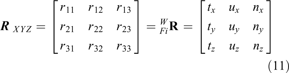
According to robotics, the rotation matrix

cos α and sin α are abbreviated as cα and sα for clarity. The unit of α, β, γ is degree (°). In fact, equations (9) and (10) are different expressions of the same matrix, which means
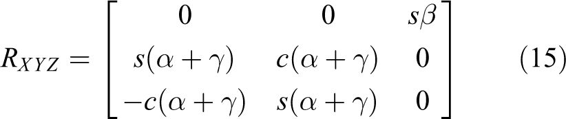
By equations (10) and (11), we can deduce

For calculations, the positive value is used, that is

The bivariate arctangent function Atan2(y, x) (sometimes called the four-quadrant inverse tangent function) is used to calculate α, β, and γ since it can automatically determine the quadrant of α, β, or γ.
If

If
In this situation, it is assumed that

The trajectory data need to be postprocessed with equations (5) to (16). This process constraint the X-axis and convert the normal vector direction cosines to the Euler rotation angles to fit the robot control requirement.
Verification experiments of the tangential constraint method
Verification experiment of trajectory and orientation
Under same conditions, experiment was carried out on the dual-robot air-coupled ultrasonic testing system shown in Figure 3. A classic zigzag scan mode was performed with both step and increment interval of 1 mm. The probes were completely aligned during all testing process. This will greatly improve the accuracy and credibility of the testing results. As shown in Figure 13, several arbitrary locations of this process (line 1, line 2, line 20, line 39) were posted.

Snapshots of aligned probes. These snapshots are of some locations in the testing process when the probes were calibrated (line 1, line 2, line 20, line 39).
To illustrate the calibrating result of the tangential constraint method clearly, the Cartesian coordinate data of the two tools ends and the corresponding robotic joints angles data were collected and analyzed. For a clearer illustration, a large step size (18 mm) between scan lines and approximately 2 mm increment size along scan lines were deliberately selected.
The measured Cartesian trajectory curves of the TCPs relative to frame

TCP trajectories of the two TX40 robots in the testing process when the probes were calibrated. TCP: tool center point.
Figure 15 is the curve of the deflection angles between the two probes in the testing process when the probes were calibrated. The maximum deflection angle is about 0.05°. Leaving aside the rounding errors in the calculation, it is nearly a perfect straight line. This means that the tangential constraint method is effective, practical and that it can ensure the X-axis of the tool frame (the long side of the rectangular air-coupled probe) always along the tangent of the trajectory, thus completely aligning the rectangular air-coupled probes during the testing process. An additional benefit is that the cables connecting the probes can be prevented from being wound around the robot arms.

Deflection angles of the two probes in the testing process when the probes were calibrated. X-axis represents the nth acquisition point and Y-axis represents the corresponding deflection angle.
Verification experiment of ultrasonic NDT
Experiment was performed on the same sample by the same system with the same scan parameters. The C-scan image of the calibrated testing result is shown in Figure 16. This is a satisfying result. It can be seen from the image that this system can identify 17 mm, 12 mm, and 8 mm artificial defects clearly. The distance between the defects is also consistent with the actual situation. Compared with Figure 7, it can be seen that the resolution of the system after calibration has been significantly improved.

Ultrasonic testing result when the probes were calibrated.
Comparative experiment of water jet-coupling ultrasonic testing
Although the air-coupled ultrasonic testing system has its own advantages, such as completely non-destructive and non-contact with the detected parts and does not require any coupling medium, a comparative experiment by water jet-coupling ultrasonic through transmission testing method was performed to improve the reliability of air-coupled ultrasonic testing. Experiment was carried out on the dual-robot system shown in Figure 17. Master and slave robots are RX160 and Tx90xL, and they both come from STAUBLI Group (Switzerland).

Dual-robot water jet-coupling ultrasonic testing system.
A couple of immersion probes with 1 MHz (Element size 0.5 inch, Damping 200 Ω, OLYMPUS (USA) unfocused transducer) were used to carry out the C-scan detection mission. One probe and one water jet nozzle were mounted on the end effector of each robot. A pulser/receiver (OLYMPUS 5077PR) was used to generate and receive ultrasonic signal. A data acquisition board (Logical Acquisition AL12200, with the highest sampling frequency of 200 MHz) was used for ultrasonic data collecting and transferring to industrial computer. Receiving gain was set to 10 dB and excitation voltage was set to 300 V. The sampling interval is 1 mm and step size is 1 mm too. The testing result is shown in Figure 18.

Ultrasonic testing result of water jet-coupling ultrasonic through transmission testing.
It can be seen from Figure 18, the water jet-coupling ultrasonic testing result is consistent with the air-coupled ultrasonic testing result. This experiment further validates the reliability of air-coupled ultrasonic testing results.
In total, 48,572 sets of position data and the corresponding ultrasonic data of the testing result were collected. The entire inspection process takes about 2.5 min. As shown in Figure 19, a 3-D C-scan image is generated based on this test data with the post-processing software Geomagic Studio. The 3-D C-scan image describes the size and the location of the defects more vividly and more clearly.

3-D C-scan image of the GMLCW sample. GMLCW: glued multi-layered composite workpiece.
According to the probes used during the experiments, it is obvious that the detection results using the immersion probes have a higher resolution, because these probes have a higher frequency. In practical engineering experiments, the appropriate testing method can be selected based on process requirements: water jet-coupling ultrasonic testing or air-coupled ultrasonic testing.
Conclusion
In this article, a multi-DOFs flexible ultrasonic testing method for GMLCW with complex-curved surfaces was presented. According to this method, a dual-robot air-coupled ultrasonic testing system was established. A general method of calibrating a workpiece frame relative to the robotic base frames of the dual-robot system was discussed.
Trajectory planning approach for the dual-robot air-coupled NDT system was studied and a tangential constraint method aligning the two probes was proposed through post-processing the trajectory data output from the CATIA software.
Trajectory verification experiments were carried out in which the two robots moved smoothly and the probes were completely aligned during all the testing processes when the two robots were controlled by the trajectory processed with this method.
The GMLCW sample was tested using the dual-robot air-coupled ultrasonic NDT system, and a comparative experiment was performed using a dual-robot water jet-coupling ultrasonic NDT system. The resolution of the system after calibration was significantly improved. Testing results of the calibrated system and the water jet-coupling testing system clearly present not only all the artificial defects on that sample but also the sizes and positions of the defects. The 3-D C-scan image made the testing result more vivid and clear.
These experimental results prove the effectiveness and feasibility of the proposed system and technique. This dual-robot testing method is especially suitable for automatic testing of large and complex-shaped components. This system is a flexible versatile platform with multiple DOFs. It is not only suitable for air-coupled NDT system and water jet-coupling ultrasonic NDT system but also can be developed into various NDT systems in future if equipped with other inspection equipment such as laser ultrasonic, electromagnetic, or eddy current devices.
Footnotes
Declaration of conflicting interests
The author(s) declared no potential conflicts of interest with respect to the research, authorship, and/or publication of this article.
Funding
The author(s) disclosed receipt of the following financial support for the research, authorship and/or publication of this article: This work is supported in part by the Graduate Technological Innovation Project of Beijing Institute of Technology (Grant No. 2018CX10018), the National Natural Science Foundation of China (Grant No.U1737203) and by the National Natural Science Foundation of China (Grant No. 51335001).
Supplemental material
Supplemental material for this article is available online.
References
Supplementary Material
Please find the following supplemental material available below.
For Open Access articles published under a Creative Commons License, all supplemental material carries the same license as the article it is associated with.
For non-Open Access articles published, all supplemental material carries a non-exclusive license, and permission requests for re-use of supplemental material or any part of supplemental material shall be sent directly to the copyright owner as specified in the copyright notice associated with the article.