
Abstract
Nowadays, industry tends to adopt the smart factory concept in their production. Technology intelligence is applied to use all the resources efficiently. Robots and vision system are masters in this kind of industry. However, information transfer between the robot controller and the vision system poses a great challenge. Data exchange between these two systems shall be secure, and the transfer must be with a very high level of accuracy. In this article, a multi-platform software application using a vision system is performed to control a Selective Compliance Articulated Robot Arm robot. The software solution includes the detection of defaults in a product by calculating a compliance rate using an efficient algorithm. An analysis of four different algorithms related to histogram-based similarity functions is set. Then, the most efficient algorithm is integrated into the application that provides a secure communication between three different operating systems. Experiments in a multi-agent manufacturing center validate the effectiveness of the proposed method. Tests demonstrate the efficiency of the data transfer between the vision system and the multi-platform software application and the Selective Compliance Articulated Robot Arm robot. This data transfer can be controlled in a high accuracy manner without any additional manual parameters tuning.
Keywords
Introduction
Monitoring and control are the key elements for any industrial and real-world applications. These complex, fault-tolerant, real-time computer systems typically include automation systems and supervisory control. Supervisory Control and Data Acquisition (SCADA) system consists of a supervisory control subsystem, which supports the operator’s control of remote equipment with security features and a data acquisition subsystem. 1 A typical SCADA system contains a human–machine interface (HMI) where information is collected and used by human operators; a computer that does the monitoring, remote terminal units (RTUs) that collect data from the sensors and transmit the data to the computers, programmable logic controllers (PLCs) that are used as a real-time controller; and finally a communication infrastructure connecting all the components listed above. 2 Industry tends to adapt new techniques and innovative production concepts. Rapidly, advancing hardware and software technologies have made it possible to develop a new generation of supervisory control and data acquisition systems. 2,3 Cyber-physical production systems (CPPS), relying on the latest developments of computer science, communication technologies and manufacturing science and technology, may lead to the fourth industrial revolution, frequently noted as Industry 4.0. 4 In the Industry 4.0, manufacturing systems are moved to an intelligent level. Thanks to the connectivity of the different agents (robots, workstations, automatons,…), it is possible to collect information, share, and provide it to create an automated decision and achieve flexible and reconfigurable manufacturing processes. 5 The steps of implementing Industry 4.0 criteria into an existing assembly system are represented in the study by Cohen et al. 6 The key technological elements of a smart factory are the Internet of things (IoT), cyber-physical systems (CPSs) technologies, and cloud computing. As a result, manufacturing systems are no longer limited to dealing with physical things, they are now able to manage a large range of data and knowledge. 7 –10 As an illustration, a novel method for the control of a reconfigurable manufacturing systems and its design method based on Petri nets is presented by Silva et al. 11 A comparison between management systems focused on PLC and management systems based on multi-agent systems is described by Peixoto et al.. 12 An intelligent simulation environment for manufacturing systems is proposed by Ruiz et al. 13 Design principles of a multi-agent system for a real-time resource management in an aircraft jet engine’s production are illustrated by Shpilevoy et al. 14 The key element of a smart factory is the industrial robot. 15 Industrial robots are incorporated in the automatic assembly to minimize the cost and the human errors while the area of the visual inspection has a great impact in the robotic guidance. 16
Robots are mostly in interaction with objects, and the accuracy of their location is very important. The review by Simoens et al. 17 examines how the merger of robotic and IoT technologies will advance the abilities of the current robotic system. Machine vision is used for extracting position coordinates. Robots can achieve better results when innovative vision methods are used. The communication between the vision system and the robot is rarely detailed because there is mainly a lack of technical specifications related to the data transfer model between the robot and the vision system. In this article, we propose a novel solution to control a Selective Compliance Articulated Robot Arm (SCARA) which is integrated in a flexible multi-agent manufacturing system. The approach consists in the design of a multi-platform software application that controls a SCARA robot. The solution is based on a robust software application. It includes the detection of defaults in an object by the estimation of a compliance rate and provides a secure data communication between three different operating systems (OS). This application provides a good precision and accuracy manner for the control of the SCARA robot. The proposed solution is distinguished from other software applications by including in the same application proficient image processing methods and providing a safe communication between three different OS.
The rest of this article is organized as follows. The second section presents an overview of related research. The third section illustrates the structure of the SACRA robot’s system. The fourth section presents the proposed approach’s methodology. The fifth section details the experiments and results. Finally, the sixth section concludes the article and presents issues for further work.
Related work
Several researches propose methods to control robots. In most of these studies, robots carry vision systems to gather information about the environment. Considering the state of the art, Santos et al. 18 propose an optimization method based on a genetic algorithm for the development of a navigation system for autonomous robotic sailing. Honarpardaz et al. 19 suggest a generic experimental method to verify existing finger design approaches. Koch et al. 20 describe the necessary steps to transform a mobile manipulator into a collaborative robot in flexible industrial environment. SCARA robots are often used as an educational example in several researches. In the study by Surapong and Mitsantisuk, 21 the control of the position of a SCARA robot based on a disturbance observer is proposed to move the robot in a desired direction. In the study by Pradhan et al., 22 an emulation, implementation, and evaluation of SCARA Robot in industrial environment are proposed. In the study by Gamaralalage et al., 23 the conversion of two or more manufacturing processes in a single machining setup based on a SCARA robot is presented. The architecture of the robot subsystem in a cyber-physical system manufacturing process and its implementation are provided by Luo and Kuo. 24 Hernández-Barragán et al. 25 put forward an approach to solve dual-arm cooperative manipulation tasks using the differential evolution algorithm. Šuligoj et al. 26 present a working multi-agent robot application using a stereo vision in a laboratory environment. Image processing and communication are handled using C++ multithread program and TCP/IP protocol. A method using a stereovision system attached to the robot is used for providing measurements of calibration points in space by Švaco et al. 27 An embedded cognitive and self-learning stereo-vision system that can be used to locate a robot’s position with respect to the workplace is proposed by Cristalli et al. 28 Schuster et al. 29 suggest an autonomous multi-robot for the manufacturing of aerospace structures. The system is set by combining computer vision, manual processes, and generic process execution in one system. The contribution of Voget et al. 30 consists of a projection and camera-based approach that provides capabilities for assisting workers in human–robot cooperative manufacturing processes. In the study by Guo et al., 31 an industrial robot is applied to complete the drilling work for a rocket shell. A vision system is applied to enhance the precision of mobile drilling. In Papanikolopoulos et al.’s study, 32 a robotic visual tracking system is proposed. It is addressed at unknown velocities in a 2-D space. In Ristic-durrant et al.’s study, 33 a mobile robot vision system is presented. The required robustness of the object recognition is accomplished by the introduction of the feedback control of colored objects’ segmentation. In Lian et al.’s study, 34 an embedded spatial coding approach is put forward to progressively encode the presentation quality of visual objects under receivers’ bandwidth limitation. The proposed approach is experimentally tested with a camera which is set up on a mobile robot. Cotera et al. 35 suggest an embedded system for the positioning of a wheeled robot on a production floor inside a factory by means of radio-frequency distance measurement and trilateration techniques.
SCARA robot’s system
The SCARA robotic manipulator
The SCARA robotic manipulator has six degrees of freedom (X, Y, Z, RX, RY, RZ). The structure of SCARA robot which is shown in Figure 1 consists of six joints. Joints 1, 2, 4, 5, and 6 are rotational joints, while joint 3 is a translational one. The movement of the robot is set as follows: Joint 1 has to move the robot to the x direction, joint 2 has to move the robot to the y direction, joint 3 has to provide a translation following the z direction, joint 4 has to move the SCARA robot to the RX direction, joint 5 has to move the robot to the RY direction, and joint 6 has to move the robot to the RZ direction.

Real SCARA Robot (a); SCARA robot’s joints (b); and SCARA robot’s coordinate systems (c). SCARA: Selective Compliance Articulated Robot Arm.
SCARA robot controller
The hardware robot controller is running with a specific OS (V+ OS). V+ system is a computer-based control system and a programming language specifically designed for Adept Technology industrial robots. The V+ system continuously generates robot-control commands and can concurrently interact with an operator. A communication based on Dynamic Data Exchange (DDE) is used to set a connection between a V+ OS and a Microsoft OS. The DDE protocol acts as a link between a client requesting device data and a field device that can provide the data.
36
This protocol is integrated into most software applications because its implementation does not need a complex programming. The two following elements provide the communication between the robot’s controller and the user’s interface (Figure 2): The V+ OS: It contains V+ algorithm that transcripts the received data via Ethernet port into V+ variables. Windows platform: It consists of a server application that acts as a link between the Ethernet protocol and the DDE protocol.
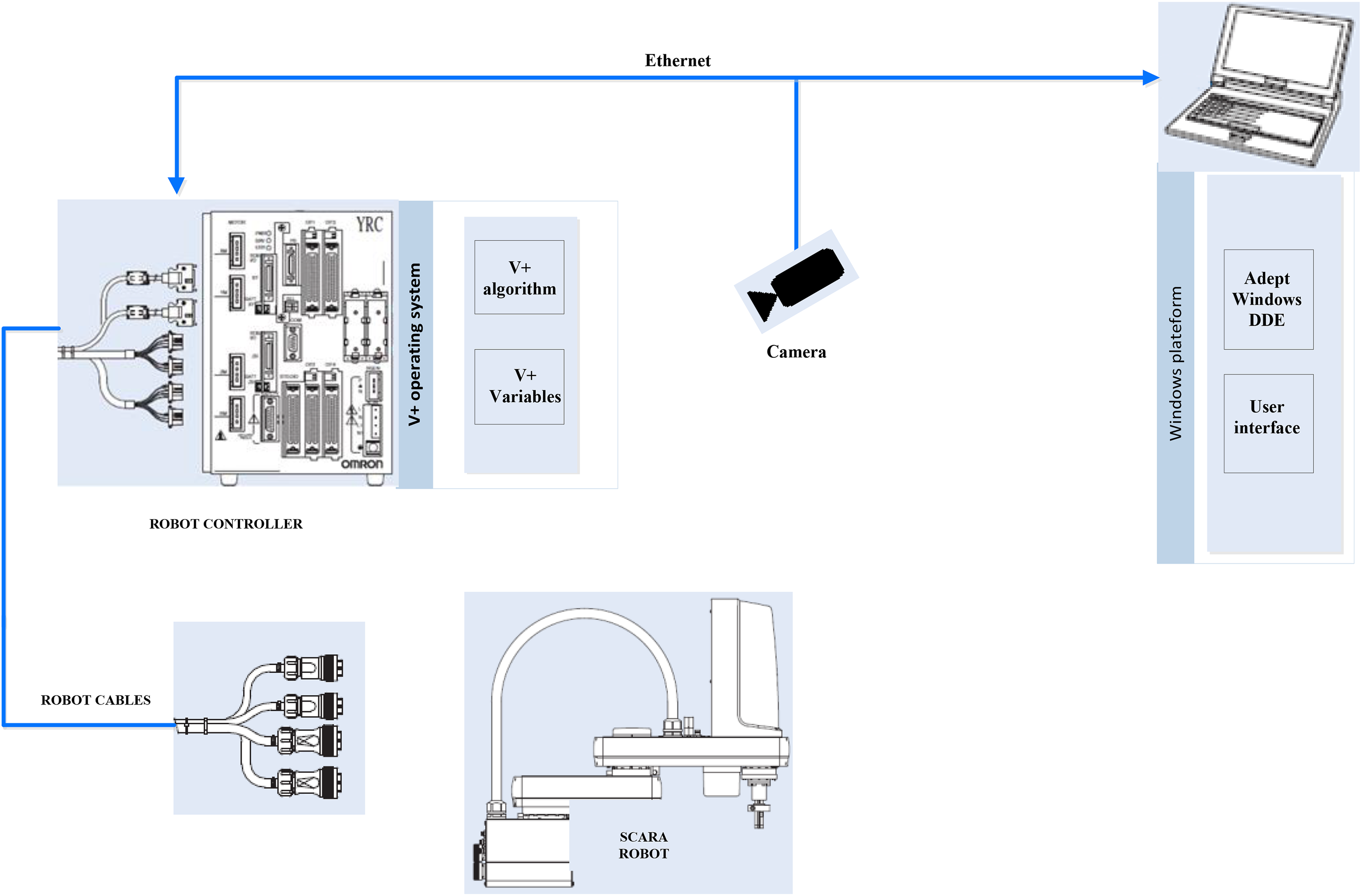
Adept controller’s architecture. DDE: dynamic data exchange.
Methodology
Here, we describe the design of the software application that controls the SCARA robot. First, we illustrate the mathematical model of the algorithm related to the vision system. An analysis of different histogram-based similarity functions is set. Then, the implementation details of the vision system are described. Finally, the proposed approach that provides the secure transfer between the vision system and the robot controller and its implementation details are illustrated.
Vision system
Similarity functions based on color features are the most intuitive feature of the image. It computes a conformity rate between two data sets. In addition, histograms are generally adopted to describe the conformity between two images. A histogram represents the distribution of values among the samples of the studied cases. In the previous studies, 37,38 authors compare several methods, wherein intersection, Euclidean, and correlation methods based on color histogram characteristics were respectively applied in the experiments of the same sample image. Zweng and Kampel 39 adopt a new algorithm using histogram similarity functions for pedestrians’ detection. Kurtz et al. 40 present a new distance called Hierarchical Semantic-Based Distance (HSBD) dedicated to the comparison of nominal histograms. The proposed distance can handle histograms that are generally compared, thanks to cross-bin distances. In an another study by Zweng and Kampel, 41 a new approach for people’s detection using a relational feature configuration is presented. In this work, the proposed methodology has two main steps: hue, saturation, value (HSV) conversion and then histogram analysis (Figure 3).
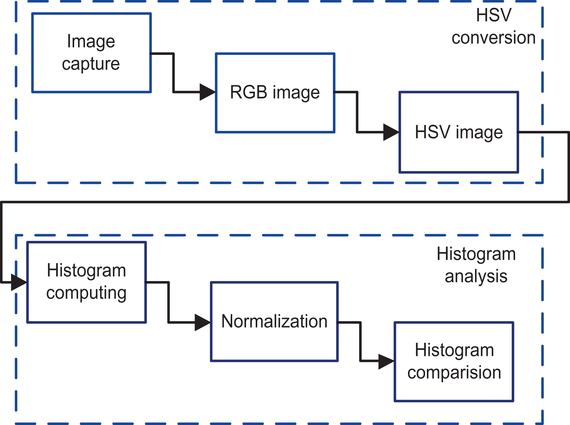
Vision system methodology. RGB: red-green-blue; HSV: hue, saturation, value.
HSV conversion
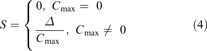
To describe colors, many color spaces have been used. The area of color’s usage can be described using the red-green-blue (RGB) color model or HSV color model. Chernov et al. 42 present the transformation equations for the conversion between the RGB and HSV models (1) to (5). The most crucial factor in an industrial environment is the effect of the brightness. The used method is based on the HSV space. It includes the criterion to separate color components from intensity. Figure 4 represents the HSV components of one snapshot of the used product. The proposed approach for the HSV conversion has three steps: image capture, RGB image, and then HSV image. A high definition (HD) camera is installed and used to take pictures of the objects. Then, the pictures are extracted and converted to RGB image and finally, the RGB images are converted to the HSV ones.


HSV components. HSV: hue, saturation, value.
Histogram analysis
A histogram represents the distribution of measurement values among the samples of studied cases. HSV color histograms of the object are calculated. H h-I1, H s-I1, and H v-I1 are respectively HSV histograms of the image I1 as presented in Figure 5. Each histogram contains n bins. Then, H h-I1, H s-I1, and H v-I1 are normalized by the total number of bins. Several histograms are calculated respectively for three images I1, I2, and I3. I1 is the base image, and I1, I2 are the test images. To compare two histograms, a metric must be used to express how both histograms will match. For this reason, similarity functions can be used to measure the distance between two images. The following similarity functions are used to compute the difference between two normalized histograms to obtain the best match.

HSV histograms. HSV: hue, saturation, value.
Correlation
In terms of histograms, the Pearson correlation coefficient is a measure of correlation between two histograms H 1 and H 2. It is the covariance of two variables divided by the product of their standard deviation. 43 The formula using histograms of an image I is given in equation (6)

N is the total number of histogram bins. Using this formula, d(H1, H2) can have the value between −1 and 1, where −1 and 1 represent, respectively, a maximal negative and positive mismatch, and 0 has no linear correlation.
χ 2 test
The χ 2 test is used to calculate the similarity between the expected and the observed frequency distribution based on Pearsons’s χ 2 test statistic. 44 The formula in terms of histograms is given in equation (7)

The lowest value is the best match. The value 0 indicates a perfect much.
Intersection
The intersection algorithm was suggested by Swain and Ballard. 45 The color histograms of multicolored objects represent robust information that leads to an efficient algorithm that recognizes 3-D objects from a variety of viewpoints. The highest value is the best match. The intersection is given in equation (8)

Bhattacharyya distance
The Bhattacharyya distance, which is a value between 0 and 1, provides bounds on the misclassification probability. The Bhattacharyya distance is a similarity measure between two probability distributions based on the Bhattacharyya coefficient. 46 The Bhattacharyya distance is given in equation (9)

Vision system design
Vision system implementation details
The comparison between the four methods described previously, namely correlation, χ
2, intersection, and Bhattacharyya, is an important step to find the best algorithm of the histogram similarity functions. The vision system is developed under Ubuntu 14.04 LTS OS. The choice of this OS is well studied depending on some software packages. The developed application uses the Open Computer Vision (Open CV). It consists of a programming functions library written in C++. A graphical user interface (GUI) is developed. The QT IDE and the QT creator binary are used. The implemented algorithm includes the conversion of samples from RGB model to HSV model followed by a computing of histograms. The application is successfully implemented using a HD camera. Figure 6 shows the user interface of the implemented application that allows the user to take a snapshot for the base image (a); take a snapshot for two test images (b); choose one comparison method or use all the four methods (c); display the numerical matching parameter for each method (d); and calculate the average of similarity when all the methods are used (e)

Vision system user interface.
Data transfer between the vision system and the robot controller
The major challenge in this work is to find a solution that connects three different OS platforms. The first platform is based on Windows OS and runs many asynchronous Windows applications. The second platform is the UNIX OS system that runs the vision system application, and the third one is related to the robot controller that uses the V+ OS. The three different platforms exchange several variables to control the trajectory of the robot according to the world coordinate system. Several studies are interested in the multi-OS systems, mostly the researches that are assigned to the embedded systems. 47,48 However, there are few researches related to the industrial environment due to the critical safety performance that this type of systems should provide. In this work, a software technique is used to provide a proper and safe environment for the multi-OS systems. This novel technique is based on the client/server concept (Figure 7).

Software system’s architecture. DDE: dynamic data exchange.
Implementation details of the software solution
The software application design
The present work is developed entirely with the C#. The choice of C# was mainly based on the language features related to the events and delegations. The developed software named multi-OS software application (MSA) allows the data transfer between three different OS. It connects the vision system which is under UNIX OS and the MSA that is implemented under Windows OS via a client/server concept. Furthermore, it permits the connection between the MSA and the V+ OS of the robot’s controller. Figure 8 represents a flowchart of the developed application. The vision system is considered as the client part of the application. It includes the image capture, HSV conversion, and the histogram analysis detailed previously. The percentage of similarity is sent to the server part after a connection was set between UNIX OS and the Windows OS. If the similarity check is passed successfully, the system sends a command to the robot controller to authorize the robot to continue its current task. In fact, when the connection and the similarity check are set, the client part receives the real-time position of the robot, and it sends the result to the server part. Meanwhile, the server part sets the connection between the Windows OS and V+ OS via DDE protocol connection. The connection is set using Adept software tools, such as Adept Window and AdeptWindows DDE. Adept Window is an application from Adept suite for personal computer (PC). It enables a PC to connect to the Adept controller using Ethernet and to display a real-time GUI. The user can communicate with the robot controller using specific commands. Figure 9 shows the AdeptWindows interface that displays the real-time state of the running processes. The AdeptWindows DDE provides a standard DDE server application that allows communication with other DDE applications running on the PC. In addition, the DDE functionality is embedded in the interface between the PC and the controller. Our application which is developed in C# aims to use the DDE protocol to communicate with the Adept controller through the DDE interface. The server receives the robot position from the V+ OS and the similarity rate from the UNIX OS. According to these two variables, the server decides whether the robot continues its present task or not and send the command to the robot controller using the DDE connection.

Software solution’s flowchart. DDE: dynamic data exchange; HSV: hue, saturation, value.

Adept Windows interface.
User interface of the developed application
MSA user interface
Figure 10 shows the user interface of the developed application (MSA) which is running under the Windows OS. This user interface acting as a client allows us to set the IP address of any software application under UNIX OS (a); connect/disconnect the vision system with the specified robot (b);check the connection between the V+ OS and the Windows OS (c); display the real-time position of the robot (d); control the position of the robot with a manual manner (e); receive the HSV from the vision system (f); and receive the similarity degree from the vision system (g)
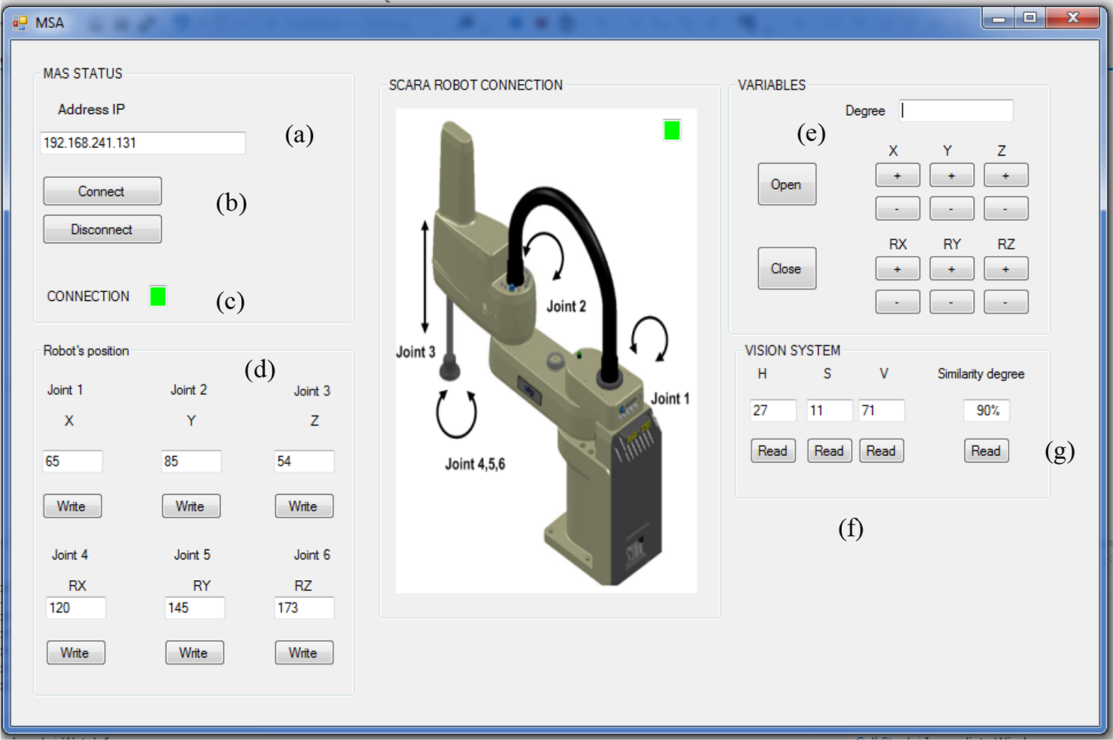
MSA user interface. MSA: multi-OS software application; OS: operating system.
Connection part user interface
Figure 11 shows the user’s interface of the developed application under UNIX OS. This user interface acting as a server allows us to connect the vision system with the MSA application (a); display the status of the current connection (b); receive the real-time position of the robot from MSA application and display it (c); and send the similarity degree to the MSA application and display it (d)

Connection part of user’s interface.
Experiments and results
The aim of experiments tasks is first to test the vision system’s performance and to choose the most efficient algorithm. Then, after integrating the algorithm in the software application related to the robot controller, several experimental tests must be done in the multi-agent manufacturing center using the SCARA robot. We performed sequences of tasks which are using a metal box as a product. The proceeding of the robot must be compliant with the data exchanged between the controller and the vision system. The concerned data include connection state, similarity rate, and the position of the robot.
Vision system quantitative results analysis
To come across the differences between the four comparison methods, an evaluation based on 100 images was made. A base image for the object was fixed and 100 test images were loaded. To have an in-depth evaluation on the used data set, the 100 test images are divided into four sections. The first section contains images with the highest similarity degree. The second section includes images where the position of objects is modified. The third section includes random images where the layout of the base image is modified with 40% degree. The final section covers images where the base image is reshaped with 90% degree. Table 1 presents some sample images for each section. Experimental results of the four algorithms are shown in Figure 12.
Sample images per section.


Comparison methods results.
Figure 12 illustrates the performance of the four methods with 100 sample images divided per section. It can be clearly seen that for the correlation and intersection methods, the higher the metric, the greater the match. However, for the Bhattacharya and χ
2 methods, the match is better when the ratio tends toward zero. Hence, to select the most efficient method for the histogram similarity functions, correlation is compared to intersection and Bhattacharya is compared to χ
2 considering the four sections mentioned in the previous paragraph. Section1: This section contains images with highest similarity degrees; correlation represents more linear variations than intersection method which shows several variations. In the same way, χ
2 involves more linear variations than Bhattacharya. Section 2: This section represents images where the position of objects is modified. In Figure 12, the intersection diagram shows fewer variations than correlation. However, for both Bhattacharya and χ
2, variations are almost the same. Section 3: This section includes random images where the layout of the base image is modified with 40% degree. All the diagrams of the four methods contain diverse variations. The modification is well detected for all the methods. Section 4: This section covers images where the base image is reshaped with 90% degree. Correlation highlights more the defect of the object than intersection. The same conclusion can be set for the diagram of χ
2 compared to Bhattacharya.
According to the previous analysis, it’s obvious that correlation and χ 2 are the most efficient methods for the detection of the object’s similarity. On the other hand, a unique method shall be used for the experimental tests. For section 1, correlation represents the most linear result compared to the other methods. For section 3 and section 4, both methods represent variations to highlight the malformation of the concerned object with 40% or 90% degree of modification. For χ 2, in sections 4, variations are relevant compared to section 2. Thus, this method focuses more on the object’s deformation than on its wrong position. However, for correlation, by comparing the results in sections 2 and 4, we found that the performances are approximately similar. Thus, for this method, a wrong position of the object can be easily detected as well as the detection of the deformation of the base object. Thus, the performance of correlation seems to be the most robust, and it outperforms the other approaches. In view of these analyses, the correlation method is used in the next experimental tests.
Tests and validation in the multi-agent manufacturing system
Manufacturing’s architecture
The interaction between the vision system and the robot must be tested. The approach is to identify defects of a product while it is moving from a workstation to another. In fact, several snapshots of a product are analyzed by the vision system. Then, according to the result of the vision system analysis, a command is sent to the robot’s controller. The manufacturing center on which we have tested our algorithm is composed of multiple connected entities (Figure 13). Some of the components of this industrial system are listed below: Four workstations: Each workstation includes a conveyor, stoppers, sensors, switchers, and radio frequency identification (RFID) for the pallet tracking. Four robots and their controllers.

Industrial environment overview (a); real view of the manufacture (b); RFID unit (c). RFID: radio frequency identification unit.
Tests and validation
Extensive loops of testing, debugging, and retesting were performed until the stability of the entire system was sufficient. The test consists in sequences of tasks done by the robot. In fact, the robot must detect a white object and put it in a metal box. Once the position of the two objects is correct, the robot must cover up the box. The Figure 14 illustrates the sequence of one of the performed tests. In step 8 shown in this figure, the vision system is involved by taking several snapshots of the current status of the two objects. At the present moment, the vision system starts to calculate the similarity rate using the correlation method described in the previous section. When the similarity rate is bigger than 70%, the robot covers up the box, otherwise the conveyor drives the pallet on which the box is put to the next workstation. The connection between the robot and the conveyer is set by the PLC. The aim of these tests is to check the effectiveness of the data transfer. When the robot covers up the box, this means that the information related to the similarity check and the robot manipulator’s position are safely exchanged between the three different OS (V+ OS, UNIX OS, and the Windows OS) using the designed applications. The entire process could be set manually using the buttons in the GUI (Figure 10) or automatically only by setting the connection between the robot’s controller and the developed applications. The manual and the automatic test phases were successfully completed, and the precision of the object recognition is quite good. Therefore, this problem may likely be solved by changing the calibration of the used camera.

Industrial robot’s sequences.
Conclusion
The application proposed in this article controls a robot’s actions using a multi-platform software application. An analysis to select the most efficient method of similarity check is set. The vision system can detect any type of defects in the product. The software solution includes the object shape check and provides a safe communication between three different OS. Following the result of the vision system, the software decides whether the robot continues its current task or takes the product to another workstation to correct the defect. The system has been tested with several aspects of the product, and the pick and place processes have been set with the required precision and reliability. In future work, the UNIX OS part of the proposed application will include an algorithm that contains the object tracking. In fact, the algorithm will choose the most reliable scenario in terms of execution time and precision to correct any defect in the object. Then, all the system will be implemented into a low-cost embedded system.
Footnotes
Declaration of conflicting interests
The author(s) declared no potential conflicts of interest with respect to the research, authorship, and/or publication of this article.
Funding
The author(s) disclosed receipt of following financial support for the research, authorship, and/or publication of this article: This article was supported by the Tunisian Ministry of High Education and Research: UR LSE ENIT.