
Abstract
To obtain better flexibility and multifunction in varying practical applications, several typical configurations of a modular reconfigurable cable-driven parallel robot are analyzed in this article. The spatial topology of the modular reconfigurable cable-driven parallel robot can be reconfigured by manually detaching or attaching the different number of modular branches as well as changing the connection points on the end-effector to satisfy diverse task requirements. The structure design of the modular reconfigurable cable-driven parallel robot is depicted in detail, including the design methodology, mechanical description, and control architecture. The inverse kinematics and dynamics of the modular reconfigurable cable-driven parallel robot considering diverse configurations are derived according to the vector closed rule and Lagrange method, respectively. The numerical simulation and related experiments of a typical configuration are achieved and analyzed. The results verify the effectiveness and feasibility of the inverse kinematics and dynamics models for the modular reconfigurable cable-driven parallel robot.
Keywords
Introduction
Cable-driven parallel robots (CPRs) are a robotic manipulator designed to control the position and orientation of its end-effector within the system’s workspace driven by flexible cables. 1 The CPRs are a particular class of parallel robots in which flexible cables are utilized to take the place of rigid links in the robot structure. Compared with rigid-link parallel robots, the CPRs have many potential advantages in terms of large workspace, high payload to weight ratio, low inertia, high speed and acceleration capability, simple and lightweight mechanical structure, ease of assembly and disassembly, and easy reconfigurability and scalability. 2 –4 Based on the abovementioned attractive characteristics, the CPRs have been extensively investigated by numerous researchers and widely applied in a great many of engineering fields in recent decades, such as large spherical radio telescope, 5 rehabilitation robot, 6 –8 3-D printer, 9,10 material and cargo hoisting, 11 wind tunnel test, 12 aerial camera, 13,14 high-speed assembly and pick-and-place operation, 15,16 haptic interface, 17 ultrahigh speed robot, 18 building construction, 19 rescue operations, 20 hazardous environment, 21 airplane maintenance, 22 and such specific purpose as back-heating or painting in ship building and aircraft construction. 3 Each of the aforementioned diverse applications has specific requirements, most of them are focused on a single operational task of the CPRs, which lead to different CPRs configurations. Therefore, the need for enlarging the role of traditional CPRs within the last few decades has caused the development of the ones that are modular and reconfigurable.
Modularity retains cost low by reusing common components, while reconfiguration extends the capabilities of what is realizable from a single-goal mechanism. The integration of these two design concepts has resulted in the development of modular reconfigurable robots (MRRs), especially in rigid serial robots, but modular reconfigurable parallel robots (MRPRs) have been developed recently. 23 The MRRs are made up of many basic modular components that can be rapidly assembled into different figurations to perform all kinds of tasks to satisfy different requirements. 24 The merits of the MRRs are given as follows: (1) shorten development cycle; (2) rapid design, manufacture, and low cost; and (3) adapt the changing operational needs and reduce maintenance. 25 In general, the MRRs can be classified into three categories according to the types of the module reconfiguration which include manual reconfiguring, self-reconfiguring, and self-assembly. Manual reconfiguring robots are in fact modular robots, which can only be reconfigured by manual assistance. Self-reconfiguring robots can perform reconfiguration by themselves after a robot system is assembled with some form of manual assistance. However, self-reconfiguring robots cannot achieve self-assembly. Self-assembly robots are the highest level of reconfigurability robot that can assemble and disassemble from their own modules automatically. 24
Some researchers have focused on the design and analysis of the modular reconfigurable cable-driven parallel robot (MRCPR), which can not only increase the number of features of the CPRs but also expand the workspace of the CPRs. As the same time, the MRCPR can also overcome the drawback of the CPRs related to the potential collisions, including cables and cables, cables and obstacles, and cables and surrounding environment. Li et al. 26 proposed a modular and reconfigurable cable-driven robotic grasper for grasping varying unknown objects in cluttered environments, which combines the features of full actuation and under actuation. Izard et al. 27 developed a reconfigurable cable robot to explore novel concepts for CPRs and illustrated its capabilities in industrial tasks. The specific view on the different components and the capabilities of reconfiguration were presented, as well as examples of layouts meant for various research and industrial projects. Gagliardini et al. 28 introduced a reconfigurable CPR to be employed in industrial operations on large structure. The reconfigurable CPRs can modify their geometric parameters to adapt their own features and be intended to sandblast and paint a large tubular structure. Gagliardini et al. 29 dealt with reconfigurable CPRs whose cable connection points on the base frame can be positioned at a possibly large but discrete set of possible locations. Anson et al. 30 investigated two planar mobile base configurations of the CPRs including the rectangular configuration and circular configuration, and their results were compared with as traditional fixed-base system. Compared with the MRPRs, very limited research has focused on the MRCPR. Thus, it is extremely necessary to analyze the proposed MRCPR. It is shown that the proposed MRCPR not only provides innovation in modular and reconfigurable CPRs design but also motivates further investigation of modular and reconfiguration CPRs.
The main motivation of this article is to investigate the structure design, typical configuration, inverse kinematics, and dynamics models of the MRCPR considering diverse configurations to satisfy the performance requirements in terms of modularity and reconfiguration, flexibility, and multifunction for the CDPRs in varying practical applications. Other motivation with respect to the MRCPR including the trajectory tracking, safety monitoring, and obstacle avoidance have been investigated in author’s former works. 31 The contributions of this article are as follows: (1) Several typical configurations of the MRCPR are analyzed, which can be obtained by manually detaching or attaching the different number of modular branches and changing the connection points on the end-effector to meet diverse task requirements. (2) The inverse kinematics of the MRCPR considering diverse configurations is formulated according to the vector closed rule. (3) The dynamics of the MRCPR considering diverse configurations is derived based on Lagrange method. (4) The effectiveness and feasibility of the inverse kinematics and dynamics models of the MRCPR are verified through the numerical simulation and experiments.
The rest of this article is organized as follows. The structure design of the MRCPR including the design methodology, mechanical description, and control architecture is described in the second section. Several typical configurations of the MRCPR are presented in the third section. According to the vector closed rule, the inverse kinematics of the MRCPR is derived in the fourth section. Based on the Lagrange method, the dynamics of the MRCPR is derived in the fifth section. The numerical simulation and related experiments of a typical configuration are conducted in the sixth section. Conclusions are summarized in the last section.
Structure design
Design methodology
The idea of designing the MRCPR is based on the use of modular branches as basic modular components. This design methodology applied in the article is based on the methodology proposed for the design for reconfigurability (DFR). The design of the MRCPR based on the DFR can be depicted according to the axiomatic design theory.
32
The design problem is to seek a set of design parameters

where
Thus, the objective of designing the MRCPR is defined that maximizes the number of the function requirements

where n denotes the number of modular branches and k denotes DOFs of the end-effector.
Mechanical description
The three-dimensional model and physical prototype of the MRCPR are shown in Figures 1 and 2, respectively. The main components of the MRCPR include a circular orbit, 6 sets of telescopic and rotatable modular branches, 6 cables, 6 tension sensors, 12 rope displacement sensors, an end-effector, a hydraulic station, a control cabinet, an industrial personal computer (IPC), and so on. Each modular branch mainly consists of a mobile platform, 2 servomotors, 2 motor seats, a hydraulic cylinder, 2 rope displacement sensors, a fixed pulley, a fixed pulley stent, 4 bevel gears, a cylindrical gear, 4 shafts, a gear shaft, a drum, 4 guide wheels, 17 bearings, 2 couplings, and so on. The assembly and disassembly diagram of the modular branch is shown in Figure 3.

Three-dimensional model of the MRCPR. MRCPR: modular reconfigurable cable-driven parallel robot.
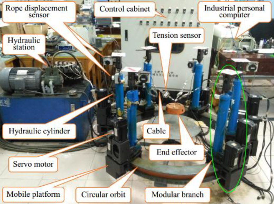
Physical prototype of the MRCPR. MRCPR: modular reconfigurable cable-driven parallel robot.

Assembly and disassembly diagram of modular branch.
Each modular branch can be rotated along the circular orbit by gear transmission, and the height of each modular branch can be changed by a hydraulic cylinder. The mobile platform and drum of each modular branch are driven by a servomotor, respectively. Four guide wheels of each modular branch are mounted inside the mobile platform, which can increase the stability and smoothness of the modular branch that is rotated along the circular orbit. For each cable, one end is attached to the corresponding connection point on the end-effector, while the other end passes through the fixed pulley on the top of the modular branch and twines on a drum fixed on the mobile platform. Notice that the huge disarray of cables will appear with respect to the fixed pulley stents during the movement of the end-effector approaching the borders of the workspace. So each fixed pulley on the top of the modular branch is installed on an omnidirectional fixed pulley stent to adapt to the changes of the end-effector positions. The layout guides the cable vertical to the drum axis for reliable coiling and uncoiling of the cable. A tension sensor is attached to each cable in series near the end-effector to test the cable tension. Two rope displacement sensors are installed on the top of each modular branch, which can accurately measure cable length and hydraulic cylinder height, respectively.
According to the diverse task requirements, the spatial topology of the MRCPR can be reconfigured by manually detaching or attaching the number of modular branches and changing the connection points on the end-effector. Compared with the traditional CPRs, the proposed MRCPR can be reconfigurable into a number of different configurations that are constructed by six identical modular branches. By detaching 1, 2, 3, and 4 modular branches separately, the MRCPR can be reconfigured from 6-DOF to 4, 3, or 2, respectively.
Control architecture
The system control architecture diagram of the MRCPR is shown in Figure 4. It can be decomposed into three layers, that is, the topmost host computer, intermediate programmable logic controller (PLC), and the bottommost controller including

Control architecture diagram of the MRCPR. MRCPR: modular reconfigurable cable-driven parallel robot.
It is can be connected through RS232 bus between the host computer and the intermediate PLC. The PLC consists of a Mitsubishi FX2N-48MR controller, power module, I/O and O/I modules, and so on. Its task is that gathers process parameters, performs real-time calculations, and carries out operation commands. The bottommost controller consists of
The PLC and motor drivers can command velocity, position, or torque set values for the motors. The current control loop and inner torque are embedded in all motor drivers. The data of each cable length and each hydraulic cylinder height are detected by a rope displacement sensor. The data of each cable tension are detected by a tension sensor. All of the above data are sampled by a data acquisition card and processed by the PLC.
Typical configuration
Several typical configurations of the MRCPR can be obtained by reconfiguring the different number of modular branches and changing the connection points on the end-effector, which are performed by manual assistance, as shown in Figure 5.

Several typical configurations of the MRCPR. (a) Configuration 1, (b) configuration 2, (c) configuration 3, (d) configuration 4, (e) configuration 5, and (d) configuration 6. MRCPR: modular reconfigurable cable-driven parallel robot.
Typically, CPRs with n-DOFs driven by m cables can be generally classified into three main categories: incompletely restrained CPRs (IRCPRs) when
Now that the proposed MRCPR in this article can alter its configurations by manual assistance, the pivotal is to find out a unified approach to deal with its diverse inverse kinematics and dynamics.
Inverse kinematics analysis
The schematic of the MRCPR is shown in Figure 6. Inverse kinematics solution is considered according to the position and orientation of the end-effector to solve

Schematic of the MRCPR. MRCPR: modular reconfigurable cable-driven parallel robot.
The end-effector is driven by
The angles of modular branches are expressed as

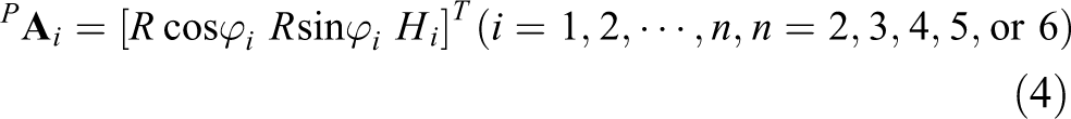
The coordinates of anchor points
The coordinates of connection points

where η denotes the starting angle of connection points
Thus the coordinates of connection points


where

where
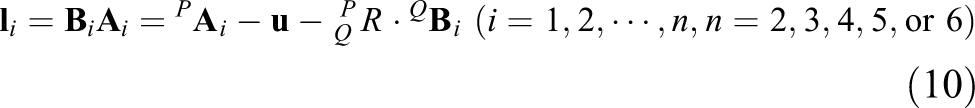
The length vector of the ith cable is expressed as
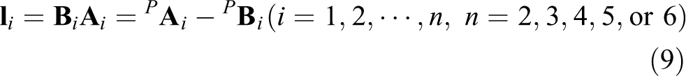
Substituting equations (4) and (6) into equation (9) yields
that is, the length of the ith cable is written as

Therefore, the velocity of end-effector of the MRCPR can be expressed as

The Jacobian matrix of the MRCPR is defined as the relationship between the velocity of end effector and the velocity of cables. Then the relationship between the velocity of cables

Jacobian matrix of the MRCPR can be obtained according to equation (10). Thus Jacobian matrix

Dynamics analysis
This section deals with the dynamics equation of the MRCPR, which definitely depicts the relationship between force and motion. It is extremely important for us to consider the dynamics equation in the process of the MRCPR design, control algorithm, and MATLAB simulation. Lagrange method is adopted to derive the dynamics equation of the MRCPR, which can be obtained by subtracting the total potential energy from the total kinetic energy of the system. To begin with, assuming that end-effector is a rigid object. The total kinetic energy K of the system is the sum of the translational kinetic energy K 1 and the rotational kinetic energy K 2 of the end-effector.
Inertial matrix of the end-effector with respect to the point Q can be written as

The diagonal elements of the inertial matrix,
Therefore, the inertial matrix can be rewritten as

The total kinetic energy of the end-effector is given in Cartesian coordinates as

Likewise, the only source potential energy of the end-effector is gravity, it can be expressed as

where m denotes the mass of the end-effector. g represents the acceleration due to gravity. Lagrange function of the system can be obtained as

The generalized coordinates of the MRCPR are defined as

Thus v,


Lagrange function of the MRCPR can be given as

Next, if Lagrange equation of the MRCPRs will be derived then two conditions hold:
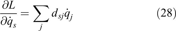
first, the total kinetic energy is a quadratic function of the vector

where the
Second, the total potential energy is independent of

The Euler–Lagrange equation of the system can be derived as follows. Since

in which


Therefore, the Euler–Lagrange equation can be expressed as

By utilizing the Lagrange equation and exchanging the order of summation, it can be shown that

Thus
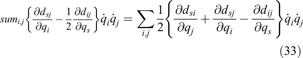
The terms
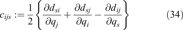
are known as Christoffel symbols. Finally, if
Then the Euler–Lagrange equation can be written as
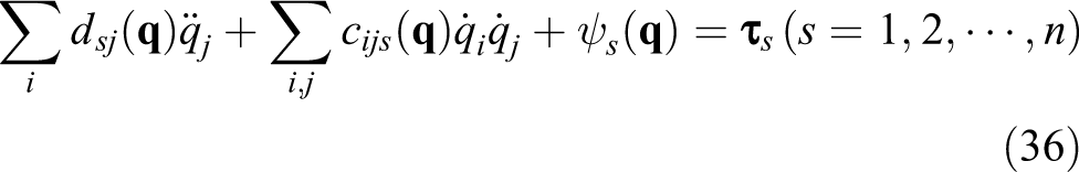
Equation (36) can be rewritten in matrix form as


Here, the k,j-th element of the matrix

where
Numerical simulation and experiments
Configuration 2 is selected from all typical configurations of the MRCPR, in which the performance of kinematics and dynamics can be verified by numerical simulation and a series of experiments. The angles and heights of three modular branches are locked during the course of the experiments. The change curves of cable lengths and cable tensions are obtained from the different angles and heights of three modular branches, which the results are compared and analyzed. The errors of cable lengths and cable tensions can be separately obtained by comparing simulation results and experiments results.
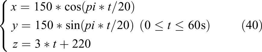
The trajectory equation of end-effector is a space cylinder spiral line, as shown in equation (40) and Figure 7.

Space cylinder spiral line.
Meanwhile, the specific geometric parameters of the MRCPR are listed in Table 1.
Geometric parameters of the MRCPR.
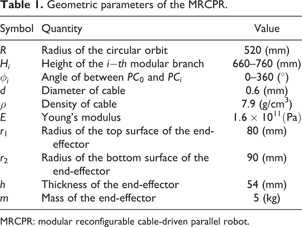
MRCPR: modular reconfigurable cable-driven parallel robot.
Cable lengths
The first group of cable lengths experiments is illustrated in Figure 8.
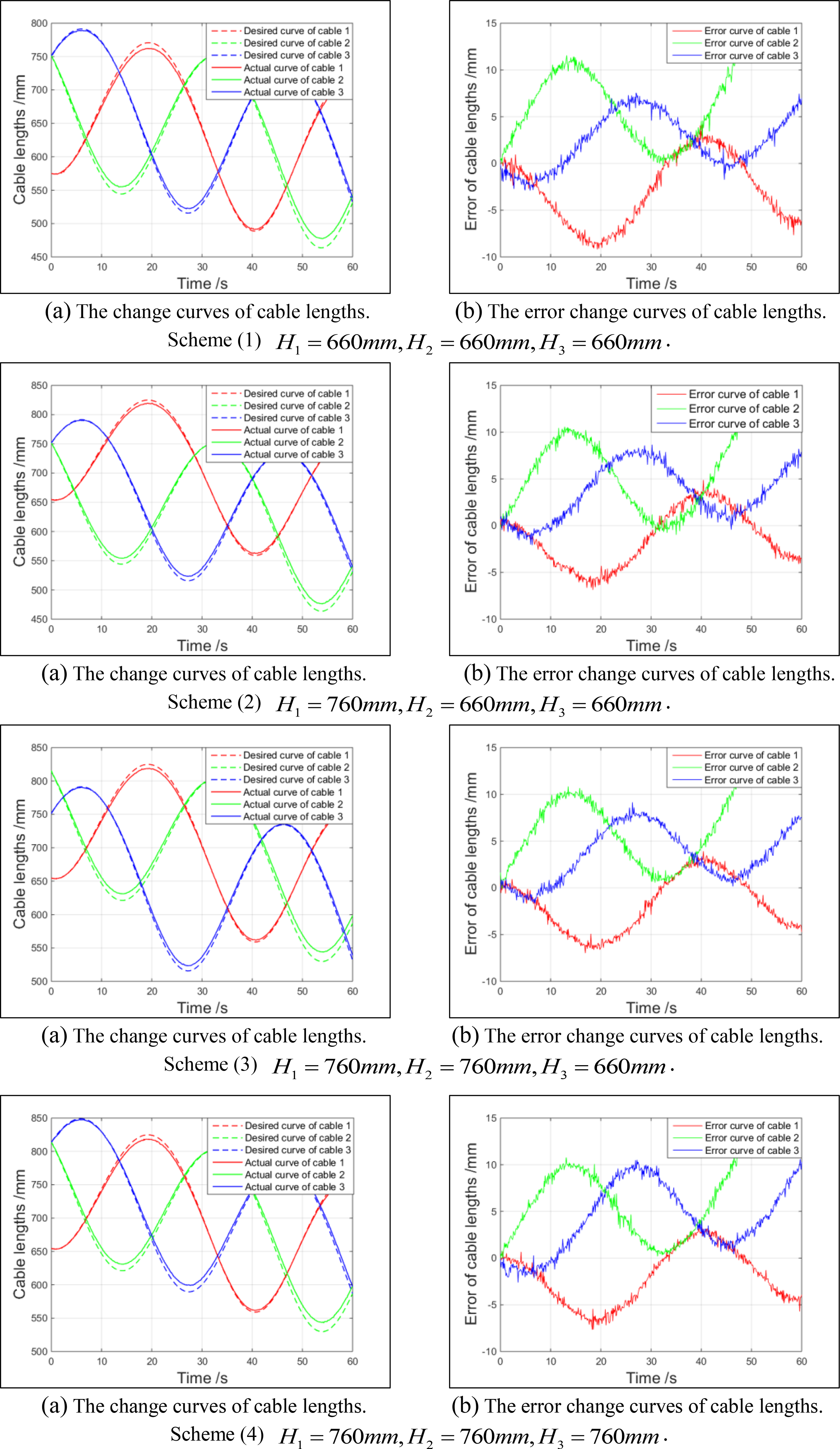
The change curves and error change curves of cable lengths (
The second group of cable lengths experiments is illustrated in Figure 9.

The change curves and error change curves of cable lengths (
The third group of cable lengths experiments is illustrated in Figure 10.

The change curves and error change curves of cable lengths (
Cable tensions
The first group of cable tensions experiments is illustrated in Figure 11.

The change curves and error change curves of cable tensions (
The second group of cable tensions experiments is illustrated in Figure 12.

The change curves and error change curves of cable tensions (
The third group of cable tensions experiments is illustrated in Figure 13.

The change curves and error change curves of cable tensions (
Three groups of experiments have been carried out to verify the kinematics and dynamics capability of configuration 2, which are shown in Figures 8 to 13. All experiments are based on the trajectory, which is a space cylinder spiral line. In Figures 8 to 13, cables 1, 2, and 3 are separately denoted by red, green, and blue lines, and the actual curve and desired curve of cable lengths and cable tensions are, respectively, represented by solid line and dotted line.
Three groups of experiments are compared and analyzed when the angles of three modular branches are (1)
In each group of experiment, the change curves of cable lengths and cable tensions are similar to sinusoid. As shown in Figures 8(a) to 10(a), three cable lengths gradually become shorter with the elevating of the end-effector from the initial point of the trajectory to the final point. It is obvious that cable lengths gradually become longer at the initial point of the trajectory when the heights of three modular branches are increased from 660 mm to 760 mm. With the height of each modular branch is changed from 660 mm to 760 mm, the cable length corresponding to the modular branch becomes longer. However, the second cable length becomes shorter when the angle
The error change curves of cable lengths and cable tensions separately display a similar shape which are shown in Figures 8(b) to 10(b) and Figures 11(b) to 13(b). The end-effector trajectory error is caused by diverse error sources, which include kinematic error, servo error, and deformation. Machining, assembly, and operation can lead to kinematic error, which is the primary error sources. 31 Notice that these deviations can be eliminated by the proposed robust iterative learning controller in author’s former works. 11 Therefore, the end-effector of the MRCPR can be elevated within the accepted error scope smoothly.
Conclusions
In this article, a MRCPR with several typical configurations has been analyzed. The proposed MRCPR can be reconfigurable into a number of different configurations that are constructed by six identical modular branches. The spatial topology of the MRCPR can be reconfigured by manually detaching or attaching the different number of modular branches and changing the connection points on the end-effector to meet diverse task requirements. By detaching 1, 2, 3, and 4 modular branches separately, the MRCPR can be reconfigured from 6-DOF to 4, 3, or 2, respectively. The modular branches can be not only rotated along the circular orbit but also raised or lowered by hydraulic cylinders. The structure design of the MRCPR including the design methodology, mechanical description, and control architecture is depicted in detail. The MRCPR with several typical configurations has the features of the IRCPRs, CRCPRs, and RRCPRs. The inverse kinematics and dynamics of the MRCPR considering varying configurations including 2, 3, 4, and 6-DOF are derived by the vector closed rule and Lagrange method, respectively. The numerical simulation and related experiments of the typical configuration are achieved and analyzed. The results not only verify the collaboration of modular branches each other but also confirm the effectiveness and feasibility of the inverse kinematics and dynamics models for the MRCPR.
Footnotes
Declaration of conflicting interests
The author(s) declared no potential conflicts of interest with respect to the research, authorship, and/or publication of this article.
Funding
The author(s) disclosed receipt of the following financial support for the research, authorship, and/or publication of this article: This work was supported by the National Natural Science Foundation of China (91748109 and 51575150).