
Abstract
In this article, a novel localization approach incorporating attitude and heading reference system and underwater altimeters is presented to accurately localize the underwater welding vehicles in spent fuel pools of the nuclear power stations. Different from the conventional underwater localization technologies, the presented localization approach is a more suitable approach in cases of confined structured water areas. Firstly, a multi-regions division localization algorithm is proposed for calculating the coordinate of the underwater welding vehicle through data from sensors. Also, considering the attitude errors of the underwater welding vehicle, the beam angle of the altimeters, and the boundary effects of cross-regions, an optimized multi-regions division localization algorithm is introduced for general applicability of the multi-regions division localization. Then, computer simulations are employed to evaluate the validity and the performance of multi-regions division localization and optimized multi-regions division localization. Finally, the efficiency of the proposed approach is confirmed via system experiments. The experimental results are consistent with simulation results which further indicate that the presented approach holds great potential in effective underwater vehicles localization for confined structured water scenarios.
Introduction
The underwater welding vehicles (UWVs) have been widely applied to automatic crack welding in spent fuel pools (SFPs) of the nuclear power stations. 1 –4 Self-localization of the UWV is essential for autonomous cruise and welding stability. Although much effort has been devoted to the underwater localization technology for UWVs, accurate localization in UWV operating is still challenging due to the intrinsic underwater conditions and technical restrictions in underwater welding work. 5
By now, numerous approaches have been proposed to realize the localization of underwater vehicles (UVs) in open-water areas (e.g. ocean and river). 6 –9 Among these approaches, dead reckoning localization has been widely adopted by utilizing the sensors independently of external information, such as inertial navigation systems (INS). Hegrenæs and Hallingstad 10 developed a model-aid INS for UVs. The output from an experimentally validated kinetic vehicle model was integrated in the navigation system to provide velocity aiding for the INS. However, INS suffers from error accumulation and zero drift during long-time run. Furthermore, high-precision INS is extremely expensive and bulky. Compared with INS, the acoustic localization systems including long baseline (LBL), 11,12 short baseline (SBL), 13,14 and ultra-SBL (USBL) 15,16 have been proved to be more cost-effective. UVs can communicate with one or more beacons fixed on the seabed or surface to measure the time of flight from beacons and get their current positions. Turetta et al. 17 addressed the accuracy of an LBL-based localization procedure and presented the results of an error budget analysis. Sato et al. 18 leveraged an SBL-based acoustic localization device instead of a conventional INS on autonomous UV (AUV) Tri-TON 2 in order to estimate its position and orientation in real time. Nevertheless, in LBL, it is a difficult, time-consuming and expensive process to deploy the transponders. Moreover, in SBL and USBL, there is a need for a ship in the operation region which is not suitable for many applications. 19,20 In parallel, global navigation satellite system (GNSS) using the GPS, GLONASS, Galileo or Beidou system has been widely applied on land. 21,22 Since the GNSS cannot work underwater due to bad attenuation of radio frequency signals, it is usually fused with other localization approaches. Thomas 23 developed a GPS intelligent buoy system by adopting four surface buoys equipped with GPS receivers and submerged hydrophones to broadcast satellite information underwater. Lee et al. 24 proposed sensor fusion of GPS and INS using Kalman filter (KF) in which the GPS/INS data were utilized for estimating the position of AUV and KF elaborate the position estimation. With the development of simultaneous localization and mapping (SLAM), acoustic and optimal imaging localization systems have also been widely used such as imaging sonar or camera. Ferreira et al. 25 built a real-time mosaic of the seafloor relying on an SLAM framework using a camera and a laser triangulation altimeter. They provided the Romeo ROV with a relatively rough visual map of the seafloor to support basic navigation and proved the effectiveness of the approach through experiments. Jung et al. 26 proposed a vision-based SLAM of AUVs, where underwater artificial landmarks are used to help visual sensing of forward- and downward-looking cameras. The proposed method is validated by an experiment performed in an engineering basin.
Different from open-water scenarios, the SFP is an indoor pool, typically 30 m in depth with bottom 5 m equipped with storage racks to hold fuel assemblies from the reactor. Particularly, in a real SFP, the localization of UWVs should be operated in confined water areas. In this scenario, the UWV needs to realize free motions in the complete area of the SFP. Furthermore, the UWV should be able to get close to the bottom and sidewalls of the SFP for stable crack welding. The abovementioned requirements bring challenges for the development of high precise localization technology in the confined structured water areas. To the best of our knowledge, all the localization approaches mentioned above are not amenable to localize UWVs in SFPs accurately due to the particularities of SFPs.
In this work, we present a novel approach to localize the UWV in the SFP by incorporating the attitude and heading reference system (AHRS) and two underwater altimeters. The AHRS provides 3-D orientation by fusing the data from gyroscope, accelerometer, and magnetometer. In parallel, two underwater altimeters are installed in front and on the right side of the UWV, respectively, to measure the distances between the UWV and the sidewalls. Moreover, a multi-regions division localization (MRDL) algorithm is proposed which combines the data of both AHRS and altimeters. An optimization of the MRDL is presented for general applications in practice. Finally, simulations and experiments are set up to validate the accuracy and the robustness of these two algorithms. Although this localization approach is proposed for UWVs’ localization in SFPs, it is also capable of effective in any other confined structured water areas and, therefore, this work will be useful for future studies on underwater localization in confined water areas.
MRDL algorithm
In this section, a novel localization approach for UWVs in SFPs cooperating with the AHRS and altimeters is proposed and described in detail. As presented in Figure 1, the AHRS provides the UWV’s attitude information including roll angle, pitch angle, and yaw angle. Two underwater altimeters are installed in front and on the right side of the UWV, which are used to measure the distance between the UWV and the sidewalls of the SFP.

The installation positions of the two underwater altimeters. One is installed in front of the UWV with the other on the right side of the UWV. UWV: underwater welding vehicle.
The attitude of the UWV is described as
The shape of the SFP is a standard rectangle. Let

The earth-fixed reference frame
Let

where
The heading angle of the UWV satisfies the condition

The new reference frame
Let

where
The z coordinate of the UWV can be measured by the pressure transmitter directly. Therefore, the MRDL algorithm only concerns about the x and y coordinates, that is, the position vector of the UWV
In

Four regions of the plane
The dimensions of the SFP in

1) The UWV locates in region 1 as shown in Figure 5 at time

where
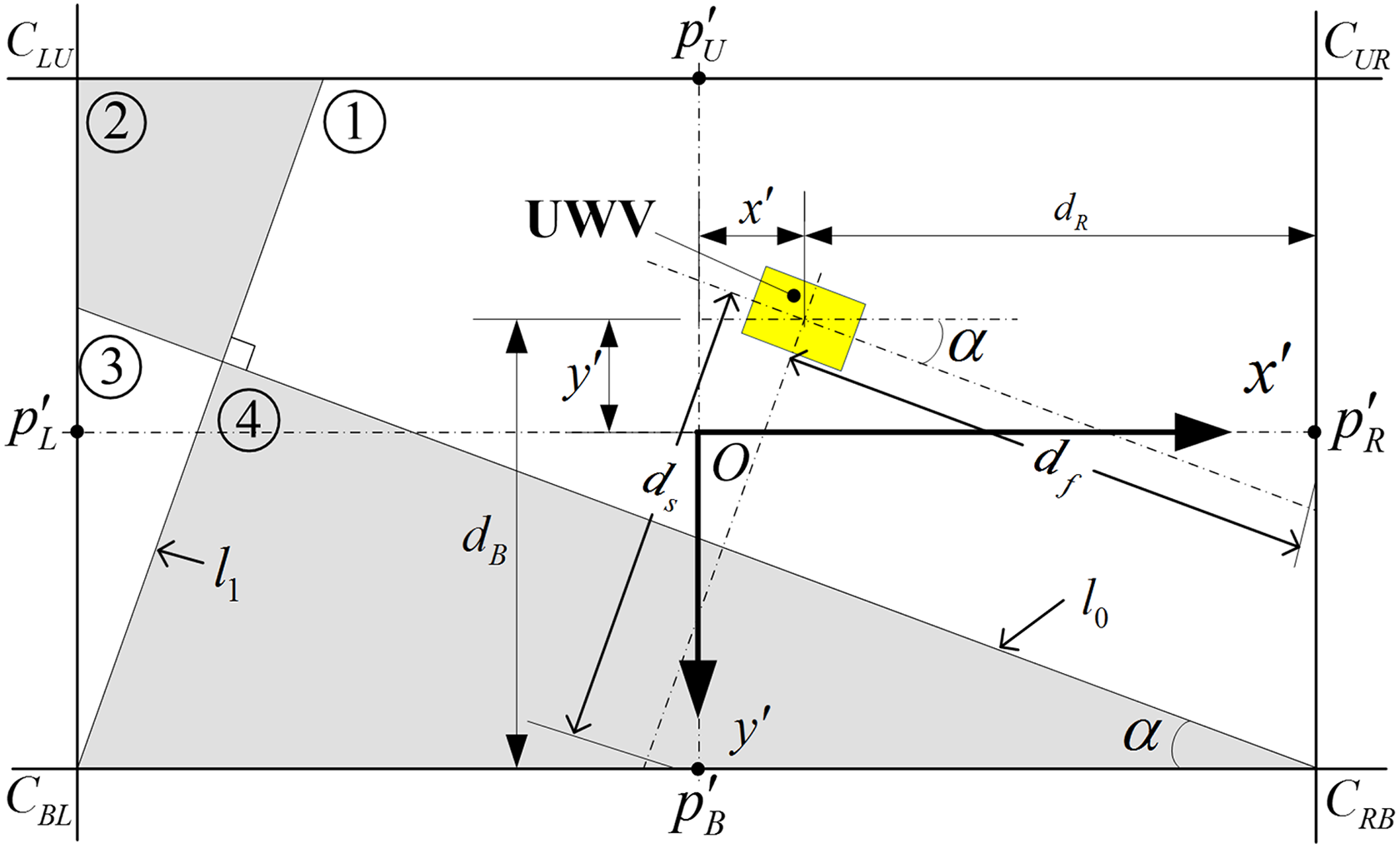
Situation 1: the UWV locates in region 1. df and ds are the data measured by the two altimeters.
If the UWV locates in region 1, the front and the side altimeters’ signals will touch the sides R and B, respectively, as shown in Figure 5. Hence, the coordinate of the UWV in

The situation in region 3 is similar to region 1. The UWV locates in region 3 at time

The front altimeter’s signal will touch the side B and the side altimeter’s signal will touch the side L. So the coordinate of the UWV in

2) The UWV locates in region 2 as shown in Figure 6 at time


Situation 2: the UWV locates in region 2. df and ds are the data measured by the two altimeters.
In region 2, the front altimeter’s signal will touch the side R and the side altimeter’s signal will touch the side L, as shown in Figure 6. The two altimeters’ signals touch parallel planes at the same time, the x′ coordinate is

However, the y′ coordinate is missing. Fortunately, the position and orientation of the UWV at time
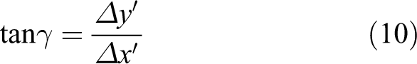
where
Schematic of reckoning. The coordinate of the UWV at time t can be calculated by the coordinate at
Therefore, the y′ coordinate is

The UWV locates in region 4 at time

The situation in region 4 is similar to region 2. Both of the altimeter’s signal will touch the side B. Consequently, the coordinate of the UWV in

Finally, the coordinate of the UWV in

Optimized MRDL algorithm
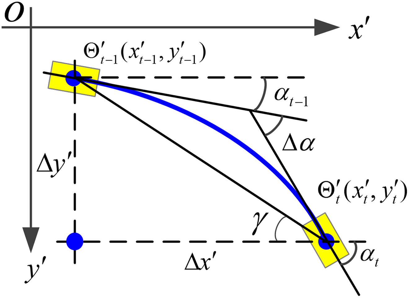
The MRDL algorithm mentioned above only considers the ideal condition under two assumptions: (1) the UWV keeps parallel to the horizontal plane and (2) the emission ultrasonic wave of the underwater altimeter is regarded as radial. However, in practice, the roll angle and pitch angle change all the time, and the beam angle of the altimeter is conical of 6° (
Data correction (DACOR) of the two altimeters
As presented in Figure 8, let ε be the half of the beam angle emitted by the altimeter. Consequently, the direction vector of the front altimeter in

where

where
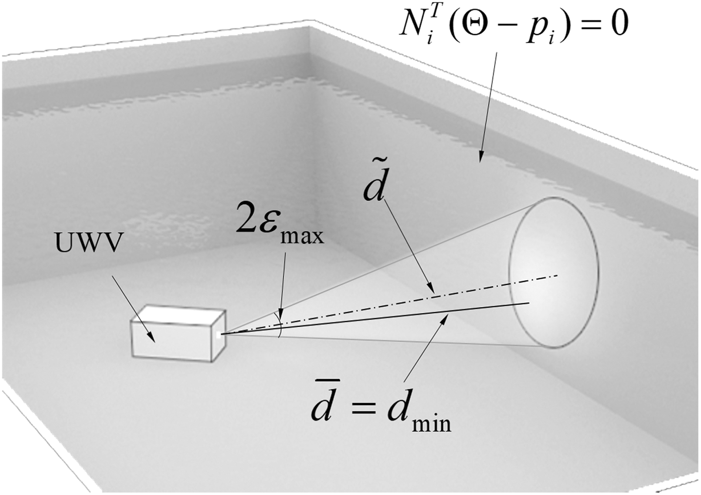
Schematic of the beam angle of altimeters.
The two direction vectors in

where
In MRDL, the side touched by the altimeter can be confirmed by the attitude of the UWV Γ and the coordinate of the UWV

where

So the direction vector of the altimeter’s measurement is

In MRDL, the direction vector of the altimeter

Therefore,
VCF for data fusion
In MRDL, the SFP is divided into four regions according to the angle α between the UWV and axis
Assume that the UWV locates at
As presented in Figure 9, the distance between the UWV and


Boundary effects caused by shouting distance between UWV and each two regions.
Similarly, the distance between the UWV and

When the UWV is close to boundaries, the data measured by the altimeter may be the distance between the UWV and the undesired side due to the beam angle of the altimeters. Therefore, the closer the UWV is to the boundary, the more unreliable the altimeter’s data becomes. Consequently, a confidence coefficient ω is introduced to measure the confidence of the altimeter’s data which is written as

where λ is the factor of convergence rate, σ is the factor of offset, and d is the distance between the UWV and the boundary. The relationship between ω and d is shown in Figure 10.

The evaluation of the confidence of the altimeters’ data. A confidence coefficient ω is introduced to measure the relationship between confidence and d under different λ.
The UWV locates in region 1 or 3 if its coordinate meets equation (4) or (6). In these two regions, the coordinate of the UWV can be calculated not only by substituting the two altimeter’s data into equation (5) or (7) but also by reckoning as

These two localization data can be fused as

where Ω is the confidence matrix
The UWV locates in region 2 or 4 if its coordinate meets equations (8) or (12). In these two regions, the two altimeters’ signals touch parallel planes at the same time. The coordinate can be calculated by each altimeter, respectively, through equations (9) and (13). Consequently, these two localization data can be fused as

where
Simulation results
In order to validate the performance of the proposed algorithm in “MRDL algorithm” and “Optimized MRDL algorithm” sections, computer simulations are performed for localization of UWVs in a confined structured water areas. The dimensions of the SFP are assumed as follows: the length of the pool is L=8 m, the width is W=4 m, and the height is H=5 m. t is the sampling time and
The simulated results of different tracks of the UWV including parallel movement, linear movement, and circular movement are plotted in Figures 11 to 13, respectively. Figures 11(a), 12(a), and 13(a) are the motion trail of three tracks, where the black solid line is the real track of the UWV. The red dotted line and the blue dashed line are the estimated tracks by MRDL and OMRDL, respectively. In order to reveal the accuracy of the two algorithms more visually, the localization errors in direction x of the MRDL and OMRDL are plotted in Figures 11(b), 12(b), and 13(b), and the corresponding results in direction y are plotted in Figures 11(c), 12(c), and 13(c), where the red dotted line expresses the error of MRDL and the blue solid line indicates the error of OMRDL.

Simulated results of moving along a rectangle. (a) Localization results. (b) Errors in direction y. (c) Errors in direction x. The black solid line is the real track of the UWV. The red dotted line and the blue dashed line are the estimated tracks by MRDL and OMRDL, respectively. UWV: underwater welding vehicle; MRDL: multi-regions division localization; OMRDL: optimized MRDL.

Simulated results of moving along an oblique line. (a) Localization results. (b) Errors in direction y. (c) Errors in direction x. The black solid line is the real track of the UWV. The red dotted line and the blue dashed line are the estimated tracks by MRDL and OMRDL, respectively. UWV: underwater welding vehicle; MRDL: multi-regions division localization; OMRDL: optimized MRDL.

Simulated results of moving along a circle. (a) Localization results. (b) Errors in direction y. (c) Errors in direction x. The black solid line is the real track of the UWV. The red dotted line and the blue dashed line are the estimated tracks by MRDL and OMRDL, respectively. UWV: underwater welding vehicle; MRDL: multi-regions division localization; OMRDL: optimized MRDL.
Parallel movement along the four sidewalls of the SFP is the most commonly motion. As presented in Figure 11(a), the two estimated tracks have good performances that they approximately coincide with the real track. The average errors of the two algorithms are 20.04 and 15.23 mm, respectively. As shown in Figure 11(b) and (c), the maximum errors in direction x of the two algorithms are 50 and 27 mm, respectively. Moreover, the maximum errors in direction y are 21 and 13 mm, respectively. Consequently, the OMRDL performs better than the MRDL.
Another common motion is linear movement along arbitrary direction, as presented in Figure 12(a). The average errors of the two algorithms are 72.36 and 49.30 mm, respectively. In Figure 12(b) and (c), large localization errors occur at the beginning due to the information missing in region 2. As the movement of the UWV, the localization errors gradually decrease since the UWV goes into region 1. Moreover, it can be seen through the error curves that the localization error of MRDL is visibly larger than that of OMRDL because of neglecting the beam angle of the altimeters.
Circular movement is the most difficult motions to localize, since both the position and attitude of the UWV vary significantly over time. The MRDL and OMRDL implement the localization of the UWV, although the localization performance of circular movements is not as good as those of parallel and linear movements. As shown in Figure 13(b) and (c), the red dashed line is the localization error of MRDL and the blue solid line is the error of OMRDL. The average errors of the two algorithms are 22.75 and 15.52 mm, respectively. The maximum error of MRDL is caused by the boundary effects as marked with green dashed circle in Figure 13(a). Under those circumstances, the UWV locates in region 2 or 4 and also closely to the region boundary. The large localization error caused by the missing information of x or y coordinate and the inaccurate data of the altimeter can be restrained as the OMRDL takes notice of the boundary effects.
Experimental results
The HITUWV, shown in Figure 14(a), is a tethered, open-frame UWV which developed by Research Center of Aerospace Mechanism and Control at Harbin Institute of Technology. The HITUWV is powered by an isolated 300VDC/8 kW power supply. The mass of the vehicle is 100 kg and it is 1.06 m long, 0.68 m wide, and 0.61 m high. The maximum movement speed of the HITUWV is 0.2 m/s, and the maximum rotational speed of the HITUWV is 0.26 rad/s.

The HITUWV is designed for crack welding automatically in SFPs. (a) The photograph of experimental environment. (b) The appearance of HITUWV. (c) Sensors used in the experiments. UWV: underwater welding vehicle; SFP: spent fuel pool.
As presented in Figure 14(b), the on-board AHRS is MTI-G-700 units with a precision of 0.3°. The two underwater altimeters are ISA500-L with 0.1 120-m range capability and 1-mm acoustic accuracy. The experimental environment is 8 m long, 4 m wide, and 2.5 m high, as shown in Figure 14(c).
The experimental results are presented in Figures 15 to 17. Figures 15(a), 16(a), and 17(a) are the motion trail of three tracks, where the black solid line is the real track of the UWV. The red dotted line and the blue dashed line are the estimated tracks by MRDL and OMRDL, respectively. The localization errors of MRDL and OMRDL are plotted in Figures 15(b), 16(b), and 17(b), where the red dotted line expresses the error of MRDL and the blue solid line indicates the error of OMRDL.

Experimental results of moving along a straight line. (a) Localization results. (b) Localization error. The black solid line is the real track of the UWV. The red dotted line and the blue dashed line are the estimated tracks by MRDL and OMRDL, respectively. UWV: underwater welding vehicle; MRDL: multi-regions division localization; OMRDL: optimized MRDL.

Experimental results of moving along an oblique line. (a) Localization results. (b) Localization error. The black solid line is the real track of the UWV. The red dotted line and the blue dashed line are the estimated tracks by MRDL and OMRDL, respectively. UWV: underwater welding vehicle; MRDL: multi-regions division localization; OMRDL: optimized MRDL.

Experimental results of moving along an arc. (a) Localization results. (b) Localization error. The black solid line is the real track of the UWV. The red dotted line and the blue dashed line are the estimated tracks by MRDL and OMRDL, respectively. UWV: underwater welding vehicle; MRDL: multi-regions division localization; OMRDL: optimized MRDL.
As sketched in Figures 15 and 16, it can be seen that the experimental results are in good agreement with the simulated results. Both MRDL and OMRDL hold good performances along a straight line and an oblique line, respectively. The maximum error of the OMRDL is about 45 mm, indicating higher location accuracy than MRDL, as shown in Figures 15(b) and 16(b). Furthermore, the OMRDL has a better depression on sensors’ error caused by getting close to the sidewalls.
The localization results of the UWV moving along an arc are the worst for both MRDL and OMRDL. However, in the cases where the UWV moves along an arc, the maximum error for the OMRDL is 87 mm, which is much smaller than that of 156 mm for the MRDL. With the movement of the UWV, it will fall into regions 4 and 2 where the two altimeters’ signals touched the same planes at the same time. During that time, the MRDL caused significant errors due to the loss of localization information. Fortunately, the OMRDL showed great localization performance in such extreme circumstances due to the consideration of the error caused by the UWV’s orientation and the altimeters’ beam angle. Moreover, the VCF fuses the localization data calculated by different regions and decreases the error caused by boundary effects.
Conclusion
This article presented a novel approach for general UWVs’ localization in confined water area via AHRS and altimeters. The coordinate of the UWV was obtained by fusing the data of AHRS and two altimeters. The MRDL algorithm was introduced for the first time where the SFP is divided into multi-regions and different processing methods are used for different regions. Moreover, considering changes of the UWV’s orientation, beam angles of the altimeters, and the boundary effects, an optimized MRDL algorithm (i.e. the OMRDL) was proposed which utilizes DACOR and VCF for localization error reduction. Simulated and experimental results demonstrated that the MRDL and OMRDL performed well with localization accuracies of 160 and 90 mm, respectively, which were good enough for localizing UWVs in SFPs. Furthermore, the OMRDL demonstrated higher location accuracy than MRDL in all cases. In the future work, the localization approach will continue to be optimized to make it capable of rejecting the interference caused by uncertain obstacles.
Footnotes
Acknowledgement
The authors would thank the reviewers and editors for their constructive comments and suggestions, which have been valuable to improve this article.
Declaration of conflicting interests
The author(s) declared no potential conflicts of interest with respect to the research, authorship, and/or publication of this article.
Funding
The author(s) disclosed receipt of the following financial support for the research, authorship, and/or publication of this article: This work was supported by National Natural Science Foundation of China (Grant No.61673138) and National Key Basic Research Development Plan Project (973) (2013CB035502).