
Abstract
The aerial manipulator has recently attracted much research attention due to its wide applications such as aerial cleaning, aerial transportation, and aerial manipulation. It is important to design a reliable controller for the aerial manipulator to robustly perform aerial tasks with different settings. However, current controllers still employ manual parameters tuning methods, which is mostly limited to a specific setting like a fixed aerial manipulator configuration or an unchanged environment. In fact, there could be diverse configurations of aerial manipulators and uncertain environments in practice, which requires the manual tuning process to be frequently repeated. This repetition is easy to be unavailable due to its significant cost of time and expensive involvements of control-tuning experts. To solve these problems, a novel multi-objective-optimization-based control parameters auto-tuning method is proposed for the aerial manipulator. Based on a conventional proportional–integral–derivative control structure, an evolutionary-algorithm-based optimization is used to automatically find optimal proportional–integral–derivative control parameters to satisfy conflicting objectives such as minimizing the integrated time square error and the control rate. Simulation results prove that the proposed method can achieve better control performances like smaller overshoots and faster stabilization time than manual tuning methods.
Introduction
Thanks to the physical interactions with surrounding environments, the capacities of unmanned aerial vehicles (UAVs) have been extended from “passive” tasks such as inspection, 1 remote sensing, 2 and surveillance 3 to “active” tasks like aerial manipulation. 4 –20 Although many tools including grippers, 4,5 cables, 6 –9 screw drivers, 10 and brushes 11 have been used for the important physical interactions, attaching a robotic arm to a UAV, named an aerial manipulator, 12 –20 has lately been considered as the most efficient and promising way. The aerial manipulator does not restrict the attitude of the payload or the reachable space of the end-effector as a stationary gripper-based platform does. It is also able to directly regulate the movement of the payload, of which the cable-based platform is not capable.
It is important to design a reliable controller for the aerial manipulator to robustly and accurately finish tasks. Some such controllers have been reported for different tasks. For example, a Cartesian impedance controller
12
was proposed for a quadrotor equipped with a three-degree-of-freedom (3-DOF) robotic arm to execute dexterous manipulation tasks. A novel hierarchical motion control scheme,
13
including a top layer of an inverse kinematics algorithm and a bottom layer of a motion control algorithm, was introduced for a quadrotor with a 5-DOF robotic arm to follow circular helix trajectories. A sliding mode controller
14
was designed to transport objects using a quadrotor with a 2-DOF robotic arm. For the Aerial Robotics Cooperative Assembly System (ARCAS) project, a multilayer control architecture,
15
including a novel battery movement compensation, arm static compensation, and external generalized forces estimation and compensation, was proposed for an octorotor with a 6-DOF robotic arm. To allow outdoor operations, a stable backstepping-based controller and an admittance controller were developed for an octorotor and its 7-DOF robotic arm, respectively.
16
To fly with unknown objects, an augmented passivity-based controller
17
was designed for a hexacopter with a 2-DOF robotic arm by online estimating unknown parameters of the payload. The attitude control of a hexacopter equipped with a 2-DOF robotic arm was achieved by a quaternion-based backstepping method.
18
A variable parameter integral backstepping controller
19
was presented for an unmanned helicopter equipped with multi-link arms to perform structure assembly and manipulation tasks. An advanced controller, including an attitude and a rate command augmentation system, a feedforward torque compensation system, and an
However, these controllers employed manual tuning of control parameters, which may severely hinder their applications in practice. One reason is that the robot configuration or the environment is not always unchanged in practice. As a well-tuned control parameter set is generally tuned for a specific dynamic model case, the practical time-varying dynamics could easily make the current controller no longer suitable. To address this problem, the manual tuning needs to be frequently repeated; however, it requires a large amount of time like days and expert knowledge. In addition, practical applications often require the controller to satisfy multiple but often conflicting goals like both a good task accuracy and a short completion time. This is much more difficult for the manual tuning compared with satisfying only one single objective. Even if the previous requirements are all achievable and acceptable, the manual tuning could be still difficult or even impossible due to human’s own limit, named bounded rationality, 21,22 in handling complex systems. For example, humans need to tune 27 parameters for a 6-DOF quadrotor equipped with a 3-DOFs robotic arm using a proportional–integral–derivative (PID) controller; however, the bounded rationality argues that humans begin to struggle when four variables are involved in problem solving and more than five variables to be solved at the same time nearly impossible.
One way to solve the manual tuning problems is automatically tuning parameters based on multi-objective optimization (MOO), and its effectiveness has been proven by other practical applications such as automatic voltage regulator system, 23 chemical titration and neutralization plant, 24 and linear brushless direct current (DC) motor. 25 Although the optimization of gains control is not a new idea, it has never been studied for aerial manipulators. As a useful tool for practical aerial tasks, it is meaningful to formulize the specific MOO-based auto-tuning method for the aerial manipulator and validate its feasibility since the aerial manipulator is much more complex than previous systems. 23 –25 Thus, we propose a new MOO-based control parameters auto-tuning method for the complex aerial manipulator system with specific problem formulizations. It is tested in two conventional parallel PID controllers that are designed for motion controls of a quadrotor and a 3-DOF robotic arm, respectively. Although the PID controller is basic and simple, it is proved to be useful with good performances in practical applications. For each PID controller, an evolutionary algorithm-based optimization, Non-Dominated Sorting in Genetic Algorithms (NSGA)-II, is used to automatically find optimal control parameters, avoiding the time-consuming manual tuning process. Two conflicting objectives, reliable static–dynamic performance and smooth control, are considered as an example of possibly conflicting performance criteria. The main contributions are considered as (1) the work provides a new MOO-based automatic parameters tuning to stably control the highly nonlinear and complex aerial manipulator system with possible dynamic changes in many different situations. (2) This method can be easily transferred to similar aerial manipulators with different UAVs and robotic arms using any controllers. This work does not need structure modifications or additional mechanical designs, 15 as the problem is fully solved through the control algorithms. (3) This work investigates meanings of multiple equivalent optimal solutions, as well as the consequences of adding new objectives. This could be used as a starting point for users to better understand how to select an appropriate set of control parameters according to their own requirements.
Modeling
As the aerial manipulator modeling is based on a fundamental but common Euler–Lagrange method, we only explain necessary kinematic and dynamic models, which have been studied in previous works, 12 –14,16 –18 for the following controller design.
Kinematics for the quadrotor–arm system
With the aerial manipulator system consisting of a quadrotor and a robotic arm shown in Figure 1,

Coordinate configuration of the aerial manipulator system.

where
The relationship between the velocities in different frames is given as follows


where
Let


For simplicity, equations (2), (4), (7), and (8) can be rewritten in the following matrix form 14


where the subscript
Dynamics for the quadrotor–arm system
Given the Euler–Lagrange method provides an easy way to derive the system dynamics, the following Lagrange-D’ Alembert equation is used


where
The total kinetic energy is contributed by the quadrotor and each individual link, so the total kinetic energy
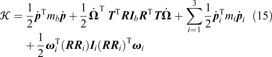
where m is the mass and
Similarly, the total potential energy is contributed by the potential energy of the quadrotor and each link, which is described by the equation below
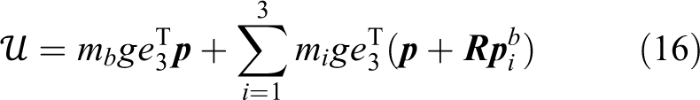
where the first and last terms are the potential energies of the quadrotor and link i, respectively.
By computing equation (13) and considering the Christoffel symbols of the first type, 26 the dynamics equation which includes all components as one system can be derived as the following

where
The input vectors

where
The matrices
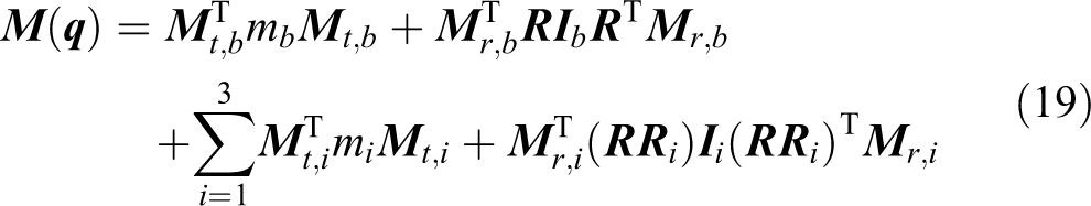


where
MOO-based PID control scheme
This section focuses on explaining the MOO-based auto-tuning method with conventional PID control designs. The combination of the PID controller and parameters auto-tuning method results in the MOO-based PID control method for aerial manipulators.
PID control structure for the aerial manipulator
Since we only discuss the stabilization of the aerial manipulator system in this article, the external disturbance/force in equation (17) is assumed to be zero. This assumption will not affect the validness of the proposed method because the external disturbance/force term can be moved to the left side of equation (17), which makes the design of control input

where the auxiliary input σ can be partitioned, according to equation (1), that is,

Because

where
MOO-based PID control parameters auto-tuning
As shown in Figure 2, the multi-objective evolutionary algorithm (MOEA) is used to automatically tune the PID control parameters. The integration of parameters auto-tuning process and the PID controller results in the MOO-based PID controller for aerial manipulators. This controller includes two PID control loops. One is for the quadrotor and another one is for the robotic arm. Each PID controller has a set of control parameters. Because the quadrotor has six specific variables, the quadrotor PID controller includes a set of (6 × 3) parameters. Similarly, the robotic arm PID controller contains a set of (3 × 3) parameters. Based on the difference between the desired and actual motions as well as the difference between current and previous control inputs, the MOEA finds optimal parameters to meet different criteria. Among all the MOEAs, we select the improved NSGA-II 30 as the specific optimization algorithm due to its efficiency and the ease to be implemented in practical applications. While traditional optimization methods convert the MOO to single-objective problems by emphasizing one particular Pareto-optimal solution at a time and running many times, the NSGA-II algorithm is more efficient because its evolutionary mechanism can find multiple Pareto-optimal solutions in one single run. Compared with other popular evolutionary algorithms developed in the same time period such as Pareto-archived evolution strategy (PAES) 31 and strength-Pareto evolutionary algorithm (SPEA) 32 and the original NSGA, 33 NSGA-II has an outperforming performance in terms of finding a diverse set of solutions and in converging near the true Pareto-optimal set because it has a better sorting algorithm and incorporates elitism. It has also been proved to be easily implemented in practical problems like generation expansion planning, 34 water resources management, 35 and distributed hydrologic modeling 36 with good results. Due to the complexity of the aerial manipulator system, the auto-tuning process based on NSGA-II is off-line as the inside evolutionary scheme costs considerable time like minutes or hours to find optima. In this work, it takes 30 minutes to find the optimal PID parameters.

MOO-based PID control structure for the quadrotor-arm system. MOO: multi-objective-optimization; PID: proportional–integral–derivative.
Two objectives are considered for the NSGA-II algorithm. One is the reliable static–dynamic performance, and the other is the smooth control. Both these two objectives are important for the aerial manipulator system to keep stability, but they cannot be achieved simultaneously because they conflict with each other. In general, seeking for some dynamic specifications usually causes the large variance of control law and significant oscillating of the actuators. The performance balance between these two objectives will be discussed in the next section. The reliable static–dynamic performance is represented by


where
Numerical simulations
Simulation setup
In this work, all simulations are completed in MATLAB/Simulink [version R2015b]. The parameters of the aerial manipulator system 12 are listed in Table 1.
Quadrotor simulation parameters.

The parameters of NSGA-II algorithm are listed in Table 2. As mentioned before, the lower bound LB and upper bound UB should be vectors corresponding to each control variable. Because we consider all the boundary values to be the same, there is only one value in Table 2, for simplicity. In fact, the bounds of the gain parameters may be difficult to be determined beforehand in practical situations. They are assigned values here only for a convenient calculation and can be practically expanded to a larger value to include more possible solutions. Other NSGA-II-related parameters are empirically chosen.
Parameters used for NSGA-II.

NSGA-II: Non-Dominated Sorting in Genetic Algorithms-II.
To compare the performance of different PID parameters, the quadrotor performs a basic but important action within the aerial manipulation. Specifically, the quadrotor is supposed to follow a planar and circular trajectory:

Visualization of simulated movements. The quadrotor is designed to follow a circular trajectory. The arm is designed to move from configuration A to configuration B when the quadrotor starts flying.
In the next section, we will show a comparison between results using manual-tuned parameters (such as using Ziegler–Nichols method 37 ) and auto-tuned parameters. To further discuss the performance of the automatic tuning method, we will also provide the simulation results of a state-of-the-art control method, model predictive control (MPC). MPC is an advanced process control method which calculates the future state of the system and organizes the control action accordingly. It predicts the future of the system and sends control signals in such a manner that it reduces a cost function defined as the error between the output and the desired tracking point over a particular prediction horizon. 38 It has been proven in many complex systems 38 –41 to provide better performances, especially stronger robustness against uncertainties, than a majority of current control methods like PID control and sliding mode control. Two key parameters, the control horizon (M) and the prediction horizon (N), are both chosen to be 10 in this article.
Simulation results
The necessity of automatic tuning
The performances of several different sets of manual-tuned PID parameters are shown in Table 3. The dynamic responses for different PID parameter sets are totally different. For example, the overshoot of link 1 for parameter set 1 is 4.4° less than set 2, but the stabilization time of link 1 is 4.3 s longer than set 2. This makes sense because the overshoot usually behaves inversely with respect to the stabilization time. If we want the aerial manipulator system to stabilize quickly, we need to have a larger control output during the beginning phase, which leads to a larger overshoot. This makes it difficult to judge which parameter set is better because each application has a specific requirement. Just for an illustration, we will consider the less overshoot of links as a better performance in the remaining article. Due to a careful manual tuning by experts, the performances of set 3 and set 4 are much better than set 1 and set 2. Considering the link’s overshoot, set 4 is the best in all the four sets.
Manually tuned PID parameter values and corresponding performances.a

PID: proportional–integral–derivative.
aEach link length L = 0.1 m, each link mass m = 0.1 kg.
If we change the values of arm length and mass to be
PID parameter values and corresponding performances for different arm settings.b

PID: proportional–integral–derivative.
bEach link length L = 0.05 m, each link mass m = 0.05 kg.
The results from both Tables 3 and 4 show the importance and necessity of good tuning of PID control parameters. The well-tuned parameters lead to better control performances, generally satisfying the goals of each task. The major drawback of manual tuning is the time-consuming involvement of humans, which could be unacceptable in practical applications. Hence, it is necessary and convenient for the controller to have a set of automatically tuned parameters, adapting to different environments and systematical uncertainties.
Performance evaluation of MOO-based PID control
In this article, auto-tuning is achieved using MOO, NSGA-II. In fact, there are multiple sets of PID parameters that are obtained by NSGA-II. The set of these solutions, called the Pareto front, 42 can be seen in Figure 4. All these solutions are regarded as optimal because all of them satisfy the two objectives simultaneously and no objective can be improved without sacrificing the other objective. The differences between solutions indicate various trade-offs between the objectives.

Pareto front for MOO in terms of integrated time square error and control rate. The solutions to the left of point A focus more on minimizing the integrated time square error while the solutions to the right of point B focus more on minimizing the control rate. The solutions between points A and B are more balanced between the integrated time square error and control rate. MOO: multi-objective-optimization.
The two axes of Figure 4 are two objectives,
Due to the trade-offs between two objectives in the Pareto front, the dynamic responses of each solution are totally different. For simplicity, we randomly pick two solutions between points A and B out of all the solutions to analyze their performances. The performance comparison can be seen in Table 5. Link 1’s overshoot using parameter set 6 is zero, which is better than set 5’s 1.6°. However, the stabilization time for link 1 using set 6 is 1.3 s longer than set 5. The conflicts and trade-offs can give users some suggestions on selecting the most suitable parameters. If users focus more on the control smoothness, then parameter sets close to point B in Figure 4 are recommended. If the integrated time square error is more important, then parameter sets close to point A are suggested.
Performances of auto-tuned PID parameter sets 5 and 6.

Performance comparison between manual-tuning, auto-tuning, and MPC
For convenience, we directly use the auto-tuned PID parameter set 5 in Table 5 to compare its performances with those of other different control methods. The performance comparison between the auto-tuned parameter set 5 and manual-tuned parameter set (e.g. set 1 and set 4 in Table 3) is shown in Table 6. Also, as mentioned at the end of simulation setup, we add the MPC simulation results in Table 6 for comparison. Additionally, Figure 5 is presented to show the change of joint angles using PID parameter set 1, set 4, set 5, and MPC. Correspondingly, Figure 6 shows the quadrotor trajectories. Figure 7 uses a bar plot to present a more intuitive comparison of various system responses in Table 6. This case uses the original aerial manipulator system parameters in Table 1.

Link performance comparison using PID parameter set 1 (manual-tuned), 4 (best manual-tuned), 5 (auto-tuned), and MPC. The auto-tuned performances are comparable to MPC because the differences between the red solid lines and green dashed–dotted lines are small. Although the best manual-tuned performances (purple dotted lines) are close to auto-tuned and MPC performances for links 2 and 3, the best manual-tuned link 1 performance is notably worse than the auto-tuned and MPC performance. The manual-tuned performances (blue dashed lines) are worst with significant oscillations. PID: proportional–integral–derivative; MPC: model predictive control.

Quadrotor trajectories using PID parameter set 1 (manual-tuned), 4 (best manual-tuned), 5 (auto-tuned), and MPC. The auto-tuned parameter set 5 has comparable performances with MPC, but better performances than manual tuned parameter sets in terms of less deviations and faster stabilization time. PID: proportional–integral–derivative; MPC: model predictive control.

Performance comparison of PID parameter set 1 (manual-tuned), 4 (best manual-tuned), 5 (auto-tuned), and MPC. All performances including the overshoot, stabilization time, quadrotor position deviation, and quadrotor angle deviation are considered better with smaller values. The auto-tuned and MPC performances are comparable while they are better than the manual-tuned performances. PID: proportional–integral–derivative; MPC: model predictive control.
Performance comparison of PID parameter set 1 (manual-tuned), 4 (best manual-tuned), 5 (auto-tuned), and MPC.

MPC: model predictive control; PID: proportional–integral–derivative.
It is worthy to notice that all the performances of parameter set 5 are better than set 1, as the optimization method is used. It can be seen in Figure 5 that there are less oscillations of parameter set 5 than set 1. This means the changes of control inputs are less and smoother, meeting objective
Since there may be more than two objectives in practical applications, we also simulate a case with three objectives by adding a new one specifying no overshoot for the link 1 joint angle. Similar to the two-objective case, there is also a Pareto front with numerous solutions. For convenience, we picked out a solution that happens to be the same with parameter set 6 in Table 5. It does not have an overshoot for link 1’s joint angle, which is verified to meet the newly added objective. However, the three-objective optimization needs a longer tuning time for the whole simulation, which is about three times than the time used for the two-objective case. This indicates that we can add more and new objectives into the MOO-based PID control formulation, that is, equation (25), but the feasible number of objectives may have an upper limit due to the additional computational complexity. MPC needs much more time than MOO-based PID if adding new objectives due to its own high complexity, which sometimes limits its practical application. Also, the PID controller is most widely used controller in the industry, and it may be easier and more convenient to keep the PID structure unchanged rather than developing a new and complex MPC controller.
Conclusion
In this article, we present a MOO-based control parameters auto-tuning method for the aerial manipulator system to be better applied in practical applications. This method uses NSGA-II, an MOEA, to automatically find optimal parameters for different control goals that are related to the desired and actual measurements of the aerial manipulator system. The auto-tuning performances are comparable to a well-designed state-of-the-art model predictive controller while both are better than manual-tuned performances.
The reasons about the better performances of auto-tuned controllers can be concluded as (1) the flexibility to changing conditions and (2) inherent satisfaction of multiple objectives. The practical changing conditions (including both robot dynamics and task environments) easily make current manual-tuned controllers that are designed for specific configurations or tasks not suitable. In contrast, the auto-tuning method has more flexibilities to these changes due to the inside optimization mechanism. Even for the case that humans can tune parameters for each situation, although this is nearly impossible, it costs significantly more time than the auto-tuning method. Furthermore, it is sometimes extremely difficult for even experts to tune appropriate parameters for multiple control objectives. Humans may not be able to quantitatively and precisely balance between different control objectives due to human’s fuzzy logic and approximate reasoning. Instead, the auto-tuning method can use an exact mathematical form to accurately evaluate trade-offs between different objectives. Compared with the advanced MPC, the MOO-based auto-tuning method is easier to be implemented and extended due to less computational complexity and more flexibility to add additional objectives.
Although the proposed MOO-based auto-tuning method is an off-line method, it can still be applied to many practical applications that require relatively less time sensitivity. If the aerial manipulator is used to transport different loads in different tasks, for example, then this auto-tuning method could be more efficient than a manual-tuned aerial manipulator to adapt to a specific load. Moreover, there could be different combinations of UAVs and robotic arms to generate an aerial manipulator system. It will be easier to use the auto-tuning method to handle such a large variety.
Despite the advantages, the MOO-based auto-tuning method can still be improved. For example, it is worth investigating how to select the best solution from the Pareto-front. This may be solved using graphic methods to visualize the distribution of solutions in Pareto-front. It could be especially useful when the solution dimension is high. When the number of objectives becomes more than three, the complexity of MOO greatly increases and hence the efficiency correspondingly decreases. It may be necessary to find another efficient optimization algorithm for this problem. We also plan to conduct experiments on real aerial manipulators to see how the presented method works with unavoidable noises.
Footnotes
Declaration of conflicting interests
The author(s) declared no potential conflicts of interest with respect to the research, authorship, and/or publication of this article.
Funding
The author(s) received no financial support for the research, authorship, and/or publication of this article.