
Abstract
This article presents a model-based velocity controller able to induce a chaotic motion on n-degrees of freedom flexible joint robot manipulators. The proposed controller allows the velocity link vector of a robot manipulator to track an arbitrary, chaotic reference vector field. A rigorous theoretical analysis based on Lyapunov’s theory is used to prove the asymptotic stability of the tracking error signals when using the proposed controller, which implies that a chaotic motion is induced to the robotic system. Experimental results are provided using a flexible joint robot manipulator of two degrees of freedom. Finally, by using Poincaré maps and Lyapunov exponents, it is shown that the behavior exhibited by the robot joint positions is chaotic.
Introduction
Overview
Typically, rigid-link robot manipulators do not reflect a real scenario when a high performance is required. If the robot moves at high velocities or interacts with the environment, some deflections may occur in the robot components, inducing vibration to the robot. Undesired vibrations may occur by the joint flexibility, which is caused by elasticity of motion transmission elements, such as harmonic drives, belts, or long shafts. 1
Some applications of robot manipulators where joint flexibility occurs include compliant manipulation in contact with a human environment, requiring the robot to have low reflected inertia and high accuracy in force control, 2 which may be accomplished by increasing the joint flexibility of the robot manipulator. 3 Besides, the mass of flexible joint robot (FJR) manipulators is smaller than that of rigid robots. This feature allows them to move faster, while consuming a less amount of energy.
The term chaos is used to describe a nonperiodic and outwardly random behavior that happens in some nonlinear dynamic deterministic systems. Such a behavior exists because these nonlinear systems have 4 –6 high sensitivity to initial conditions (the butterfly effect 7 ), that is, neighboring states diverge as time proceeds; topological transitivity, that is, every non-empty open subset of the phase space is traveled by the trajectory originating from an arbitrary open subset; and denseness of periodic orbits, which yields a broad frequency spectrum.
There exists a large variety of applications in science and engineering where chaos can be beneficial. Some of them include applications in medicine and electronics. Other important applications are mixing of fluids and granular flows by inducing a chaotic motion on direct current (DC) motors and rigid-link robot manipulators, path planning for mobile robots, vibration control of FJR manipulators, parameter identification, motion control, manufacturing human-like robots, bipedal walking, among others. 8 –16 Therefore, the problem of inducing a chaotic motion to an FJR manipulator is an important issue that deserves to be studied.
Although the number of applications where the existence of chaos is required is increasing, there are a few works presenting methodologies for inducing a chaotic behavior in robot manipulators. In addition, the existing literature only considers applications on rigid-link robot manipulators or FJR manipulators of 1-degree of freedom (DOF). It is also worth noting that for a general n-DOF FJR manipulator the control task increases its complexity because the number of DOF is enlarged twice with respect to the DOF of a rigid-link robot manipulator. Hence, in order to contribute to this field in a more realistic way, this work presents a model-based velocity controller that allows inducing a chaotic motion on FJR manipulators of n-DOF. Furthermore, the proposed controller is validated through experimental results using a 2-DOF FJR manipulator.
Literature review
The mathematical model describing the dynamics of an FJR manipulator is important for the control synthesis. It is well known that the general dynamic model of an FJR manipulator may not satisfy neither the necessary conditions for input–output decoupling nor those for full linearization by static state feedback. 17 Instead, dynamic state feedback controllers can be employed to linearize the system, because FJRs are input–output invertible systems with stable zero dynamics. 18 On the other hand, a simplified model, which assumes that the angular part of the kinetic energy of each rotor is due only to its own rotation, can be used. 19 The advantage of using a simplified model is that it is globally feedback linearizable by static state feedback. Finally, note that many robust control techniques such as sliding modes can be used to control rigid n-link robot manipulators. 20 However, the performance of such methodologies worsens when the joint flexibility is not negligible.
Methodologies for controlling FJR manipulators include state feedback controllers, 21 passivity-based impedance control, 22,23 adaptive techniques, 24,25 sliding mode control (SMC), 26,27 adaptive SMC, 28 terminal SMC, 29 among others. Besides, an interesting survey on the control of FJR manipulators is presented in Ozgoli and Taghirad. 30
Chaotic systems can be present and used in many areas including biological, electrical and mechanical sciences, control and synchronization, parameter identification and applications involving robot manipulators. 5,6,8 –16 Thus, it evolved a field of study known as chaotization, chaos synthesis or chaos anti-control, which aims to establish a desired chaotic behavior in an otherwise non-chaotic system, or to enhance the chaos of a chaotic system.
It is important to remark that the concepts of tracking, synchronization, and chaotization seem to be similar. Hence, it is useful to distinguish each from the others. To this end, let y(t) and
Chaotization for mechanical systems can be accomplished by means of several methods including proportional derivative control, 34 saturated proportional control, 35 time-delay feedback control applied to DC motors for industrial mixing, 36 chaotization of brushless DC motor systems, 37 –39 adaptive techniques for rigid robot manipulators, 40 feedback linearization for mobile robots, 41 proportional integral derivative control, 42 neural networks, 43 path planning generators for autonomous robots, 44 –46 mechanism synthesis, 47 computing robot kinematics, 48 parameter identification, 49 passive dynamic walking, 50 among others. There are also some studies showing the importance of chaotization in FJR manipulators. In a study by Kandroodi et al., 51 chaotization was used to achieve trajectory tracking and vibration control of an FJR manipulator. Similar procedures for vibration suppression in FJR manipulators have been studied using a variable structure control, 52 a Lyapunov ruled-based fuzzy approach, 53 feedback linearization, 54 a Lyapunov-based approach, 55 and neural networks. 56 Finally, Singh et al. 57 studied a 1-DOF FJR to show the occurrence of various chaotic behaviors.
The previous literature review shows the importance of inducing a chaotic behavior in non-chaotic systems. However, the aforementioned works only consider the chaotification of rigid-link robotic manipulators, or present methodologies that can be applied to 1-DOF FJR manipulators.
Contribution of the article
This work proposes a model-based velocity controller applied to an n-DOF FJR manipulator. An extended system is created by combining the dynamic model of the FJR manipulator and an arbitrary chaotic system. Then, it is theoretically shown that a chaotic behavior is generated on the robotic system when using the proposed controller.
A rigorous stability analysis based on a strict Lyapunov function demonstrates the asymptotic stability of all the tracking error signals. Finally, the proposed chaotification technique is validated in an experimental setup, which consists of a 2-DOF FJR manipulator from Quanser (Quanser Consulting, Markham, ON, Canada).
From the previous literature review, we concluded that the existing work in chaotification of robot manipulators has been focused on rigid-link manipulators or 1-DOF FJR manipulators. Hence, this article contributes by extending the existing results to a more realistic scenario, where the chaotification problem is solved for a general n-DOF robot manipulator where the manipulator joint flexibility is taken into account.
The main contributions of this article are: developing a chaotification methodology that can be applied to an n-DOF FJR manipulator; and presenting experimental results corroborating the validity of the proposed scheme.
Organization
The rest of the article is structured as follows. The system description and problem formulation are stated in the second section. The model-based velocity controller design, which accomplishes the chaotization goal, and its Lyapunov stability proof are presented in the third section. The fourth section is devoted to the experimental validation of the proposed chaotization methodology, using a Quanser 2-DOF FJR manipulator. Finally, some concluding remarks are given in the fifth section.
Notation
Let ℝ denote the set of real numbers, ℕ represents the natural numbers, ‖⋅‖ refers to the Euclidean norm of a given vector or matrix, and |⋅| denotes the absolute value of its argument. In general, vectors are given by bold lowercase letters and matrices are represented by uppercase letters;
System description and problem formulation
The proposed chaotization procedure is applied to n-DOF FJR manipulators, that is, robots with rigid links but with elastic transmissions, where the flexibility is concentrated at the joints. In the following, the dynamic model of an n-DOF FJR manipulator is given. Then, the problem formulation for its chaotization is stated.
Dynamic model of the FJR
Let us consider an FJR manipulator of n-DOF, with rotational joints actuated by DC motors. It is assumed that linear torsional springs, with stiffness constants
A schematic representation of an n-DOF FJR manipulator is depicted in Figure 1. In this figure, each rotor is coupled to the link by means of a torsional spring. Variable qi,
The dynamic equations of an FJR manipulator are given by 19,59,60


with


Schematic representation of an n-DOF FJR manipulator. DOF: degree of freedom; FJR: flexible joint robot.
In equations (1) and (2),
Remark 1
The discontinuous function

in
In the next development, it is assumed that position and velocity measurements of robot joints as well as links are available for feedback.
Chaotic velocity field and extended system
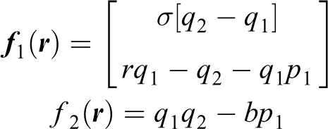
Let us consider a chaotic system described by the next autonomous system
with

where the parameters σ and r are the Prandtl and the Rayleigh numbers, respectively. A chaotic behaviour is obtained by using
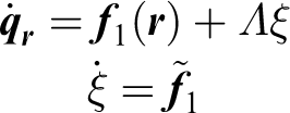
Let us define the extended vector

with

with

Chaotic attractor of the Lorenz system (equation (6)) under the parameters
By considering the chaotic system (equation (5)) and the extended system (equation (8)), the state

To clarify the previous development, let us consider a 2-DOF FJR manipulator. Then, the link position vector is

with
Note that the dimension of the extended vector
Problem formulation
The aim of this work is to show that by means of a model-based velocity controller a chaotic motion is induced to the link position vector of an n-DOF FJR manipulator. Then, this chaotification problem can be formulated as follows.
Control problem
Find a control law

where

is the chaotization error.
Chaotification of the FJR
This section shows how to design a control law

Schematic representation of the proposed chaotization scheme for an n-DOF FJR manipulator. DOF: degree of freedom; FJR: flexible joint robot.
Controller design
In order to decouple the rotor dynamics (equation (2)) from the system (equation (1)), let us consider the controller

where
By substituting equation (12) into equation (2), the next closed-loop equation is obtained

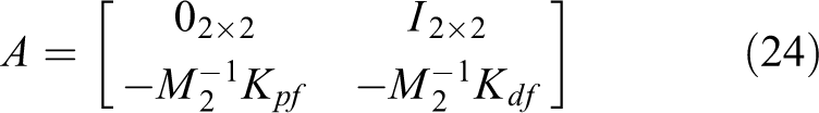
which can be written in state-space form as follows

Notice that the system (equation (14)) is linear with respect to variables
The next step in the control design consists of proving that, when

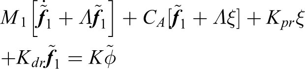
The controller

where

and
The controller
Note that

Then, by using equations (11), (15), and (17), the rigid robot dynamics (equation (1)) can be written as follows
which yields

Using equations (14), (17), and (18), the overall closed-loop system can be written as the next first-order system

Note that
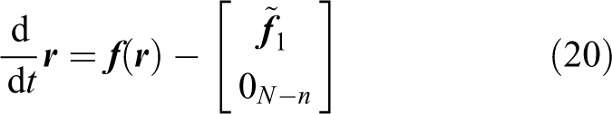
Thus, the asymptotic stability of the state-space origin of system (equation (19)) implies that the chaotification objective given in equation (10) is accomplished.
Stability analysis
To prove the stability of the origin of equation (19), let us consider the Lyapunov candidate function
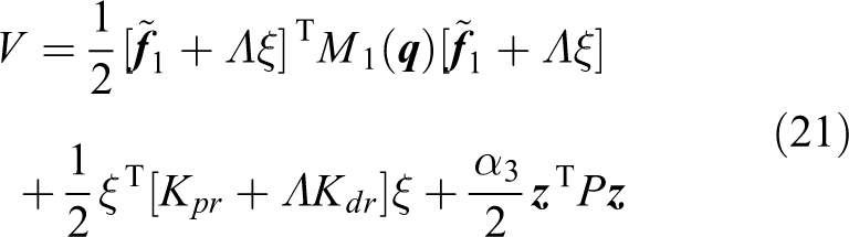
where

and P is a
with
By virtue that
By considering that

where the skew symmetry property that relates
By using equations (19) and (22), the system

is obtained. Thus, substitution of equation (26) into equation (25) yields

where

with

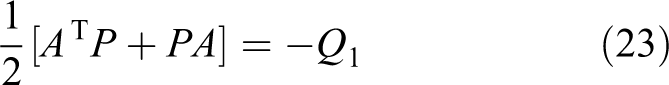
Let us define
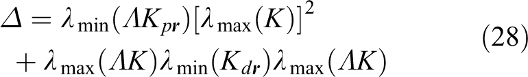
Then, a sufficient condition for the matrix Q2 to be positive definite is that the inequality

holds, which is always possible because α3 can be chosen arbitrarily. Then, by assuming that condition (equation (29)) is fulfilled, it can be concluded that

is satisfied for any initial condition.
The next proposition summarizes the previous development and provides the equations of the proposed model-based velocity controller for the chaotization of a general n-DOF FJR manipulator.
Proposition 1
Consider the system (equations (1) and (2)) in closed loop with the decoupling controller

where

is the desired rotor position, and
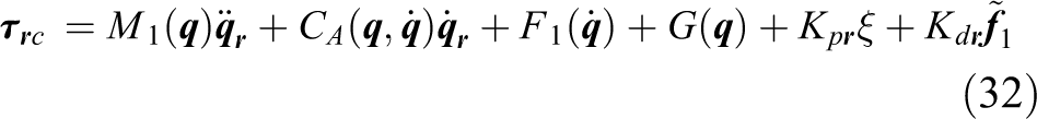
describes the model-based velocity controller with
Then, the signals
Remark 2
Note from equation (14) that the gain matrices
Remark 3
Before implementing the controller (equation (31)), it is worth noting that the complexity of its implementation may increase due to the presence of the terms
Experimental results
This section illustrates the performance of the previous chaotization procedure using a 2-DOF FJR manipulator. First, the experimental setup which consists of a Quanser 2-DOF FJR manipulator is described. Then, the chaotic reference field used in the experiments is presented. A methodology for computing the rotor and link velocities is also described. Finally, the analysis of the experimental results is provided.
Platform description
The experiments were carried out using Matlab-Simulink R2012b and the Quanser 2-DOF FJR manipulator depicted in Figure 4. Simulink models were built using a fixed step size of 1 ms and a solver ode3 Bogacki–Shampine. In the robotic platform, the joints exhibit visible harmonics during accelerations, while the links are rigid in comparison. The system has two DC motors, the Maxon (Maxon motor, Fall River, Massachusetts, USA) 273759 and 118752 for joints 1 and 2, respectively. Each motor drives harmonic gearboxes with null backlash in a two-bar serial linkage. Both links are rigid, the primary is coupled to the first drive by means of a flexible joint and it carries at its end the second harmonic drive, which is coupled to the second rigid link via another flexible joint. Both motors and flexible joints are instrumented with quadrature optical encoders of 4096 pulses per revolution. Note that the robot moves on the horizontal plane, which implies a null effect of the gravity on it.

Experimental platform of a 2-DOF FJR used in the experiments. DOF: degree of freedom; FJR: flexible joint robot.
The DC motors delivering torque at the joints are driven by servo amplifiers configured in current mode.
15,66
Hence, the torques applied at the joints are related with the motor current as

indicating that the delivered torque is proportional to the input servo amplifier voltage.
In the experimental platform, the motor torque constant matrix Km and servo amplifier gain matrix
respectively. Besides, the maximum torques delivered by motors 1 and 2 are
Regarding the dynamic model equations (1) and (2), the corresponding matrices for the experimental platform are 59,60


The definitions of parameters θi are given in Table 1 using the following notation mli
mass of link i, m
r1 mass of rotor i, L
1 length of link 1, li
distance to the center of gravity of link i, Ilzzi
principal inertia moment at z axis of link i, Irzzi
principal inertia moment at z axis of rotor i, ri
gear ratio of actuator i, k
s1 first FJR torsional stiffness, k
s2 second FJR torsional stiffness, f
1 viscous friction coefficient of link 1, f
2 viscous friction coefficient of link 2, f
3 viscous friction coefficient of joint 1, f
4 viscous friction coefficient of joint 2, f
c1 Coulomb friction coefficient of link 1, f
c2 Coulomb friction coefficient of link 2. f
c3 Coulomb friction coefficient of joint 1, f
c4 Coulomb friction coefficient of joint 2,
with
Parameters

DOF: degree of freedom; FJR: flexible joint robot.
Note that not all the system parameters θi are provided by the robot manufacturer.
60
Furthermore, during robot operation, some of these values may vary, which makes it necessary to include a parameter identification stage.
67
In this work, a dynamic filtering of the robot model, together with the application of a least squares parameter identification method, was used to estimate the values of the parameter vector
Chaotic reference field
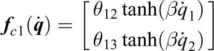
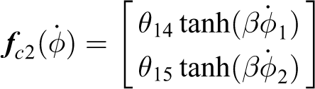
The velocity reference field

where

with
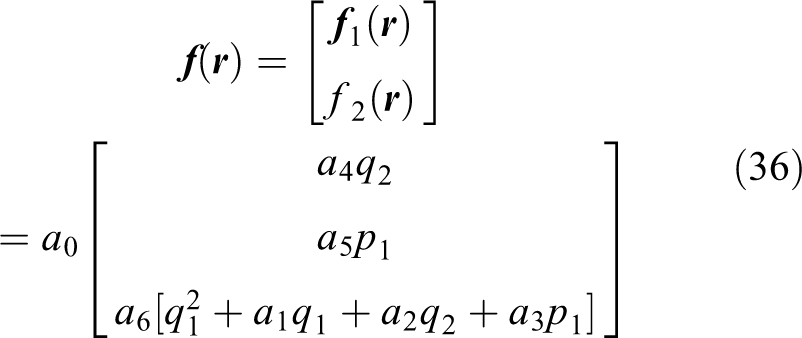
where
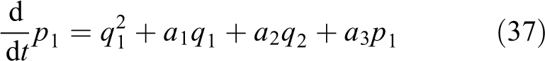
By using equation (34), the coordinate p1 can be obtained by solving the next differential equation
Velocity estimation
For a given real robotic system, it is usual to have only encoders for position measurement. Then, velocity values must be estimated using the encoder measurements. This is the case for our experimental robot. The velocity values

where
where k represents the time index, Ts is the sampling period, and

Finally, the velocity values were estimated by averaging the last

In this document, the velocity estimates were obtained using equation (38) with
Results and discussion
The experiments with the 2-DOF FJR were achieved by using

in the velocity reference field

In Figure 5, the time evolution of the torques applied at joints 1 and 2 is depicted. The control signals corresponding to each joint have high-frequency components. This behavior can be attributed to the fluctuation due to the pulse width modulation switching of the servo amplifier, quantized measurements of the angular position of the joints and the links, and the velocity estimation algorithm used to compute

Applied torques
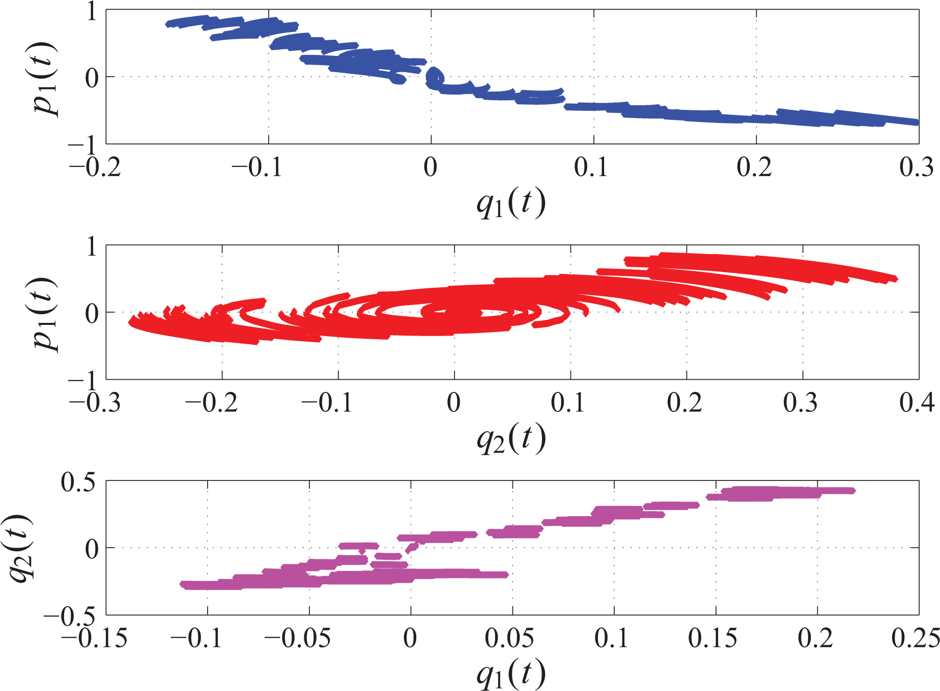
Using the measurements of the link positions

Chaotic attractor: view using the coordinates
From the experimental data corresponding to the time evolution of q(t) and
Poincaré maps generated for the planes:
The plot of the Poincaré maps is included as a numerical test, indicating that the robot motion is chaotic. Distinct set of points in the Poincaré map indicate the existence of chaos,
70,71
which is the case for the maps given in Figure 7. In addition, a way to determine if a system is chaotic consists of computing the Lyapunov exponents.
72
If the largest Lyapunov exponent is positive, then the associated system dynamics has a chaotic behavior. From the experimental data, the largest Lyapunov exponent was

Behavior of the components of the chaotization error vector
The experimental results indicate that the decoupling controller
Many future studies can be made in the chaotization field. For instance, for parameter identification of robot manipulators, it is essential to consider the spectral richness (SR) of the reference signal and the trajectories followed by the system. If the SR is high enough, it improves the accuracy of the parameter identification technique. This methodology may be approached by considering that the robot links follow a chaotic reference. Some interesting works dealing with parameter identification are covered by Boubaker and Iriarte 73 and Lassoued and Boubaker. 74 In addition, the improvements in the chaotization of FJR manipulators when using robust controllers can be verified. 73 Finally, other studies related to real-world applications of chaotic systems can be found in Boubaker and Jafary. 75
Conclusion
This article proposed a model-based velocity controller that allows achieving the chaotization of an n-DOF FJR manipulator. The methodology employed a chaotic reference field, namely a Genesio–Tesi system. A Lyapunov-based analysis demonstrated that the robotic system in closed loop with the proposed controller is asymptotically stable, guaranteeing the chaotization objective. The proposed controller was experimentally tested on a Quanser 2-DOF FJR manipulator. The experimental data were used to compute the Poincaré maps and the largest Lyapunov exponent. Because these maps presented distinct set of points and the largest Lyapunov exponent was positive, it was concluded that the robot links exhibited a chaotic motion, validating the effectiveness and robustness of the proposed controller. As a future work, robust control techniques will be used to induce a chaotic behavior to the FJR manipulator affected by matched and unmatched disturbances. Besides, we will make use of the chaotization procedure to verify improvements in parameter identification.
Footnotes
Acknowledgement
The authors gratefully acknowledge the financial support from CONACyT (Consejo Nacional de Ciencia y Tecnología).
Declaration of conflicting interests
The author(s) declared no potential conflicts of interest with respect to the research, authorship and/or publication of this article.
Funding
The author(s) disclosed receipt of the following financial support for the research, authorship and/or publication of this article: This work was financially supported by CONACyT (Consejo Nacional de Ciencia y Tecnología) under the Project Cátedras 1537 and grant 285279.