
Abstract
In this article, a robust model-free trajectory tracking control strategy is developed for a quadrotor in the presence of external disturbances. The proposed strategy has an outer-inner-loop control structure. The outer loop controls the position with adaptive proportional derivative-sliding mode control and generates the desired attitude angles for the inner loop corresponding to the given position, velocity, and heading references, while the robust integral of the signum of the error method is applied to the inner loop to guarantee fast convergence of attitude angles. Asymptotic tracking of the three-dimensional trajectories is proven by the Lyapunov stability theory. The effectiveness of the proposed controller is demonstrated with the simulation results by comparing with other model-free quadrotor trajectory tracking controllers.
Introduction
Due to vertical take-off/landing capability, flight flexibility, and hovering stability, quadrotor unmanned aerial vehicles (UAVs) have attracted increasing attention in the past decades and have been widely used in surveillance, search and rescue, and so on. 1,2
Trajectory tracking control of a quadrotor UAV is a challenging problem because of its nonlinear, strongly coupled, and underactuated dynamics. Moreover, the quadrotor system is susceptible to external disturbances such as wind, payload variations, and nonlinear frictions. 3,4
Significant efforts have been made, and various control methods have been developed for the trajectory tracking control of quadrotor UAVs. The control methods can be divided into linear control methods such as proportional derivative (PD), 5 –8 proportional integral derivative (PID), 9 linear quadratic regulation (LQR) 10 ; nonlinear control methods such as backstepping, 11,12 sliding mode control (SMC), 13 –16 model-free control (MFC), 17,18 adaptive control 19 –21 ; and intelligent control methods such as fuzzy control 22 –24 and learning-based control. 25,26 These controllers could achieve satisfactory performances for attitude or position tracking of quadrotor UAVs in some circumstances. Kendoul 4 designed a PD2 feedback controller for asymptotic attitude tracking of a quadrotor UAV. Pounds et al. 9 designed a PID controller for position and attitude stabilization of a quadrotor in the presence of load variation. Panomrattanarug et al. 10 designed an LQR-based attitude tracking controller in which the state variables are estimated using a full-order state observer. These linear controllers can stabilize the quadrotor’s position and attitude only around the operation point, whereas they cannot achieve the desired stability and tracking trajectories in a large operation range and have limited capability to alleviate the coupling among state variables.
Nonlinear control methods that can overcome the limitations of linear control approaches have been widely used in controlling quadrotors. Taking into account the input saturation, An et al. 11 designed a backstepping inverse optimal attitude controller that has the maximum convergence rate Derafa et al. 13 developed a second-order super twisting sliding mode controller (STSMC) for the attitude tracking control of a quadrotor to ensure robustness to modeling errors and wind perturbations. Their works focus on the attitude tracking problem while position trajectory tracking control is also very important in practical applications. In consideration of quadrotor actuator effectiveness loss, the trajectory tracking problem is treated using a nonlinear disturbance observer–based resilient backstepping controller. 12 An SMC is designed for autonomous flight control of a quadrotor to ensure the position and yaw angle reach to the desired values asymptotically. 14 Furthermore, a terminal SMC is designed to make the quadrotor reach to the state of equilibrium in finite time in the presence of unexpected disturbances. 15 Considering that the onboard altitude sensors (barometer, global positioning system, etc.) do not provide the altitude velocity information, a high-order sliding mode observer is designed to estimate the altitude velocity. Based on the estimations, an STSMC is designed to address the quadrotor altitude tracking problem. 16 However, the backstepping 11,12 and SMCs 13 –16 need good knowledge of the system dynamics, while the precise dynamic models of small quadrotor UAVs are very difficult to be obtained due to high coupling, uncertainties, and external disturbances. 27
Without the requirement of the dynamic model, the MFC is a preferred remedy in which only the system input and output are needed to estimate the local model. 17 Combining the MFC with the terminal SMC, a model-free terminal sliding mode controller (MFTSMC) is designed to control the attitude and the position of a quadrotor UAV. 18 The time-delay-estimation-based MFC ensures bounded tracking errors, while the terminal SMC eliminates the bounded error in a finite time. However, the estimated model of the MFC is valid only in a short period and needs to be updated in every iteration, and the control gains are not easy for tuning. Other model independent controllers have been designed. Adaptive control that is suitable to solve the parametric uncertainty problem has been utilized for trajectory tracking of a quadrotor in the presence of parametric uncertainties. 19 However, the classic adaptive control requires the linear parameterization of nonlinear dynamics, while nonparametric uncertainties usually lead to performance degradation. 28 Torres et al. 22 designed a fuzzy feedback controller in which a distributed compensator is designed to stabilize the quadrotor. In the study by Gautam and Ha, 23 the PID controller is combined with the fuzzy logic to address the quadrotor attitude and position control problem. The PID gains are tuned using a self-tuning fuzzy algorithm, whereas the fuzzy parameters are achieved based on an extended Kalman filter. In the study by Kayacan and Maslim, 24 a type-2 fuzzy neural network position controller is combined with the traditional PD attitude controller to solve the trajectory tracking problem of a quadrotor in the presence of disturbance and uncertainties. Lou and Guo 26 used reinforcement learning method for trajectory tracking of a quadrotor, while policy-searching algorithm is applied to adjust the model parameters and compensate for disturbances. Due to the strong learning abilities, the intelligent controllers have achieved good performance in quadrotor trajectory tracking. 22 –26 However, the intelligent controllers usually require high hardware conditions, which prevent their practical applications in low-cost quadrotors.
Recently, some simple MFC methods such as robust integral of the signum of the error (RISE) 29 and PD-SMC 30,31 have been proposed for trajectory tracking. The RISE controller can compensate for the disturbances and model uncertainties and ensure semiglobal asymptotic stability. It is applied for disturbance rejection in the inner loop of quadrotors. 32 In Shin et al.’s study, 33 neural network feedforward term is added to the RISE method to improve the attitude and altitude tracking performance of a rotorcraft. In the study by Yue et al., 34 the PD-SMC method that combines the advantages of PD control and SMC has been applied in the contour tracking control of robotic manipulators to improve tracking performance.
Motivated by the requirement for the simple controller which has strong robustness to external disturbances and can be implemented easily in practical applications, this article proposes a model-free hierarchical controller scheme for trajectory tracking of a quadrotor UAV. The proposed control scheme has an outer-inner-loop structure. First, a model-free adaptive proportional derivative-sliding mode control (APD-SMC) law is proposed for the outer loop to make the quadrotor UAV track the desired position trajectory in which adaptive laws is used to estimate the upper bounds of the unknown terms. The APD-SMC enables the quadrotor to achieve null steady-state error tracking capability with reasonable control gains so that the need for large control gains of PD-SMC to compensate for disturbances is avoided. Second, the boundary layer method is used to eliminate chattering of the APD-SMC. A tracking differentiator is utilized to compute the desired attitude angular velocity which is needed for the inner loop controller to overcome the infinity problem caused by taking the derivative of the desired attitude angles. Third, to meet the requirement for fast response of attitude tracking control, the RISE method is employed in the inner loop for disturbance rejection and ensures locally exponentially stability of the inner loop. Finally, the asymptotic convergence of 3-D trajectory tracking of the quadrotor UAV is proved by using the Lyapunov stability theory.
This article is organized as follows. The dynamic model of a quadrotor UAV is given in the second section. The details of the hierarchical MFC design and stability analysis are presented in the third section. The comparison simulation experiments of the proposed controller with other MFCs are given in the fourth section. The final section concludes the article.
Dynamic model description
The schematic of a quadrotor UAV is shown in Figure 1. The quadrotor has four rotors mounted at two orthogonal directions. Rotors 1 and 3 rotate in the anticlockwise direction; rotors 2 and 4 rotate in the clockwise direction. The four thrusts (fi , i = 1, 2, 3, 4) are generated by the rotation of the four rotors. The thrust is proportional to the square of the rotor’s angular speed 35,36

where the thrust coefficient kT depends on the blade rotor characteristics.

Schematic of a quadrotor.
The control inputs u, τ1, τ2, and τ3 can be obtained through the thrusts

where u is the total thrust; τ1, τ2, and τ3 are roll, pitch, and yaw control torques respectively; d is the distance from mass center to each rotor; and kc is the force-to-moment scaling factor. The descriptions and values of the quadrotor UAV physical parameters are given in Table 1.
Description of the quadrotor UAV parameters. 37

UAV: unmanned aerial vehicle.
As shown in Figure 1,

where
Assuming that the quadrotor UAV is a rigid body and it is symmetric around the center of gravity, its dynamic model can be expressed with Newton–Euler formalism

where

and

where

Remark 1
The attitude angles ϕ and θ are bounded as
Assumption 1
The unknown time-varying disturbances
Assumption 2
The state variables
The desired position and desired attitude are


The objective of trajectory tracking control is to design the control input u and τ such that the tracking errors
Here, the position
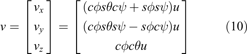
The total thrust u and 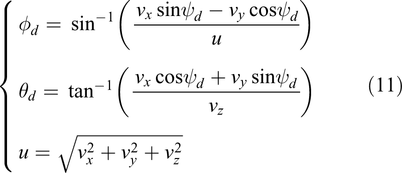
Remark 2
The reference trajectory
Controller design
Outer-loop position tracking controller based on APD-SMC
This section presents the hierarchical model-free tracking controller design. In order to achieve robust position tracking performance without the requirement for the quadrotor dynamic model, APD-SMC law is proposed in the outer loop to control the position of the quadrotor UAV. A continuous robust RISE feedback method is employed in the inner loop for attitude tracking control to compensate for the unknown disturbances. The block diagram of the overall control system is shown in Figure 2.

Block diagram of the overall control system.
The objective of this section is to design the virtual control input v to guarantee the globally asymptotically stability of the outer loop system and ensure the position tracking errors converge to zero. From equation (4), the outer loop subsystem can be described as

The position tracking error


Substituting equations (13) to (15) into equation (12), the dynamic model can be rewritten in the form of tracking errors as

where

where ‖⋅‖ represents the Euclidean norm and
From equation (16), it can be proved that the tracking errors could converge to zero if

where

where
Remark 3
The control law proposed in equation (18) is a combination of linear PD control and nonlinear SMC. The PD control which replaces the equivalent control part of the standard SMC is used to stabilize the nominal model, while the SMC and adaptive control are used to compensate for the unknown terms and improve robustness.
Remark 4
It can be seen that the APD-SMC law in equation (18) is only related to
Lemma 1
A matrix L is defined as follows

If
Proof
As Kp, mμ, and

If


As

The Schur complement 40 of Kp in L is

Thus,
Finally,
Theorem 1
Considering the outer loop subsystem in equation (12) with the proposed APD-SMC law in equation (18) and the adaption law in equation (19), the controlled system is globally asymptotically stable and the tracking error

Remark 5
For most translational robotic systems, their dynamics can be described as
For the quadrotor outer loop system described in equation (12), it is reasonable to assume that the mass m, aerodynamic damping matrix
Proof
Substituting equation (18) into equation (16), the dynamic model can be rewritten as

A positive Lyapunov function is defined as follows

where

Substituting equation (19) into equation (29), one can get

If

and

If

where
Thus,

Therefore,

The Lyapunov function
Remark 6
The

Inner-loop attitude tracking controller based on RISE
The objective of this section is to design the proper control inputs

where
The attitude tracking error


where
The auxiliary functions


According to remark 2, N(t) is continuous differentiable.

where the error vector Γ is defined as
The RISE feedback control law is chosen as

where
Remark 7
The inner loop control input designed in equation (45) is only related to the filtered tracking error
Next, the locally exponentially stable of the inner loop system is proven while a lemma is stated first.
Lemma 2
An auxiliary function

If the control gain matrix

then,
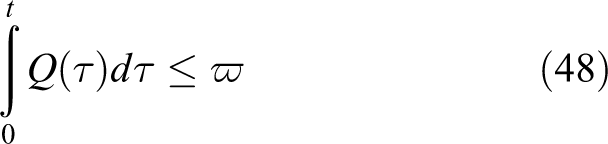
where ϖ is a positive constant defined as

and
Proof
Applying equation (40), equation (46) can be rewritten as

Then, one of its upper bound is obtained as follows

If βi (

Therefore,

Theorem 2
Given the attitude control system in equation (37) and provided that the control gains βi (
Proof
Define a Lyapunov function as follows

where

It can be seen that equation (46) in lemma 2 ensures that
The time differentiation of

Substituting equations (41) to (43) and equation (45) into equation (37), the closed-loop subsystem of

Substituting equations (38) to (40) and equation (57) into equation (56)

Equation (46) in lemma 2 ensures the term

where the positive constants δ and ϑ are defined as
Thus,

where ℓ is a positive constant. Based on the Lyapunov method, the inner loop is locally exponentially stable and the attitude tracking error
Remark 8
The attitude control law in equation (45) requires not only the desired attitude angle ηd but also the desired angular velocity
The tracking differentiator is designed as follows

where
Let


Remark 9
It can be seen in equations (62) and (63) that,
Simulation results
Extensive simulation experiments have been done to demonstrate the effectiveness and robustness of the proposed control strategy for trajectory tracking of a quadrotor. The quadrotor model parameters and their values are listed in Table 1, which are chosen from the test used in the study of Khatoon et al.. 37 The simulation experiments compare the tracking performances of the proposed control strategy with those achieved by the PD+PD, PID+PID, MFTSMC, 18 adaptive, 19 and PD-SMC+RISE controllers. The control gains of these controllers which are adjusted with trial and error are listed in Table 2. All the simulation experiments are conducted in Matlab R2016a on a PC with Intel (R) Core I7-4790 @ 3.6 GHz CPU, 8 GB RAM, and 1000 GB solid state disk drive.
Control gains.

PD: proportional derivative; MFTSMC: model-free terminal sliding mode controller; SMC: sliding mode control; RISE: robust integral of the signum of the error; APD: adaptive proportional derivative.
Remark 10
PD+PD, PID+PID, and PD-SMC+RISE mean that the outer loop controllers of these control scheme are PD controller, PID controller, and PD-SMC, respectively, and the inner loop controllers are PD controller, PID controller, and RISE controller, respectively.
Case 1: Chattering eliminating
In this section, the trajectory tracking performances of the APD-SMC using
The desired trajectory is given as

The initial position and attitude of the quadrotor are set as

The trajectory tracking results are shown in Figure 3. Position tracking errors are depicted in Figure 4. The virtual control inputs vi (

Trajectories in 3-D space. 3-D: three-dimensional.
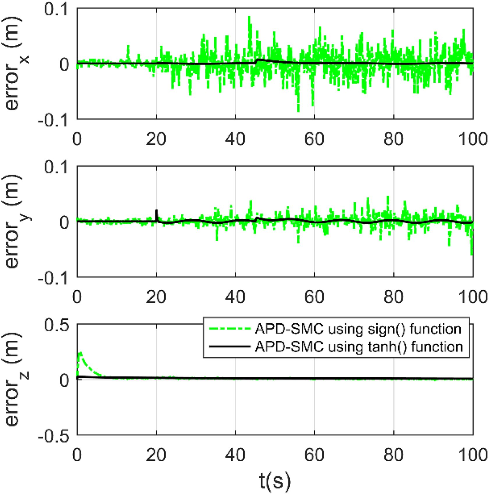
Position tracking error.
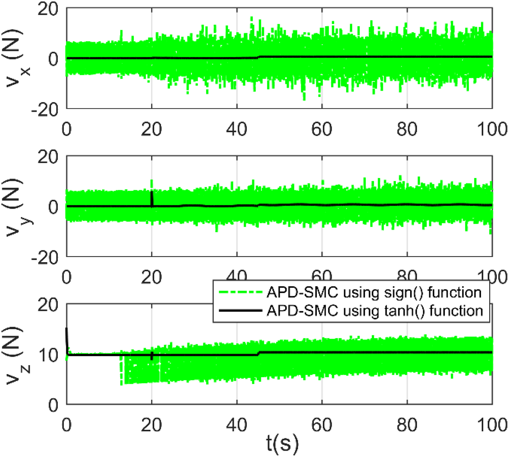
Virtual control inputs.
Case 2: Comparison of trajectory tracking performances of different controllers
In this case, trajectory tracking performances of PD+PD controller, adaptive controller 19 and APD-SMC+RISE controller are given. The reference trajectory, quadrotor initial states, and external disturbances are the same with those in case 1.
The tracking performance of the proposed control strategy is compared with those achieved with PD+PD controller and adaptive controller. The reference trajectory and the tracking trajectories are shown in Figure 6. The position tracking errors along three axes in the earth-frame coordinates are shown in Figures 7 to 9.

Reference trajectory and the tracking trajectories of different controllers in 3-D space. 3-D: three-dimensional.
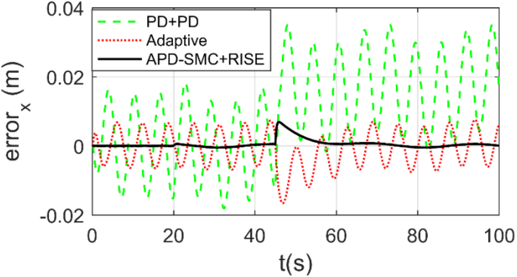
Position tracking error in x-axis.

Position tracking error in y-axis.
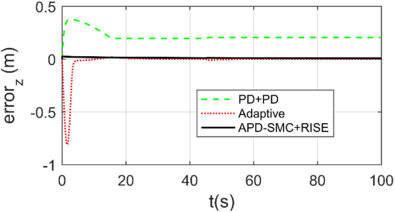
Position tracking error in z-axis.
As shown in Figures 6 to 9, it can be seen that the quadrotor cannot obtain the null steady-state error with the PD+PD controller. When the time-invariant persistent disturbances
As is shown in Figure 9, significant error occurs at
Compared with PD+PD controller and adaptive controller, the proposed APD-SMC+RISE controller could quickly response to the disturbance and drive the quadrotor UAV to the desired positions without steady-state error. In addition, as is shown in Figure 8, the aggressive upward desired linear speed command
The attitude controlling errors are shown in Figures 10 to 12. It can be seen that under the APD-SMC+RISE controller, the attitude trajectories are tracked with the highest accuracy. We can also see in Figures 10 and 11, because of the state changing, significant errors occur at
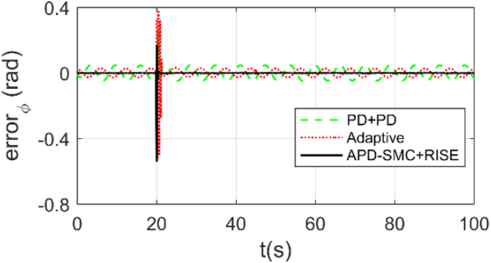
Roll angle tracking error.

Pitch angle tracking error.

Yaw angle tracking error.

Control inputs.
Case 3: Trajectory tracking performances in case of wind gust
The trajectory tracking results of MFTSMC
18
and APD-SMC+RISE controller in the presence of wind gust are given. The desired trajectory is the same as that in case 1. The wind gust

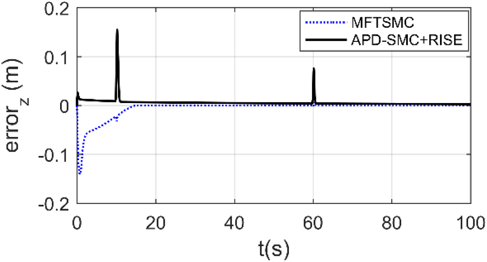
Figure 14 shows the position tracking results of MFTSMC and APD-SMC+RISE in the presence of wind gust. Figures 15 to 17 present the position tracking errors.

Tracking trajectories in case of wind gust in 3D space. 3-D: three-dimensional.

Position tracking error in x-axis.

Position tracking error in y-axis.
Position tracking error in z-axis.
It can be seen in Figures 15 to 17 that the two controllers could achieve satisfactory tracking performances. However, as is shown in Figure 17, it takes a long time for the MFTSMC to estimate the initial model of the altitude subsystem. In addition, when the wind gust is imposed on the quadrotor at

Roll angle tracking error.

Pitch angle tracking error.
In contrast, as is shown in Figures 15 to 17, because there is no need to estimate the quadrotor dynamic model, the convergence time under the APD-SMC+RISE controller is much shorter than that of the MFTSMC. When the wind gust is introduced, the proposed controller could drive the quadrotor to the desired trajectory in short time. Attitude tracking errors are shown in Figures 18 to 20. It can be seen that the desired attitude trajectories are well tracked without significant errors under the APD-SMC+RISE controller.
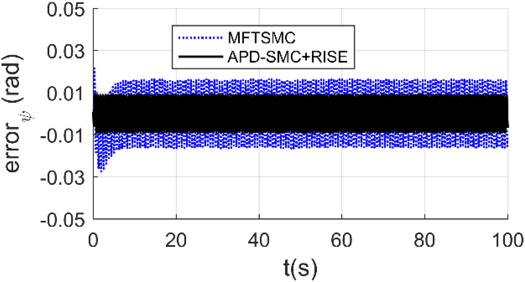
Yaw angle tracking error.
Case 4: Space circle trajectory tracking in case of parametric variation
This section gives the tracking results of the PID+PID controller, PD-SMC+RISE controller, and APD-SMC+RISE controller in the presence of parametric variation. The desired trajectory is given as

The initial position and attitude of the quadrotor are set as

where


Space circle trajectory tracking results are shown in Figure 21. Position tracking errors are shown in Figures 22 to 24. As shown in Figures 21 to 24, the PID+PID controller achieves good tracking performance. However, the overshoot and the settling time of the PID controller are much larger and longer than those of the APD-SMC+RISE controller. It also can be seen that, before ds
is introduced, the tracking performance of PD-SMC+RISE controller is almost as good as that of the APD-SMC+RISE. However, when ds
is introduced at

Space circle tracking performance of different controllers.

Position tracking error in x-axis.
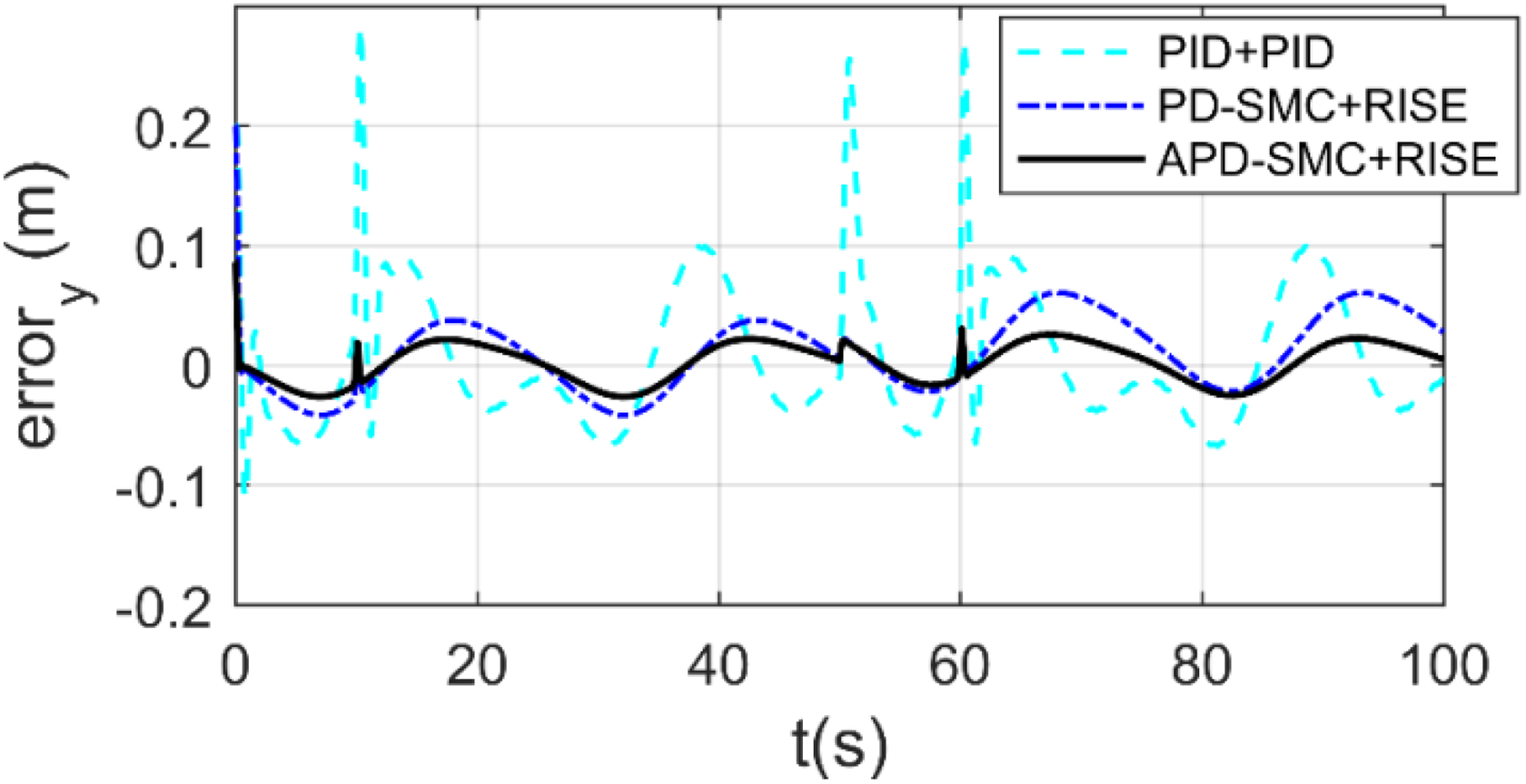
Position tracking error in y-axis.

Position tracking error in z-axis.
Compared with the PID+PID and PD-SMC+RISE controllers, the APD-SMC+RISE controller has the best tracking performance. As shown in Figures 22 to 24, the overshoot and settling time under the APD-SMC+RISE controller are smaller and shorter than those under the PID+PID controller. Above all, by introducing the adaptive estimations, the APD-SMC+RISE controller achieves adaptive tracking capability and the disturbances have been well compensated with reasonable control gains.
Summing up, the above simulation results have validated that the proposed control strategy could not only track complex trajectories with high accuracy but also have strong robustness against various disturbances.
Conclusions
This article studies the trajectory tracking of a nonlinear underactuated quadrotor UAV and proposes a robust model-free hierarchical controller. On one hand, a robust APD-SMC law is designed for the outer loop to drive the quadrotor track the desired position trajectory with null steady-state errors and the requirement for accurate dynamic model is also avoided. On the other hand, RISE feedback control method is employed in the inner loop for attitude tracking control and disturbance rejection. The proposed controller not only has simple structure but also has strong robustness to various external disturbances. Its effectiveness has been validated by extensive simulation experiments. Further work will focus on validating the proposed control strategy in practical applications.
Footnotes
Declaration of conflicting interests
The author(s) declared no potential conflicts of interest with respect to the research, authorship, and/or publication of this article.
Funding
The author(s) received no financial support for the research, authorship, and/or publication of this article.