
Abstract
A service robot for Cultural Heritage frames is proposed as a novel robotic platform with a modular design for both ground locomotion and flight capability. The peculiarities of the system are discussed by performance evaluation via simulation. A prototype has been built and tested both to prove the feasibility of the proposed design and to characterize its operation performance.
Introduction
The International Organization for Standardization defines a “service robot” as a “robot that performs useful tasks for humans or equipment excluding industrial automation applications.” 1 Service robots can have many shapes and structures and they can serve in many application areas as outlined in the reference handbook by the International Federation of Robotics. 2 Activity in Cultural Heritage frames can be aimed at improving the efficiency of the actions and decreasing the cost of interventions. 3 Exploration and maintenance of Cultural Heritage sites can be application areas with great potential for service robotics.
Several robotic solutions and designs can satisfy the requirements for applications in Cultural Heritage frames. Suitable mobile robots and drone systems can be found in a wide range of solutions from other application fields both at market sales and lab prototypes. 4 –10 Rovers, either with wheels or crawlers, are suited to inspection tasks in risky environments or for surveillance purposes. 4 –7 On the other hand, drones have been developed in the last decade and they present a variety of solutions for aerial monitoring of areas. Today, market products are available with features that range from toy applications to sophisticated solutions. 8 –10 Attempts of specific systems for Cultural Heritage frames are reported by Ippolito and Cigola. 11
This article presents a successful design that integrates a legged mobile robot and a drone module in order to get a robotic platform that has mobility capability both in terrain and aerial areas and has the possibility to be equipped with sensors and instrumentation for applications in Cultural Heritage frames. This solution has been developed within the HeritageBot project in Cassino. 12 Significant attention is addressed to the design process based on the peculiar design requirements for Cultural Heritage sites. Numerical simulations are carried out to evaluate and predict the robot performance, as well as to adjust the mechanical design and operation. Then, experimental tests are carried out in order to validate the engineering feasibility and effectiveness of the proposed design solution.
Requirements
Requirements for a robotic HeritageBot platform for servicing in Cultural Heritage frames can be identified in structure characteristics and operation peculiarities
13
such as: capability of data acquisition with autonomous or tele-supervised action, with onboard data storage capacity, mainly in areas of difficult access to human operators; capability of interventions for checking or collecting samples from the environment by using a small arm or other devices that can be installed on the platform on demand; capability of investigations with different instruments (e.g. colorphotogram analysis, radiography, laser beams, etc.) that can be installed for specific purposes on demand, such as for identification of the status of environments and objects; mobility capacity in walking and small flight with modularity of the robotic platform design; user-oriented cost of the platform design at affordable budget by operators in Cultural Heritage programs; user-oriented operation of the platform at skill reach of the potential users by using a joystick or teach pendant and by user affordable programming; modularity of the robot design permitting adaptation of the structure and its operation to the levels of task planning in Cultural Heritage programs.
The above requirements can be summarized as in the conceptual scheme in Figure 1 in which the main requirements are of inspiration for a general solution for the proposed HeritageBot platform. In particular, locomotion on the ground is achieved by means of a quadruped legged module, chosen for being the lightest system to perform static balanced walking, 14 while the small flight is performed by a drone module with four helices. The robot is driven by the user through a remote controller.
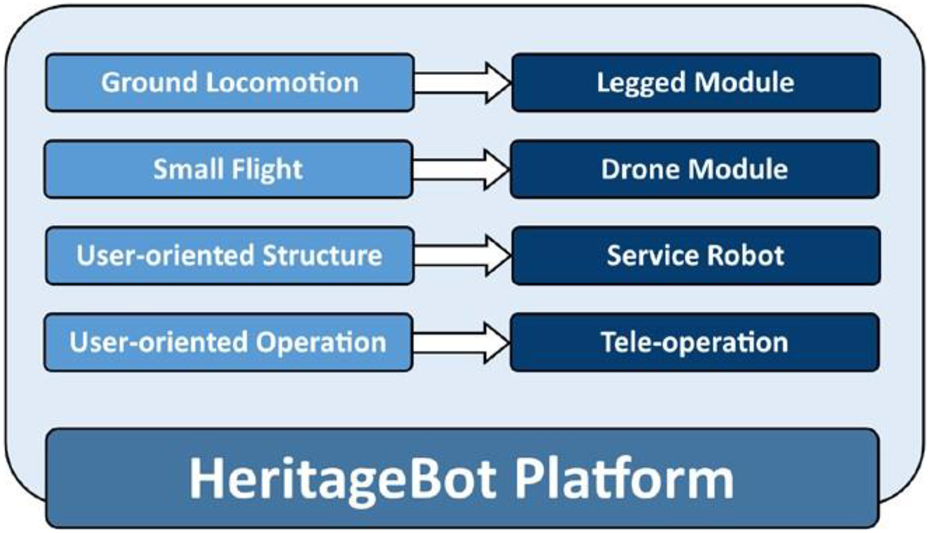
Requirements for the HeritageBot platform versus solutions for conceptual design.
Platform design
Three main modules have been designed to build a modular platform as in the conceptual design schemes in Figure 2. 15

Conceptual design of the HeritageBot platform: (a) overall design; (b) the modules structures as in the study by Ceccarelli et al. 15
The first module hosts the control system, including batteries and communication hardware, as well as specific sensors and instrumentation that are needed by the users for specific tasks. The second module is a quadcopter-like system that allows a small flight operation to help avoid the obstacles and increase the payload/stability capacity of HeritageBot. Additional propellers could be added in case of a need. Nevertheless, a solution with more propellers has been considered unnecessary in Cultural Heritage frameworks for several reasons such as the recent regulation constraints for flying devices as well as the limits given by the battery size and autonomy. The third module is a quadruped walking robot that is based on a tripod parallel architecture, which has a patent pending by the team at Laboratory of Robotics and Mechatronics. 16 The key features of this architecture are the very high payload when compared to its own weight and a wide step range. A computer-aided design (CAD) model of the entire robot is shown in Figure 3. The expected characteristics of the main design are summarized in Table 1. Beside the technical characteristics, the design requirements are characterized by the implementation in Cultural Heritage frames that require mainly a limited cost both for the system and its operation so that the service robot should be developed also using commercial components.

A CAD model of the proposed mechanical design in Figure 2. CAD: computer-aided design.

The HeritageBot design is developed to operate it in narrow spaces, in the presence of obstacles comparable to the HeritageBot platform size, while avoiding high pressures or damages on the operation surface.
Performance evaluation via simulation
Performance evaluation has been carried out via simulation both to define the mechanical design and to characterize the operation feasibility. Results are reported from simulation computations for dynamic modeling and stress analysis.
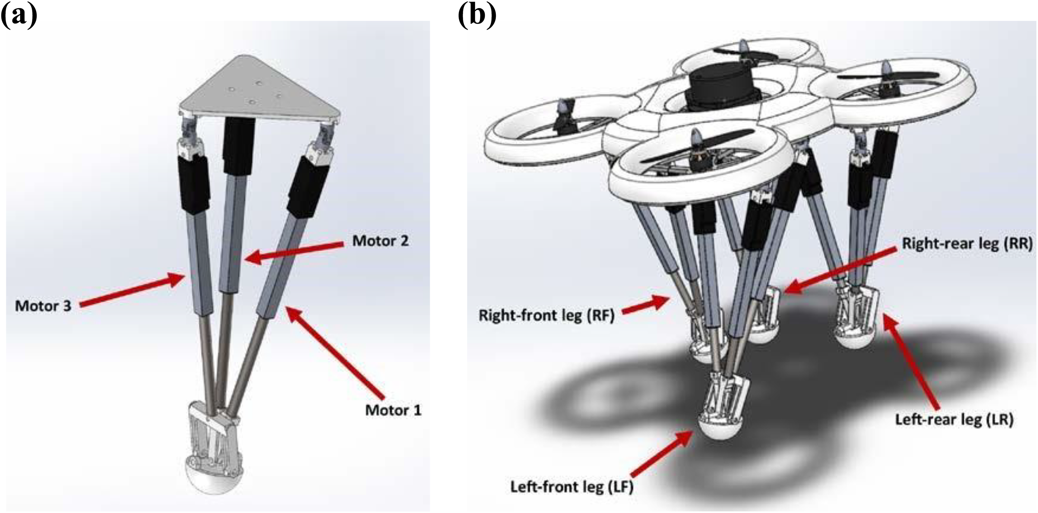
The design data in Table 1 and the CAD model in Figure 3 for the simulation of the walking operation are based on the mechanism design by Russo and Ceccarelli 17 and its optimized solution by Russo et al. 18 as shown in Figure 4, where the 12 linear motors actuate the quadruped module. Snapshots taken during the walking simulation are shown in Figure 5, while the resulting actuator forces are reported in Figures 6 to 9. The dynamic simulation has been performed for the case of a static walking operation that is characterized by a constant velocity of the center of mass of the robot. The simulated walking velocity is equal to 50 mm s−1. In each moment of the gait, three out of four legs are always in contact with the ground in order to achieve a static balance condition. The step length for the simulated operation is equal to 150 mm, while the step height is equal to 30 mm. The maximum force of the motors is lower than 30 N, which is well below the maximum motor force that a suitable commercial linear motor can provide. Therefore, the simulation shows that the quadruped module can be actuated with commercial servomotors for a stable walking of the HeritageBot platform at a constant speed. The gait is obtained by a proper motion of the legs with a sequence as shown in Figures 6 to 9. In particular, Figures 6 to 9 show the characteristic time history of the actuation force in each leg linear motor having two motors acting in the same way when the direction of the motion is orthogonal to their assembly configuration.

Snapshots from the dynamic simulation of the walking operation mode of the HeritageBot platform (the red row indicates walking direction).

Results of dynamic simulation of the walking operation mode in terms of actuation force versus time for the three motors of the left-front leg (motor 1 and motor 2 overlap).
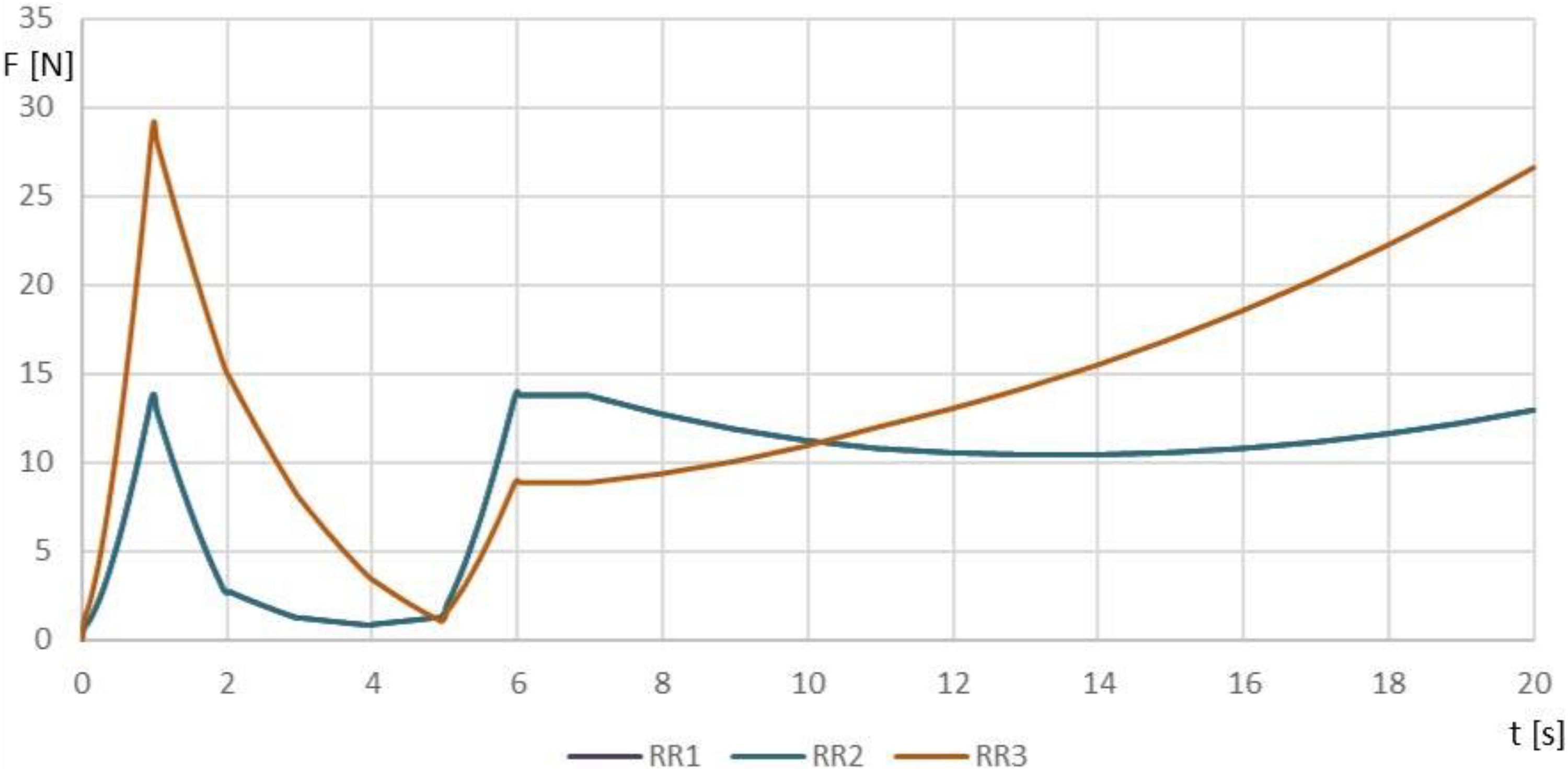
Results of dynamic simulation of the walking operation mode in terms of actuation force versus time for the three motors of the rear-right leg (motor 1 and motor 2 overlap).
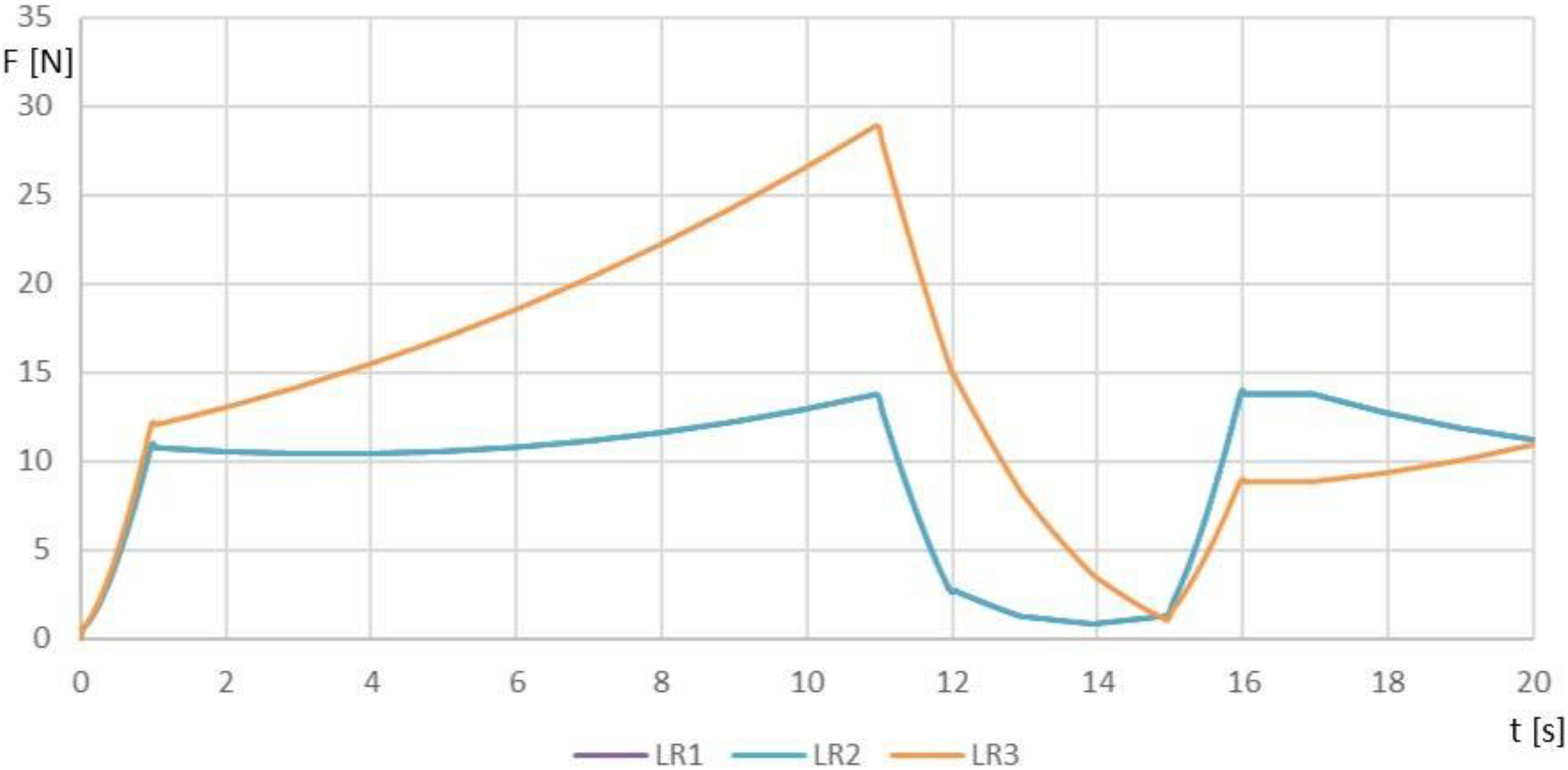
Results of dynamic simulation of the walking operation mode in terms of actuation force versus time for three motors of the left-rear leg (motor 1 and motor 2 overlap).

Results of dynamic simulation of the walking operation mode in terms of actuation force versus time for three motors of the right-front leg (motor 1 and motor 2 overlap).
A stress analysis of the platform structure has been performed using a finite element method (FEM) in order to evaluate the stiffness of the structure under external loads, including instrumentation weight. The CAD design of the platform structure for the analysis is shown in Figure 10(a) combining the plates of the three muddles in one platform. Load conditions are given by forces and moments that have been computed through dynamic simulation of walking operation considering the weight of the platform and instrumentation. The platform structure has been assumed as made of polylactic acid plastic, thanks to a three-dimensional (3-D) printing manufacturing, 19 whose mechanical properties can be summarized with tensile strength of 3.00·107 Nm−2, elastic modulus of 2.00·109 Nm−2, Poisson’s ratio of 0.40, mass density of 1020.00 kg·m−3, and shear modulus of 3.19·108 Nm−2.

Design of the prototype platform structure: (a) CAD model; (b) results from FEM analysis. CAD: computer-aided design; FEM: finite element method.
The meshing of the 3-D model has been defined with a solid mesh with four Jacobian points with elements that are characterized by a minimum size of 5.52 mm and a maximum size of 27.60 mm. Von Mises stress function has been used as stress analysis criterion in order to have a measure that considers the three stress components of a general 3-D state of stress. The results of the FEM analysis are reported in Figure 10(b) with maximum stress of 2.58·106 Nm−2, maximum displacement of 5.19·10−3 mm, maximum strain of 1.11·10−3 mm, and maximum force of 551.20 N. From Figure 10(b), it is possible to note that the maximum stress values in red are due to the leg action since they can be observed in the regions where the legs are connected. The other maximum stress values occur on the edge of the platform arms, where actuators of the propeller module are connected. Nevertheless, the computed stress never exceeds the material yield strength.
A computational fluid dynamic (CFD) analysis has been then performed in order to validate the drone design (Figure 11). The weight of the drone module has been assumed to be equal to 850 g, with an additional load of 2000 g due to the leg module and onboard sensors. The performance of the drone module has been evaluated using SolidWorks 2017 CFD toolbox. The efficiency of the module is equal to 0.629 in hovering mode, while the maximum efficiency during flight operation is 0.719. The power consumption in hovering mode is computed for 122.9 W and the maximum power consumption is estimated to be 368.5 W. The maximum tilt angle of the platform is equal to 55°, with a maximum flight speed of 31 km h−1 and an estimated ascent rate equal to 5.3 m s−1.

Computed results of a CFD analysis for the operation of the drone module in the designed platform. CFD: computational fluid dynamic.
The numerical results of the simulations as partially reported in the article show feasible performance of the proposed platform structure with significant payload capability and stiff response because of a robust mechanical design made with compact size and proper servo-controlled actuations.
The low-cost prototype HeritageBot III
The HeritageBot III (HBIII) prototype has been manufactured through 3-D printing technology using common commercial components. The final prototype is shown in Figure 12(a) during a walking operation and in Figure 12(b) while flying.

The HBIII prototype of HeritageBot platform during test for: (a) outdoor walking operation; (b) small flight operation. HBIII: HeritageBot III.
The quadruped locomotor module uses 12 Actuonix Linear Actuators L16-P 20 to actuate the leg structure as controlled by a Arduino control board for each motor shield. A central control board communicates with the control of each leg in order to synchronize and coordinate the entire motion through I2C protocol to perform suitable gait for walking motion. The designed control system permits to change the leg module even by changing the leg structure without affecting the prototype walking behavior since the actuator control is performed at the leg module level.
Four brushless motors (type S5008—300 kV) are used to drive the helices of 18 × 5.5-inch dimensions, made of carbon fiber, through a specific control system for the drone module. The control system has been properly designed and tested to ensure proper propeller motions through 40A Electronic Speed Control (ESC) with a maximum thrust of 2985 g by a supply of 22.2 V.
An additional control system is designed to manage the onboard sensors and to communicate with the remote controller through a remote user interface that is able to send telemetry data of the center of mass of the structure, such as position, angular displacement, linear and angular accelerations, altitude, and temperature. Figure 13(a) shows an upper view of the used hardware for central control unit and flight control unit, while Figure 13(b) shows the leg module control unit. All the mechanical parts and shells of the structure have been manufactured through 3-D printing with PLA plastic and flexible rubber-like filament. The full system is supplied by a 22.2 V battery and a voltage regulator allows the battery to supply the control board and sensors through a voltage step-down.
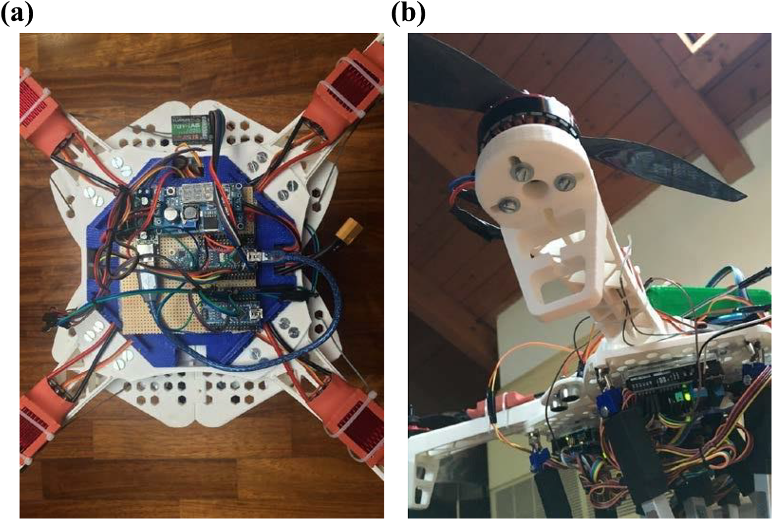
Component assembly of control boards in the HBIII prototype for: (a) drone module; (b) locomotor module. HBIII: HeritageBot III.
The overall mechanical design of the built prototype HBIII is characterized by fulfilling the expected design goals in Table 1 with the characteristics as listed in Table 2.
Main design characteristics of the prototype HBIII for the HeritageBot platform in Figures 12 and 13.
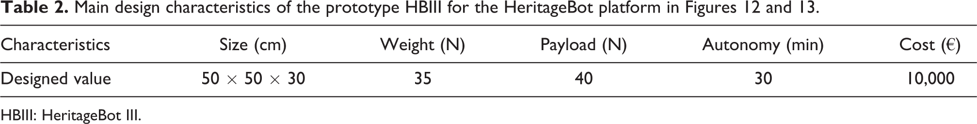
HBIII: HeritageBot III.
The built demonstrative prototype HBIII is characterized to have been assembled with commercial components and manufactured parts for a low-cost solution at a total cost of about €10,000 as planned for the HeritageBot research project.
Experimental tests
Experimental tests have been carried out both to validate the proposed design and to characterize the operation performance both in walking and flight modes.
The controller of the prototype activates the walking mode and the small flight mode with altitude hold. When altitude hold mode is selected, the throttle is automatically controlled to maintain the current altitude during small flight. The user directly controls the roll and pitch lean angles and the heading with the drone module. Keeping a constant altitude is not a trivial task, especially if the prototype is supposed to stay very precisely at a given altitude of few meters above the ground. One of the reasons is the difficulty of reading the precise altitude with the onboard low-cost instrumentation. In fact, the barometer can drift when atmospheric pressure changes and can produce a lot of noise. In order to compensate this error, the barometer is planned to work in combination with the ultrasonic sensor.
A test of the drone module has been performed outdoor to evaluate the behavior of the prototype against unforeseeable forces, as shown in Figure 14. Figure 14(a) shows the starting position where the propeller module alone is on the ground and powered on. After a calibration procedure, the actuators are powered on and the target altitude is set with the default acceleration to allow the prototype to fly. Figure 14(b) shows the prototype performing a stable flight at a prescribed altitude of less than 8 m.
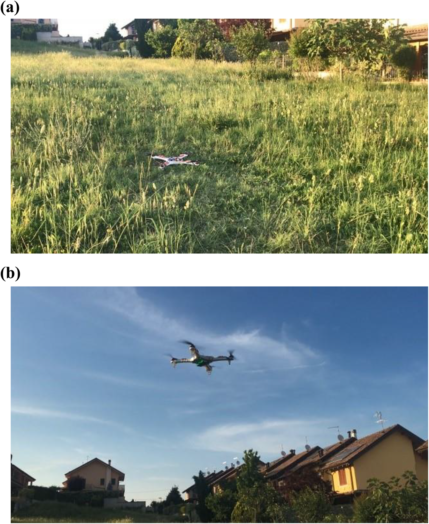
An outdoor test of the flight module of HBIII: (a) starting position; (b) stationary flight at a prescribed altitude of 8 m.
The prescribed altitude is ensured through a properly designed proportional–integral–derivative (PID) control to maintain the undesired angular displacement of the prototype as near to zero as possible. The altitude hold proportional control is used to convert the altitude error, which is the difference between the desired altitude and measured altitude, to a desired climb or descent rate. The desired altitude is set with a trimmer that is located on the remote control. A higher rate makes a more aggressive attempt to maintain its altitude but, if set too high, it leads to a convulsive throttle response. The integral and derivative controls help the stabilization of the flight behavior. The PID control gives a throttle capable of maintaining the desired output that varies from 1000 to 2000 µs. This value represents a pulse-width modulation (PWM) signal. A PWM signal is a square wave signal consisting of high and low voltage signals, given as 5 V and 0 V, for certain durations. This output signal is sent to the ESC of the motor, which is an electronic circuit with the purpose to determine the electric motor speed, its direction, and even its action as a dynamic brake. The ESC sets the speed of the motor depending on the ratio between high and low signals. Calibration involves a programming of the ESC to understand the PWM waves corresponding to the stop and maximum speeds of a motor. The default signal range for most servomotors and ESCs is a high signal width between 1000 and 2000 µs over a repetition period of 20 ms once settling a 50 Hz PWM signal. For the flight mode, the range has to be as wide as possible to allow for proper incremental control of the motor. Therefore, the ESCs have been calibrated to read a signal width from 1000 to 2000 µs with 1000 being the stop speed and 2000 being the maximum speed. The throttle rate converts the desired climb or descent rate into a desired acceleration up or down.
Figure 15(a) shows the numerical results of an altitude hold PID reaction test in which the prototype is maintained in a stable position and the desired altitude is increased step by step from 100 mm to 600 mm using the remote command trimmer. The PID reacts linearly, giving an output from 1100 µs to 1800 µs showing a satisfactory behavior until reaching the maximum speed. The control increases the speed in order to reach the desired altitude. Figure 15(b) shows a test in which the desired altitude is constant at 100 mm and the prototype is able to move. The controller recognizes that the desired altitude is not reached and sends proper PWM signals to the ESCs up to 1250 µs, so that the motors of the prototype start and increase their speeds to generate the needed thrust to fly. When they reach a higher altitude than the desired one, they decrease the throttle rate to descend and maintain the desired one.

Numerical results of a PID reaction test of the drone module for (a) an altitude increase and (b) a stationary flight at 100 mm. PID: proportional–integral–derivative.
Figure 16 shows the acquired linear acceleration along the XYZ axis of the prototype during a small flight test of the drone module. The plot shows that there is a sudden acceleration due to the prototype lifting that is followed by some bending while flying. Finally, at 8 s, the procedure for landing starts. Acceleration az has an offset of 1 g since it is the axis along which the acceleration of gravity acts.
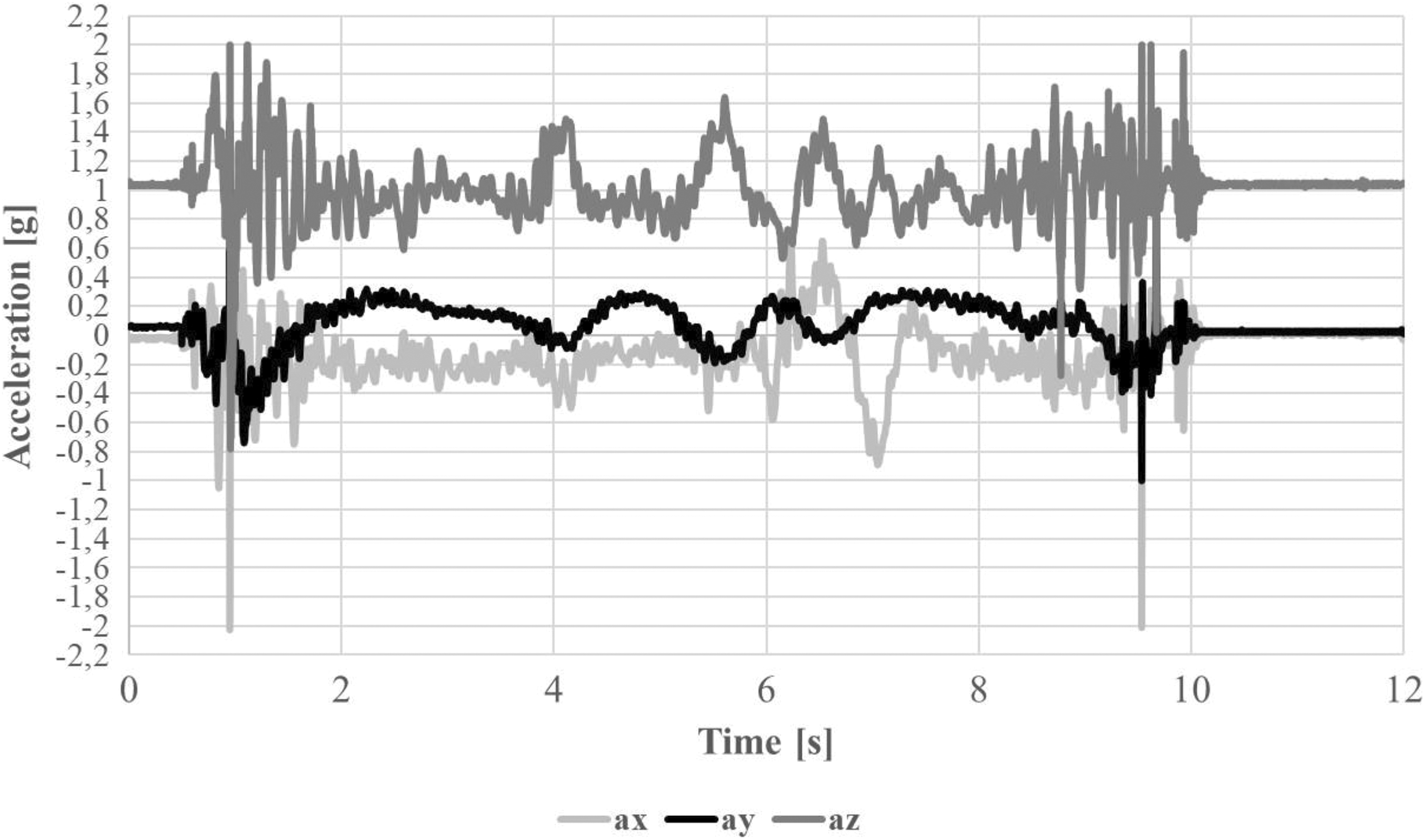
Acquired linear acceleration during a small flight test of the drone module.
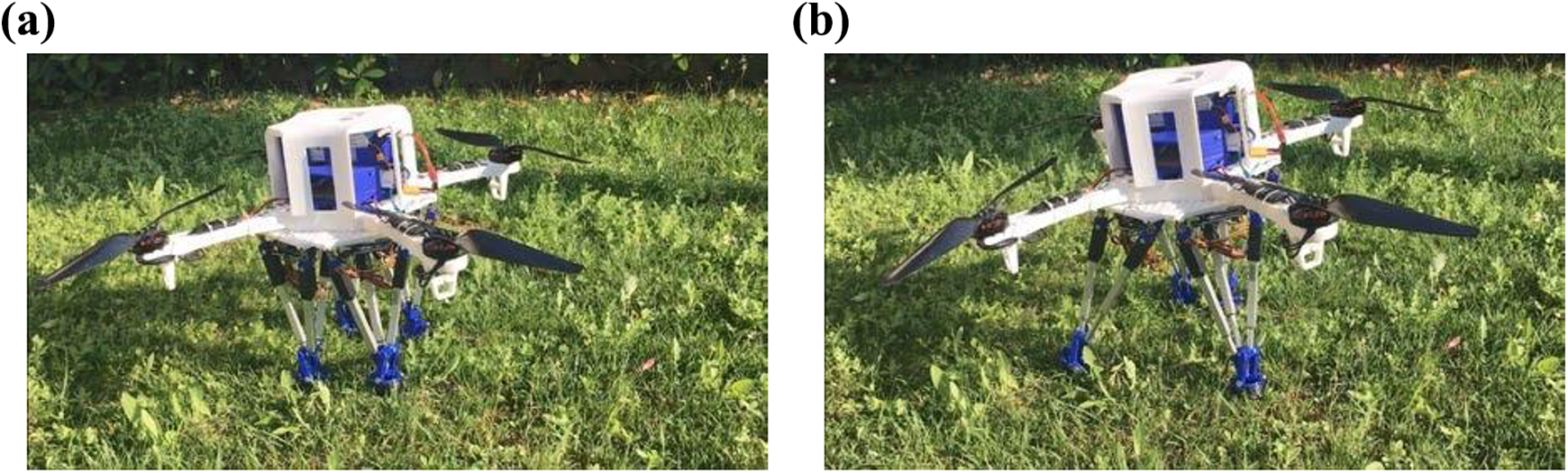
The walking mode of HeritageBot platform has been tested both indoor and outdoor to verify the behavior of the prototype HBIII while walking on different types of grounds. Figure 17 shows an indoor walking test of the HBIII robotic platform, while Figure 18 shows an outdoor test for the same operation. The gait cycle for both tests is set to 35 s.

An indoor walking test of the HBIII prototype at LARM in Cassino: (a) starting home position, (b) first step moving front legs. HBIII: HeritageBot III; LARM: Laboratory of Robotics and Mechatronics.
An outdoor walking test of the HBIII prototype: (a) starting home position, (b) first step moving front legs. HBIII: HeritageBot III.
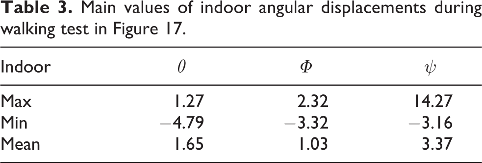
In order to characterize the walking behavior of the HeritageBot platform among different types of terrain and to be able to compare them, an inertial measurement unit sensor has been installed in the center of the drone module platform to measure angular displacements and linear accelerations, namely around and along the X, Y, and Z axes. The reference axes are placed in the center of mass of the prototype. The angle θ is the angular displacement along the X axis, Φ is the angular displacement along the Y axis, and ψ is the angular displacement along the Z axis. The angular displacements show a bending along the X and Y axes while walking and turning with a clockwise rotation. When the walking operation finishes, the platform recovers the starting angular position. Table 3 lists the maximum, minimum, and mean value of θ, Φ, and ψ during indoor walking operation, while Table 4 lists the maximum, minimum, and mean value of θ, Φ , and ψ during outdoor walking operation. One can note that the motion behavior is quite similar in the two tests with similar values in angular displacements showing a satisfactorily smooth motion.
Main values of indoor angular displacements during walking test in Figure 17.
Main values of outdoor angular displacements during walking test in Figure 18.

This is also observable in Figure 19 where the linear acceleration components are reported for the case of the indoor test. The initial peaks are related to the starting up of the motion that during the walking is performed with satisfactory low vibrations. In fact, Fig.19 shows small acceleration values with less than 0.15 g magnitude and a quite stationary response. In addition, by comparing the results of the indoor and outdoor tests, it is possible to observe that rough terrain does not affect significantly the motion characteristics of the prototype operation.
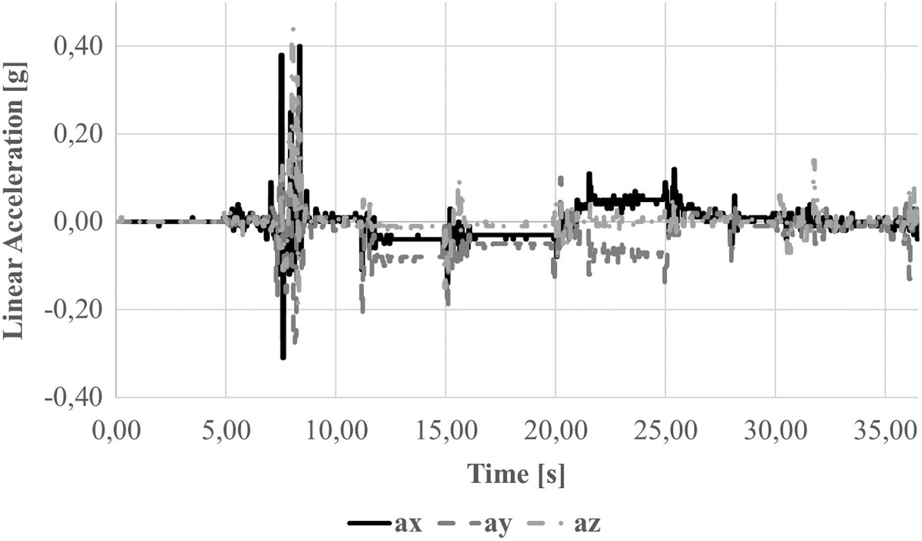
Acquired linear acceleration during an indoor test of the walking module in Figure 17.
Figure 20 shows computed results for the power consumption of the HBIII design during a test combining walking and small flight. The four small peaks are related to four steps during which the leg moves by the linear actuators consuming less than 400 W at each step, while the large peak corresponds to the small flight during which the four propellers consume about 2000 W. This shows that the walking mode is more energy efficient while it confirms the feasibility and effectiveness of the small flight operation for specific obstacle avoidance tasks and/or for specific motions with limited durations and limited effects on the energy consumption and robot autonomy.

Computed power consumption during a test of walking and small flight of the HBIII design of the HeritageBot platform. HBIII: HeritageBot III.
The operation tests with HBIII prototype have given satisfactory results that validate the proposed design of the HeritageBot platform in terms of motion performance both in walking and flight modes.
Conclusions
The HeritageBot platform is presented as a service robot for Cultural Heritage. This article is focused on the characterization of the mechanical design of the robotic platform with its modularity and mobility both for ground locomotion and small flight. The performance of the robot is evaluated through numerical simulations, namely a multibody dynamics simulation to analyze the ground locomotion, a FEM stress/strain analysis of the drone platform, and a CFD simulation for the small flight mode. A prototype has been built in order to validate the numerical simulations and to characterize the feasibility of the proposed robotic platform design. Results of experimental tests are presented to check proper efficiency of the prototype both for ground locomotion and small flight.
Footnotes
Declaration of conflicting interests
The author(s) declared no potential conflicts of interest with respect to the research, authorship, and/or publication of this article.
Funding
The author(s) disclosed receipt of the following financial support for the research, authorship, and/or publication of this article: The HeritageBot research project was supported by the Latium Region government through 2015–17 grant FILAS-RU-1044.