
Abstract
Robotic horseback-riding simulators have been successfully used as a substitute for real horses in areas of therapy, riding lessons, fitness, and entertainment, and several have been developed. However, recent research has illuminated significant differences in motion, response, and feel between a real horse and a simulator, which may result in incorrect posture and muscle memory for the rider. In this study, we developed a hybrid kinematic structure horseback-riding simulator to provide more realistic motion than currently available ones. The basic system has 4 degrees of freedom and provides a base motion platform. An additional revolving system with 2 degrees of freedom is mounted on the base platform. Real horse motion data were captured, normalized, filtered, and fitted to provide the motion trajectory. Furthermore, active neck, saddle, and tail mechanisms were implemented to provide realistic simulation. For interactive horse riding, bridle and beat sensors were included to control the simulator motion and a large screen was installed for virtual reality effect. Expert tests were conducted to evaluate the developed horseback-riding system, the results of which indicated that the developed simulator was considered sufficient for riding lessons and therapeutic use.
Keywords
Introduction
Horse riding is a sport with a long history and is known to be good for improving a rider’s flexibility and sense of balance. It has also been favored for entertainment, fitness, and physical therapy. Equine-assisted therapies such as hippotherapy and therapeutic riding have been used for physical therapy. However, despite the many advantages, real horse riding has lacked popularity, particularly in highly populated urban areas, due to the cost, difficulty to learn, and injury risk. To address these problems, various robotic devices have been developed to simulate riding. Shinomiya et al. developed a horseback-riding therapeutic device with a 6-degrees of freedom (DOF) parallel mechanism, 1 while Amirat et al. created a hydraulic Stewart platform-based simulator. 2 Meanwhile, Chen et al. designed a horseback-riding simulator with a classic 6-DOF Stewart platform and additional PC for virtual reality, 3 and Eskola and Handroos devised a simulator that realized three basic gaits: walking, trotting, and galloping based on a 6-DOF hydraulic Gough–Stewart platform. 4
However, since aircraft simulators form the basis for horseback-riding simulators, existing simulators commonly use parallel mechanisms 5 –7 which generate larger forces than serial ones and have integral 6-DOF platforms operated by hydraulic or electric actuators. Although electric actuators have wider control bandwidth and higher accuracy than hydraulic actuators, 4 and so are preferred, their relatively high cost and low weight–thrust ratio are problematic. Moreover, some commercial simulators have less DOF for cost reasons. 8
Even though horseback-riding simulators have successfully been used as a substitute for real horses, recent research studies have highlighted significant differences in motion between a real horse and simulators. 9 –11 Walker et al. measured the displacement at the saddle and found that a simulator had smaller movements than a real horse in specific directions. 9 This difference may not be a problem if the simulator is just used for entertainment or fitness. However, when the simulator is used for riding and dressage lessons, a rider may acquire incorrect muscle memory and posture from a simulator. Other simulator details are also important in addition to platform motion. The saddle is an important element, and Greve and Dyson emphasized the horse–rider interaction via the saddle. 12 Inaccurate posture from a simulator saddle can lead to horse and rider backache when they ride a real horse. The influence of accurate response to command and the sense of connection with the simulator on the therapeutic effect has also been established as an important factor for treatment. 13,14 Therefore, a simulator that expresses actual horse movement more closely is essential for educational and therapeutic purposes.
In this study, we developed a new robotic horseback-riding simulator based on a hybrid kinematic machine (HKM) 15 consisting of a position platform and a revolving module. The purpose was to develop a simulator more similar to the feel of a real horse for equine-assisted therapy and beginner riding lessons. The basic position platform provides 4 DOF: x, y, z, and yaw motion. The additional rotating 2-DOF system is mounted on a position platform and generates roll and pitch motion. Furthermore, active neck, saddle, and tail mechanisms were implemented for a more realistic simulator and sense of connection, and bridle and beat sensors were added to control the motion of the riding system for a better interactive response. Meanwhile, a large screen with various sceneries was installed for virtual reality effect and an EtherCAT-based controller was employed to control the multiple actuators and sensors. Trajectory functions for basic gaits (walking, trotting, cantering, and galloping) were developed from actual horse motion data, and control signals were generated according to them. Finally, testing by experts was conducted to evaluate the developed horseback-riding system.
Horseback-riding simulator design
Mechanical design
6-DOF parallel mechanisms for simulators
Previous horseback-riding simulators employed an integral 6-DOF parallel mechanism with some commercial simulators providing less DOF for cost reasons. However, 6-DOF parallel mechanisms have a small workspace and poor orientation capability. 16 Walker et al. found that the simulator had significantly smaller mediolateral and dorsal–ventral displacements than a real horse. 9 To enlarge the workspace and improve the orientation capability, the size of the parallel mechanism must be large, in which case the device becomes too big, and interference may occur between the device and the rider’s body. To solve this problem, we propose a new horseback-riding simulator based on the concept of an HKM. This divides manipulation into position and orientation tasks, and consists of a serial kinematic mechanism for orientation and a parallel kinematic mechanism for positioning that are serially connected, so it is possible to take advantage of parallel and serial mechanisms. 15 Figure 1(a) shows the 4-DOF + 2-DOF structure adopted in this study. The moving plate located on the bottom has 4 DOF: x, y, z, and yaw with a parallel mechanism, and the rotational mechanism providing a further 2 DOF—pitch and roll—was mounted on the plate. This structure raised the center of rotation while keeping the moving plate center low. Compared to the integral structure, this reduced the size of the moving platform and prevented physical interference between the simulator body and the rider.

Modular horseback-riding simulator structures: (a) the proposed structure and (b) to (d) cases I–III of the 6-DOF Stewart platform, respectively. The red dashed line is the displacement of each leg of the moving platform. DOF: degrees of freedom.
When implementing the 6-DOF simulator using the Stewart platform, the mechanism had one of the following three cases of structures according to the position of the center of rotation and the moving plate, as shown in Figure 1(b) and (c):
Case I: The rotation reference frame is located in the moving plate of the general 6-DOF Stewart platform and under the horse body.
Case II: The rotation reference frame is located at the moving plate of the general 6-DOF Stewart platform and in the horse body.
Case III: The rotation reference frame is located in the horse body and the moving plate of the general 6-DOF Stewart platform is located under the horse body.
In case I, the center of rotation is on a moving plate located near the leg of the horse, and the magnitude of the rotational angle felt by the user with respect to the rotational angular displacement coupled with the translational motion becomes excessively large. In case II, the center of rotation and the center of the moving plate are located on the body of the horse using the long links. In this case, interference may occur between the device and the rider’s body. In case III, the center of rotation is located in the body of the horse while the coordinate system of the moving plate is located near the leg of the horse. The moving plate must move excessively to obtain rotational movement. This increases power consumption. Compared to the Stewart platform case I, II, and III, the proposed mechanism allows decoupling between rotational motions—roll and pitch—and the translational motion while keeping the overall simulator size small.
Moving platform and rotation mechanism of the proposed system
The moving platform was designed based on the concept of a parallel robotic system, as shown in Figure 2. The platform provides four legs between the base and moving plate, each consisting of one linear actuator and two universal joints at the link ends with a prismatic–universal–universal (PUU) structure. The PUU mechanisms of other structures can be found in the study by Zhao et al. 17 The PUU structure weighs 26% less than a conventional universal–prismatic–universal structure as reported in Table 1, because the actuators are fixed on the base plate. The payload, which includes the weight of the rider, horse mock-up, and other parts, is 250 kg. Figure 3 shows the rotation mechanism that generates roll and pitch motion.

Base 4-DOF moving platforms: (a) the developed PUU structure and (b) the conventional UPU structure. DOF: degrees of freedom; PUU: prismatic–universal–universal; UPU: universal–prismatic–universal.
Parallel mechanism weights.

DOF: degrees of freedom; UPU: universal–prismatic–universal.

Roll and pitch rotation module.
Inverse kinematic analysis
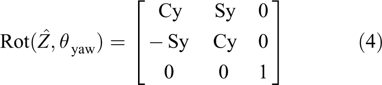
Figure 4 shows the structure diagram for the proposed 6-DOF platform, where P s, P m, P g, and P rp denote reference frames for the saddle, moving plate, global, and rotation module, respectively. Subsequently, the transform matrix from P s to P m coordinates can be expressed as
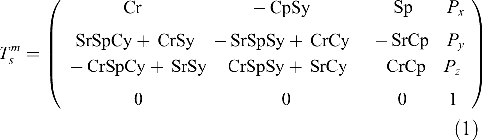
where r is the roll angle, p is the pitch angle, y is the yaw angle, Cr means cos(r), Cp means cos(p), Cy means cos(y), Sr means sin(r), Sp means sin(p), and Sy means sin(y).

The proposed 6-DOF platform structure. DOF: degrees of freedom; P s: saddle reference frame; P m: base moving plate reference frame; P g: global reference frame; P rp: rotation module reference frame.
Let

For given output variables for position (X, Y, and Z) and rotation angles (roll, pitch, and yaw), input variables for the displacement of the four linear actuators (d 1, d 2, d 3, and d 4) and rotation actuator angles (θ roll and θ pitch) are obtained from equation (2).
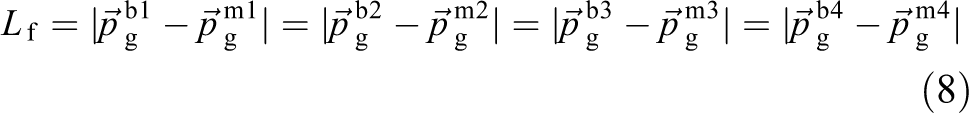
In Figure 5, the vector relationship of the ith chain from the global reference frame (Pg) to the moving plate reference frame (Pm) can be represented as

where the rotation matrix between the base plate and the moving plate and the local coordinates of the moving plate are, respectively, given by
and


Coordinates of the proposed mechanism: (a) description of the proposed mechanism, (b) the coordinates of the moving part, and (c) the coordinates of the base part. Pb1–4: position of the lower universal joint; Pm1–4: position of the upper universal joint; L f: length of the legs; L op: offset length of the moving plate; L ob: offset length between the base plate and the lower universal joint; L mx and L my: length of the moving part; L b: length of the base part.
The summation of the first and second terms on the right-hand side in equation (3) can be obtained as

where
Furthermore, the vector relation of each chain from the global reference frame (Pg) to the lower universal joint (Pb1, Pb2, Pb3, and Pb4) can be expressed as

Substituting equations (6) and (7) into equation (3) yields
where Lf is the fixed length of the legs and
Finally, solving for the displacement of the four linear actuators (d1, d2, d3, and d4), the inverse kinematic solution is obtained as
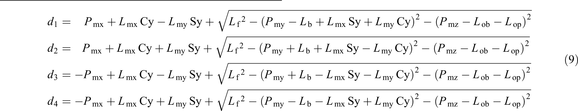
Figure 6 shows the flow by which the actuator control inputs are obtained by solving the inverse kinematics with motion trajectory data.

Control input generation.
Implementation of additional devices for realistic response and experience
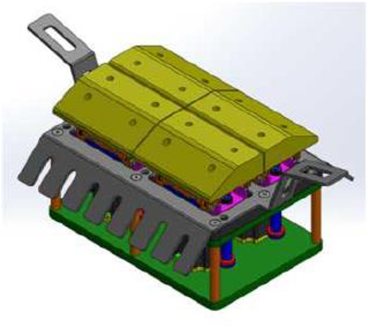
The sense of reality that a rider feels comes from the muscles and body movement of a horse, and so active saddle, neck, and tail mechanisms were developed for more realistic implementation. Figure 7 shows the active saddle design including four linear actuators to convey foot contact sensation to the rider. Figure 8 shows the active neck and tail mechanisms with two and one actuator, respectively. The active neck and tail respond to rider commands and intentions and enhance the feeling of communion when the simulator is used for therapy. Figure 9 shows the integrated system including the saddle, neck, and tail mechanisms.
Computer-aided design of the active saddle mechanism.

Active mechanisms for (a) neck and (b) tail.

Integrated system with neck, tail, and saddle.
Simulator controller
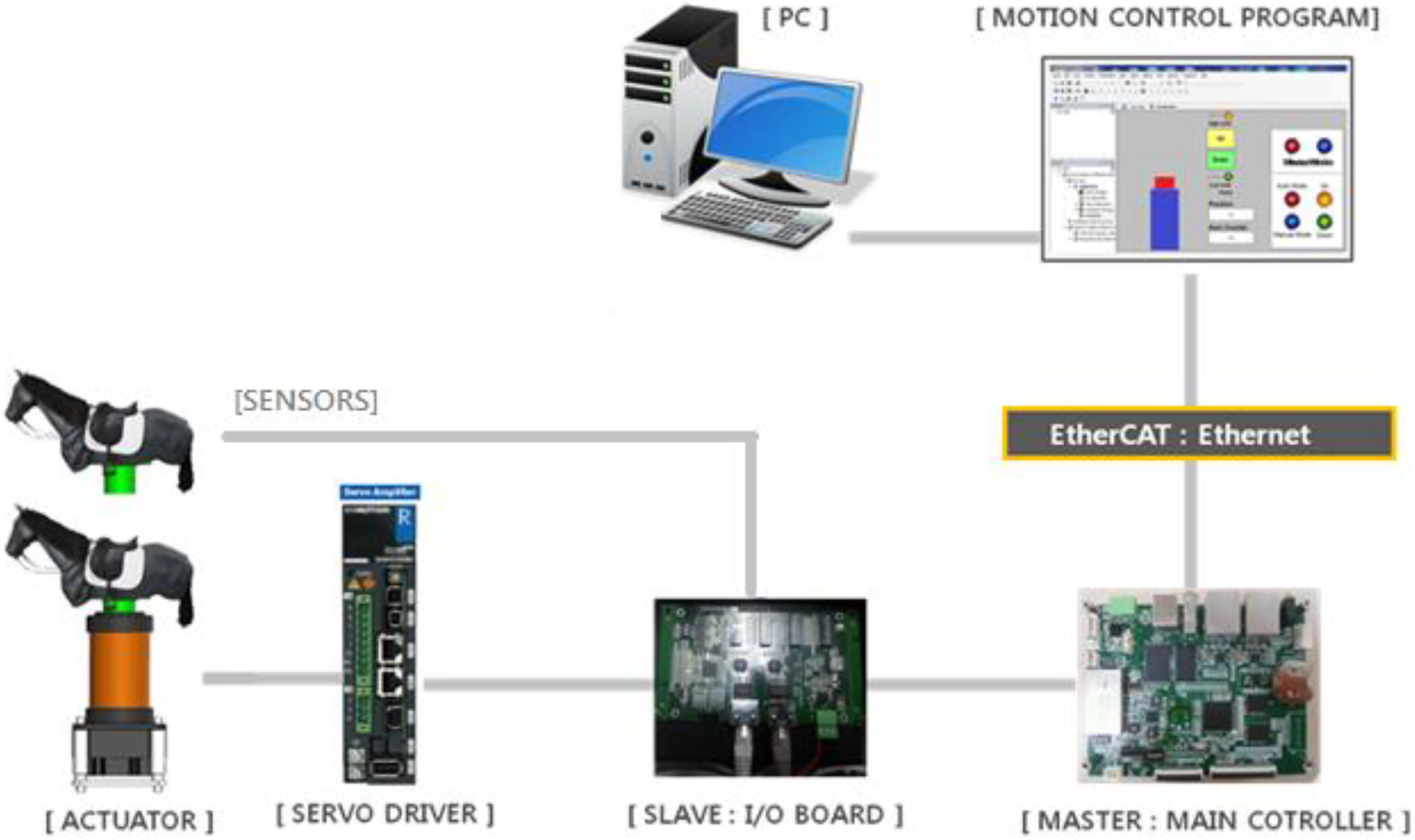
In order to control the simulator, a multi-actuator controller and I/O interface board based on an EtherCAT network was implemented, as shown in Figure 10. The EtherCAT network offers high data transfer speed (up to 100 Mbps), enabling high performance synchronized control of actuators and sensors. The robot platform was equipped with two beat, eight bridle, and four preparative sensors. The sensor signals were gathered by the I/O interface board and transferred to the master motion controller through the EtherCAT network. Figure 11 shows the configuration of the entire system and the robot, which has the appearance of a thoroughbred. In front of the robot platform, a large-sized screen was installed for visual effect.
The EtherCAT-based controller structure.

Final appearance of the robotic horse system.
Testing and experimentation
Motion trajectory generation
Horse gaits have long been analyzed using various sensors, such as cameras, inertia units, and optical markers to improve horse racing results. 18 –21 They are classified into walking, trotting, cantering, and galloping with leg sequences, as shown in Figure 12. The basic cycle time for each gait is approximately 1, 0.6, 0.4, and 0.32 s for walking, trotting, cantering, and galloping, respectively.
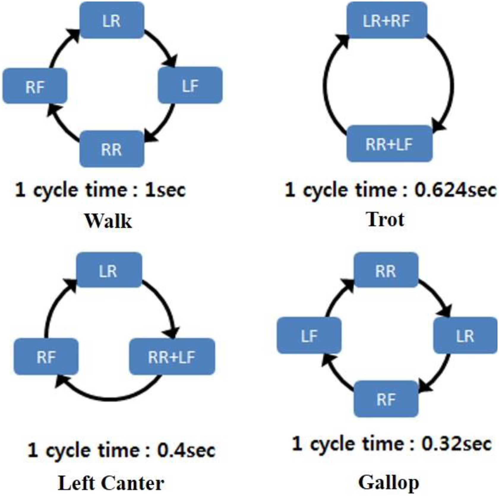
Horse leg sequences for different gaits. RF: right front foot; LF: left front foot; RR: right rear foot; and LR: left rear foot.
In this research, horse motion data for each gait were captured with optical markers attached to the horse. The motion data of the top of saddle were obtained by matching the captured data with a horse skeleton diagram, as shown in Figure 13. After normalizing, washout filtering, and fitting, which are standard processes in sports simulators, the basic motion trajectory function of the top of saddle was expressed as the sum of two sine functions. 22

where Ai , fi , and φi (i = 1, 2) denote amplitude, base frequency, and phase shift, respectively. This motion trajectory function is used to calculate the actuator control inputs instead of raw motion data. Figure 14 shows the final trajectories for x, y, z, roll, pitch, and yaw for the walking gait.

Motion data example (walking gait).

Final motion trajectory functions for the walking gait showing two strides: (a) X, Y, and Z positions and (b) roll, pitch, and yaw angles.
Gait transition
Typically, gait transition takes approximately 1.5–2.0 s. The trajectory function during gait transition was obtained by linear interpolation between the initial and final gait trajectory functions. Figure 15 shows the x position trajectory during gait transition.

Example of gait transition from walking to cantering.
Saddle motion generation
Time interval between foot contacts is approximately uniform for each gait, as shown in Figure 16, and the controller generates an actuator operation timing of active saddle based on these data. Table 2 shows the foot contact time interval for each gait.

Foot contact timing for the walking gait.
Foot contact timing.
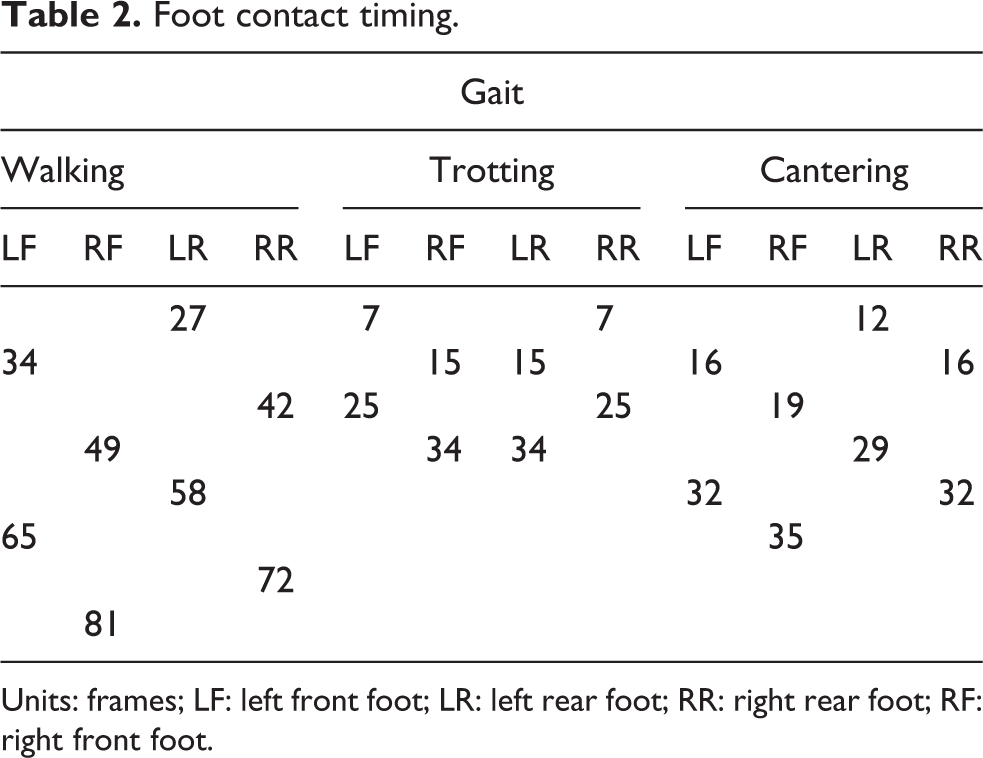
Units: frames; LF: left front foot; LR: left rear foot; RR: right rear foot; RF: right front foot.
Experts’ feedback and public test
We were unable to find a standardized method to measure the similarity between a real horse and a simulator from previous research, and so rather than a quantitative evaluation, testing by experts was conducted. Two official equestrian referees from the Korea Equestrian Federation participated, as shown in Figure 17. Evaluation of experts had been conducted three times a week over 3 months. The referees comprehensively evaluated motion trajectory, foot contact timing, and horse reaction, and the system was improved according to the feedback of the experts. The subjective similarity evaluated by the referees was low in the initial development phase. Referee and other expert feedback enabled the development of better motion trajectory and reaction compensation. After adjusting the motion trajectory of the simulator, the displacements and rotation angles of the saddle reference frame for three gaits—walking, trotting, and cantering—were measured, as listed in Table 3. These gaits have different speeds as well as motion trajectories, as listed in Table 2. Afterward, we conducted a survey of members who had experienced some kind of horse simulator from a sports club. Figure 18 shows the simulator setup for this testing. Sixty-eight members participated in the survey: 82.4% of the respondents answered that they were satisfied with the simulator and 92.1% said that using the simulator had an exercise effect. Thus, the developed simulator is considered to be sufficient for riding lessons and therapeutic use.

Korea Equestrian Federation referee testing the simulator.
Displacements and rotation angles of saddle reference frame for each gait.


Simulator system setup for the sports club member testing.
Conclusions
In this article, we present a new robotic horseback-riding system. The purpose of this research was to develop a more realistic and detailed simulator for riding lessons and equine-assisted therapy because similarity with a real horse enhances the educational and therapeutic effect. The proposed robotic system has an HKM structure consisting of a moving robot platform providing 4 DOF with a PUU-type structure, which enhances the workspace and improves the orientation capability and reduces the weight of the moving parts since the actuators are fixed on the base plate. An additional rotation module was mounted on the moving plate to generate roll and pitch motion and raise the center of rotation while keeping the moving platform height low. Moreover, active saddle, neck, and tail mechanisms were developed for realistic horse-like behavior. In this article, realistic motion does not mean fast and high-frequency motion, so the controller was implemented with commercial parts. The whole system has 13 actuators and several sensors, and an EtherCAT-based controller was implemented to control the system. Real horse motion data were captured, normalized, filtered, and fitted to provide the motion trajectory function for the top of the saddle and generate realistic motion control signals. The actuator operation signal for the active saddle was generated based on foot contact timing data. We conducted a survey of members who had experienced some kind of horse simulator from a sports club; 82.4% of the respondents answered that they were satisfied with the simulator, and 92.1% said that using the simulator had an exercise effect. Thus, the developed simulator is considered to be sufficient for riding lessons and therapeutic use.
Footnotes
Authors’ Note
Youngdae Lee is now affiliated to IPACT, Seoul, Republic of Korea.
Acknowledgements
This work was supported by the R&D program of the Korea Ministry of Knowledge and Economy (MKE) and the Korea Evaluation Institute of Industrial Technology (KEIT). Development of the 5-senses convergence sports simulator is based on a multi-axis motion platform.
Declaration of conflicting interests
The authors declared no potential conflicts of interest with respect to the research, authorship, and/or publication of this article.
Funding
The authors received no financial support for the research, authorship, and/or publication of this article.