
Abstract
In this article, a novel controller for a nonanthropomorphic exoskeleton robot was designed to reduce joint torque of its operator using the contact force between them. Since the joints of the nonanthropomorphic exoskeletons are not directly connected to those of the operator due to the difference between their kinematic structure, joint assistance is performed by transmitting the contact force on their coupling parts instead of transmitting the joint torque of the nonanthropomorphic exoskeleton directly into the human joint. Most of the previous studies have focused on reducing the measured contact force by moving the coupling parts or commanding the robot joint torque. On the contrary, the proposed method focuses on reducing the human joint torque, which is estimated by formulating inverse dynamics, by obtaining possible contact force solutions. The commanding torque of the nonanthropomorphic exoskeleton was calculated by inverse dynamics based on the model information. To verify the control performance of the proposed method, we have developed a simulation environment for a lower-limb nonanthropomorphic exoskeleton. When the coupling part was implemented to be rigid for an ideal case, the joint torque of the human model to perform the same motion was successfully reduced by the given torque reduction ratio. For a more realistic condition, a nonrigid coupling was also implemented as a virtual spring-damper system, and its effect on the control performance was demonstrated in the simulation.
Introduction
Most exoskeletons have been designed to be anthropomorphic and fit close to their operator’s body. 1 –3 Their joints are aligned to those of users, and assistive torque produced by actuators is directly transmitted into the corresponding human joints. 4 However, recent studies have found that misalignment between the two joints happens in many cases 5 –7 causing hyperstaticity and unwanted force around them. 8 –10 This affects the safety of the operator, especially the one with gait disabilities. 11 One of the reasons why aligning them is difficult to attain is that the human joints are mostly not simple hinges and have both rotational and translational degree of freedom (DOF) at the same time. 12
In order to solve this misalignment problem, several approaches have been proposed. One example for an upper-limb exoskeleton is to unbound both trunks of the robot and the user to remove kinematic constraints on the shoulder joint, when the robot is fixed on the ground. 1,13 Another example is to develop additional mechanisms with more DOFs at specific joints such as the shoulder 12,14,15 or the hip. 16,17 On the other hand, exoskeletons designed to be nonanthropomorphic are inherently robust against misalignment problems. 18 Parameters for their kinematic structure can be optimized to improve ergonomics, to reduce torque requirements, 19 or to increase backdrivability. 18 In case of anthropomorphic exoskeletons (AEs), they can deliver the same amount of assistive torque as the commanding torque to the user’s joints through contact force transmission. For nonanthropomorphic exoskeletons (NAEs), however, assistive torque is not the same as the commanding torque but decided by the kinematic relationship between the two.
Some of the control methods of AEs can be applied for NAE control at a high level. Since the end points of NAEs are mostly bound to the human body, their trajectories can be predetermined when the robot is used for the purpose of rehabilitation, 20 yet it is difficult to utilize in daily life for various operations. 21 If the user’s intention is estimated as an interaction force by force–torque (F/T) sensor measurements, the controller can derive commanding torque or modify end point trajectories to compensate for it. 22 Theoretically, the operator can barely feel the inertia of the robot using this method, yet in most cases joint torque is not actually reduced compared to the case without the exoskeleton, because the inertia and gravity of the operator are not compensated. Moonwalker was then developed to produce upward force on its pelvis to sustain a portion of the user’s body weight as well as reducing load on leg muscles and joints. 23 The robot may even switch to a control for reducing the interaction force, if necessary, while the robot follows the predetermined trajectory. 24,25 In order to apply the described methods to the NAE at a low level, however, it is necessary to establish how to calculate the contact force for assisting each joint torque of the user independently.
In this article, an NAE controller for multi-joint assistance using contact force transmission is proposed. The method focuses on obtaining possible contact force solutions to reduce the joint torque of the operator, while most of the previous works have focused on reducing the interaction force between the human and the robot by moving coupling parts or commanding the robot joint torque. For multi-joint assistance, it is necessary to assume that the DOF of the interaction force is greater than or equal to that of the target human joint and that the DOF of the robot joint is greater than or equal to that of the interaction force controlled. The assistive torque is determined to satisfy the given torque reduction ratios for each joint and is transmitted into the human body through the contact force on the coupling parts. The human joint torque is estimated by inverse kinematics and inverse dynamics of the model.
The proposed method was verified in simulations for a lower-limb NAE. The coupling part was first implemented to be rigid for an ideal case to see if the contact force actually produces the necessary assistive torque on the human joint. Then, for a more realistic situation, a nonrigid coupling was also implemented as a virtual spring-damper system, and its effect on the control performance was demonstrated by the simulation.
System configuration
Model construction
The proposed concept of multi-joint assistance can be applied into any kind of NAE that has contact force with DOFs greater than or equal to those of the operator’s joint. In this article, we constructed two 12-DOF lower-limb models of the NAE, and the operator for the simulation is shown in Figure 1. Their kinematics are different, and the robot leg is longer than the human leg as shown in Figure 2. The red and green arrows indicate right leg joint axes of the human and the robot, and the notations HY, HR, HP, KP, AP, and AR represent hip yaw, hip roll, hip pitch, knee pitch, ankle pitch, and ankle roll joint axes, respectively. The masses of the trunk, thigh, shank, and foot of the human are given as m tr = 39.48 kg, m th = 5.67 kg, m sh = 3.637 kg, and m fo = 3.61 kg, respectively. Similarly, the masses of the robot links are given as m tr,r = 11.87 kg, m th,r = 6 kg, m sh,r = 6 kg, and m fo,r = 3 kg. The right and left leg models are designed to be symmetrical, and their joint directions are the same. The joint damping coefficient is set to 1 Nms/rad for each robot joint and 0 for each human joint, respectively, and the joint friction coefficient is set to 0 for all joints. The human upper body image is a simple rendering attached to the trunk without any joint information.

12-DOF human and exoskeleton lower-limb models with different kinematics in the simulation. Their trunks and feet are combined with each other. Red and green arrows indicate leg joint axes of the human and the robot, respectively. DOF: degree of freedom.
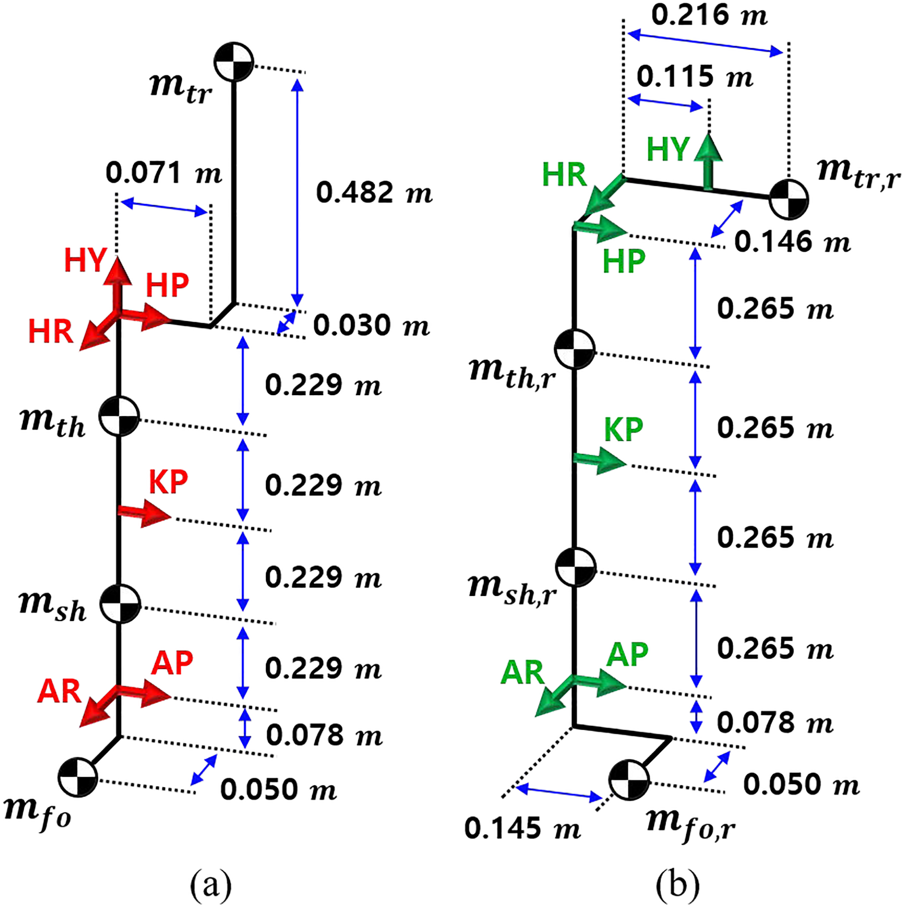
Kinematic structure of the right leg model of (a) the human and (b) the robot. The left leg model has symmetrical structure. The red and green arrows are the same as the joint axes explained in Figure 1. HY: hip yaw, HR: hip roll, HP: hip pitch, KP: knee pitch, AP: ankle pitch, and AR: ankle roll.
The NAE model has been designed to be used by tying its trunk and both feet to those of the human model as shown in Figure 1. We implemented the couplings using virtual wrench devices in the simulation, which will be explained later in the other section. On the other hand, they are generally implemented using straps attached to the robot body in real experiments, by which it is difficult to sustain large force tangential to the contact surface. In the experiment of Moonwalker, 23 the strap is wrapped around the bottom of the user’s hip to transmit upward force parallel to the human trunk, supporting the user’s body weight. Similar coupling methods can be applied for the experiment of the given NAE in the future.
Contact force for assistance
The couplings occur at the trunk and the feet, each of which has 6-DOF interaction force. For a single support phase (SSP), we derived the 12-DOF contact force on the trunk and the swing foot for assistance by formulating dynamics of both lower-body models with respect to their supporting foot frame fixed on the ground, as shown in Figure 3(a). In this way, the resulting 6-DOF ground reaction force (GRF) of the human model is determined and is theoretically equal to the interaction force to be generated between the human and robot supporting feet in the real experiment.

Contact force used for control depending on the contact state when the supporting foot frame is fixed on the ground. (a) During the SSP, 12-DOF CF on trunk and swing foot is used to transmit assistive torque to the target human joint. (b) During the DSP, 12-DOF lower body is thought of as two independent 6-DOF leg models. 26,27 Then, the resultant 6-DOF CF on trunk and 6-DOF redundancy in GRF) are used for assistance. SSP: single support phase; DOF: degree of freedom; CF: contact force; DSP: double support phase; GRF: ground reaction force.
On the other hand, if both feet of the lower-body model are fixed on the ground for a double support phase (DSP), a closed loop is created in the model tree, which can be difficult to be implemented in the simulation. Therefore, methods of dividing one lower-limb model into two leg models were studied in order to describe them in a fixed base frame, 26,27 as shown in Figure 3(b). To resolve 6-DOF redundancy in the 12-DOF GRF of both leg models, two effective masses supported by each leg are distributed by the ratio of the distance from each supporting foot to the center of mass (COM). Then, the quasi-static condition is applied to consider one 12-DOF lower-body model as two separate 6-DOF leg models, making the interaction force between the two trunks zero.
For each leg model, the total 12-DOF interaction force is applied to the trunk and the supporting foot. Since the 6-DOF GRF is determined by the distributed effective mass and the kinetic state of the model as shown in Figure 3(b), only the remaining 6-DOF contact force on the trunk can be utilized for 6-DOF leg joint assistance. Then, the 6-DOF torque solution of the robot is calculated to produce the required contact force, and the total 12-DOF commanding torque for the entire lower body is obtained by combining the two solutions of both leg models.
Dynamics of a human–robot coupled system
Most of the previous works for AE control formulated dynamics of a single integrated model of a human body and a robot. 2,28,29 However, since NAEs have different kinematics than the human body, they cannot be integrated into one model, and their dynamics have to be described separately, sharing only the same contact force at the coupling parts. In this article, all dynamic equations are formulated with respect to a fixed base frame, or a supporting foot frame, in the assumption that all the couplings are rigid. Also, a 12-DOF lower-body model is used for the SSP while each 6-DOF leg model is used separately for the DSP as explained before.
Then, equations of motion of the human model is given by

where q is the
The matrix Jc
is the
Similarly, equations of motion of the exoskeleton robot model is given by

where qr
is the
Control strategy
Figure 4 shows a block diagram of the overall control system. First, the joint value of the human model is estimated by solving inverse kinematics from the robot coupling part. Then, the contact force required for joint assistance is determined depending on the torque reduction ratio α. Finally, the torque solution of the exoskeleton robot is calculated to generate the desired contact force. In this article, the robot is assumed to be torque controllable. Therefore, the control input to the robot is joint torque

Block diagram of the overall control system depending on the coupling condition. H and R are the human and robot dynamics respectively, and C is the robot controller. α is the given torque reduction ratios for each joint. (a) When the coupling is rigid, the force exerted by the robot is directly transmitted to the human body. (b) When the coupling is nonrigid, the interaction force between two models is created as virtual spring-damper force, and force–feedback using F/T sensors is applied. F/T: force–torque.
The robot controller is designed to generate the contact force on the trunk and feet that is required to assist each human joint by the given torque reduction ratios α. Therefore, its control parameters are the torque reduction ratios α for each human joint. On the other hand, the human model is controlled to follow the predetermined motion by the proportional–derivative (PD) controller in the simulation. Thus, its controller parameters are PD gains, which are 5000–50 in this article.
All the equations in this section are formulated based on the assumption of rigid couplings. Then, the force produced by the robot is directly transmitted into the human body, acting as the assistive torque on the human joint as shown in Figure 4(a). In preparation for real experiments, however, nonrigid couplings were also implemented as virtual spring-damper systems in the simulation, which will be explained later in the other section. In this case, the contact force is determined by the relative displacement and velocity between both coupling parts, which may cause an error in the process of human posture estimation, as shown in Figure 4(b). Due to time delay and oscillation in force transmission, a simple force–feedback loop is added to the robot controller using small proportional and derivative gains for the nonrigid couplings.
Joint torque estimation
For assistance, the proposed method first estimates the human joint torque required for the current motion. A strain gauge 30 or a load cell 31 can be used for torque estimation, but when the robot is nonanthropomorphic, it is necessary to change the measurements back to human torque. In this article, a model-based method using inverse dynamics was used to calculate the torque required for the current motion from the joint angle, angular velocity, and the model information of the operator.
Since the kinematics of the NAE and the wearer are different, the joint value of the robot cannot be used as that of the human body. It has to be obtained by solving inverse kinematics of the position and velocity of the human coupling parts, which can be regarded as the same as those of the robot coupling parts if the connection is rigid, based on the model information. The proposed method can lead to estimation errors when the coupling is nonrigid, depending on the displacement of both coupling parts.
The procedure for obtaining the joint angle q from inverse kinematics is based on the previous work,
32
and the joint angular velocity

where
Then, the torque of the human joint

Note that
Contact force solution
Generally, the contact force required for assistance can be obtained in various ways depending on the user’s intention. In the proposed method, its desired value is determined to reduce the joint torque of the operator by the given torque reduction ratio α.
Now suppose that the joint torque to be generated by the wearer τ is α times the torque

The assistive torque is transmitted through the contact force in the coupling parts, and their relationship is given by

In equation (6), the DOF of the contact force, c, has to be greater than or equal to that of the assistive torque, n. If c is greater than n, the solution of
By combining equations (5) and (6), the equation for the desired contact force

Then, the solution of

where
Commanding torque of the robot
A solution of the commanding torque of the robot,

When the inertia of the robot,
Control of a human model in simulation
In this article, a joint space controller for the human model was designed to follow the given trajectory of the joint angle calculated by inverse kinematics of the trunk and feet position. By the assistive torque

Given the desired trajectory of the joint angle as

The terms
Then, by substituting equation (11) into equation (10), a solution of the human joint torque is given by

Note that α in equation (12) becomes an identity matrix when the human model moves without the robot.
Simulations
The simulation environment was developed using RoboticsLab [version v1.14], 33 a dynamics-based simulation software.
Implementation of couplings
The proposed controller transfers assistive torque to the operator using contact force on the coupling parts. Therefore, in order for the user to receive immediate assistance for the motion, the rigidity of the couplings has to be high to reduce the delay of contact force transmission. In this article, we first implemented an ideal situation where the couplings are perfectly rigid to see whether the distributed contact force can actually produce the desired assistive torque correctly.
When coupling parts of both models are directly connected in the model tree, a closed loop is created, which is difficult to be applied in the simulation environment of RoboticsLab. Therefore, the two models were kept separate, and wrench devices, which are virtual devices used to produce arbitrary force at the attachment point in RoboticsLab software, were used instead. The wrench device attached to the human coupling part directly generates the desired contact force, which is obtained in equation (8), and the other device on the robot coupling part produces the force of equal magnitude in the opposite direction, as shown in Figure 5(a). Since this virtual force cannot be used by the operator to drag the robot to the initial state, the motion of the coupling part was predetermined for the robot to compensate for its inertia by itself. If the rigid coupling was implemented directly rather than through wrench devices using other simulation tools, an undetermined motion could also be used for the same control method.

Implementation of two types of couplings in the simulation. The illustration shows that wrench devices, which can produce arbitrary force, are attached to both coupling parts at the swing foot. (a) In rigid coupling, the device transmits CF required for assistance directly to the human body and the robot. (b) In nonrigid coupling, the device generates virtual spring-damper force instead of the CF used in (a). CF: contact force.
On the other hand, the robot and the user’s body may be tied a bit loosely for comfort in reality, making the couplings nonrigid. In this case, the speed at which the contact force is transmitted to the operator is slowed down, and a positional difference occurs between both sides of the coupling part. We implemented the simulation of the nonrigid coupling as a virtual spring-damper system using the wrench devices as shown in Figure 5(b). Even if the robot applies the same force fr as in Figure 5(a) to the coupling parts, the force transmitted to the human body changes to the virtual spring-damper force, fs , instead of the necessary contact force, fc . The spring coefficients ks for high and low stiffness were set to 30,000 N/m and 10,000 N/m, respectively, so that the displacements are 1 and 3 cm when the interaction force is 300 N, which is about half of the human body weight. The damper coefficients kd for high and low stiffness were set to 300 N/m and 100 N/m, respectively.
Task configuration
In order to see whether the controller reduces the joint torque of the human by the given torque reduction ratio α, the torque with and without the robot were compared for the same motion in the simulation.
During the DSP, the trajectory of the trunk position is given going up and down by 20 cm for two cycles in the direction perpendicular to the ground or in the z direction, as shown in Figure 6(a). During the SSP, the trunk position is fixed and the trajectory of the swing foot position is given going up and down by 20 cm for two cycles in the z direction as shown in Figure 6(b).

Snapshots of one cycle of the human–robot coupled motion when the coupling is rigid. (a) During the DSP, the trunk position of the human model goes up and down by 20 cm in the z direction. (b) During the SSP, the swing foot position of the human model goes up and down by 20 cm in the z direction, while the trunk position is fixed. SSP: single support phase; DSP: double support phase.
Before verifying the results, it has to be confirmed that the supporting foot fixed in the simulation would not fall off the ground in the real experiment as well. Figure 7 shows the trajectory of the trunk and the swing foot used for the DSP and the SSP, respectively, and Figure 8 shows the resulting zero moment point (ZMP) 34 of the supporting foot measured by the F/T sensors in the model. Since the ZMP is inside the foot boundary, the moment exerted on the supporting foot is fully compensated by the GRF. Thus, planar contact between the foot and the ground can be maintained for the given motion in both the simulation and the experiment. Note that only the ZMP of the right supporting foot is shown in Figure 8(a), since the ZMP of both feet are symmetrical and that the ZMP with and without the robot are different due to the weight of the robot model.
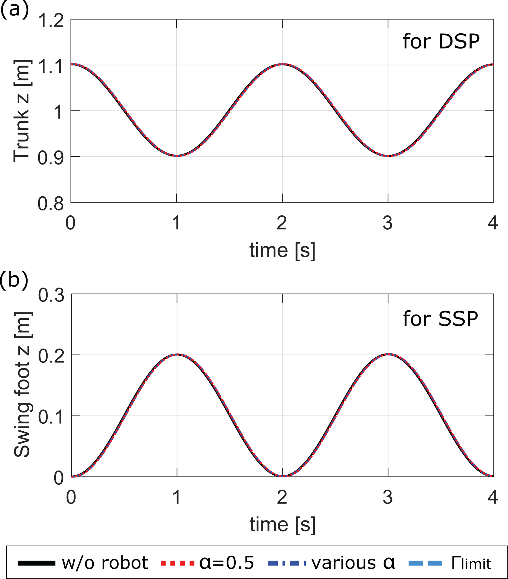
The trajectory of the human model for two cycles depending on the torque reduction ratio α of the proposed controller. (a) The trunk trajectory in the z direction for the DSP. (b) The swing foot trajectory in the z direction for the SSP. SSP: single support phase; DSP: double support phase.

The ZMP trajectory of the right supporting foot of the human–robot coupled model (a) during the DSP and (b) during the SSP. In both cases, it lies within the foot boundary, represented as a blue box. ZMP: zero moment point; SSP: single support phase; DSP: double support phase.
In the simulation, three types of human joint assistance were implemented by determining the corresponding torque reduction ratio α. One way is to set all diagonal components of the α to 0.5 so that the torque of all the human joints when wearing the robot becomes half of the torque when not wearing it, which is the case of

Equation (13) was calculated by the robot controller every tick, and the magnitude of the torque limit for all the joints was given as 25 Nm.
Joint torque variation
When the coupling is rigid, the joint torque of the human has to be reduced to exactly α times, since no positional difference between both coupling parts exists, and the contact force required for assistance is directly transmitted into the human body.
Figure 9 shows the resulting joint torque of the human model depending on the choice of α in the robot controller. As expected, the torque required for the same motion was exactly halved at

Torque variation depending on the torque reduction ratio α, when the coupling is rigid (a) during the DSP and (b) during the SSP. In case of various α, the components of α corresponding to the AR, AP, KP, HP, HR, and HY are 1.0, 0.9, 0.8, 0.7, 0.6, and 0.5. In case of
Figure 10(a) shows the joint torque of the human model for the same motion when the couplings are nonrigid. The torque reduction ratio α was set to 0.5 for all the joints, and the virtual spring-damper coefficients ks and kd were set to 30,000–300 N/m for high stiffness and 10,000–100 N/m for low stiffness, respectively. Due to the nonrigidity of the couplings, both time delay and oscillation occurred in contact force transmission. In addition, human posture was not estimated accurately by inverse kinematics because of the displacement between the human and robot coupling part, leading to the desired contact force error as shown in Figure 10(b). Therefore, the torque of the human model converged to a slightly different value from the torque without the exoskeleton robot. Note that the contact force in the z direction is relatively high, since the motion is mostly generated in the direction of gravity.
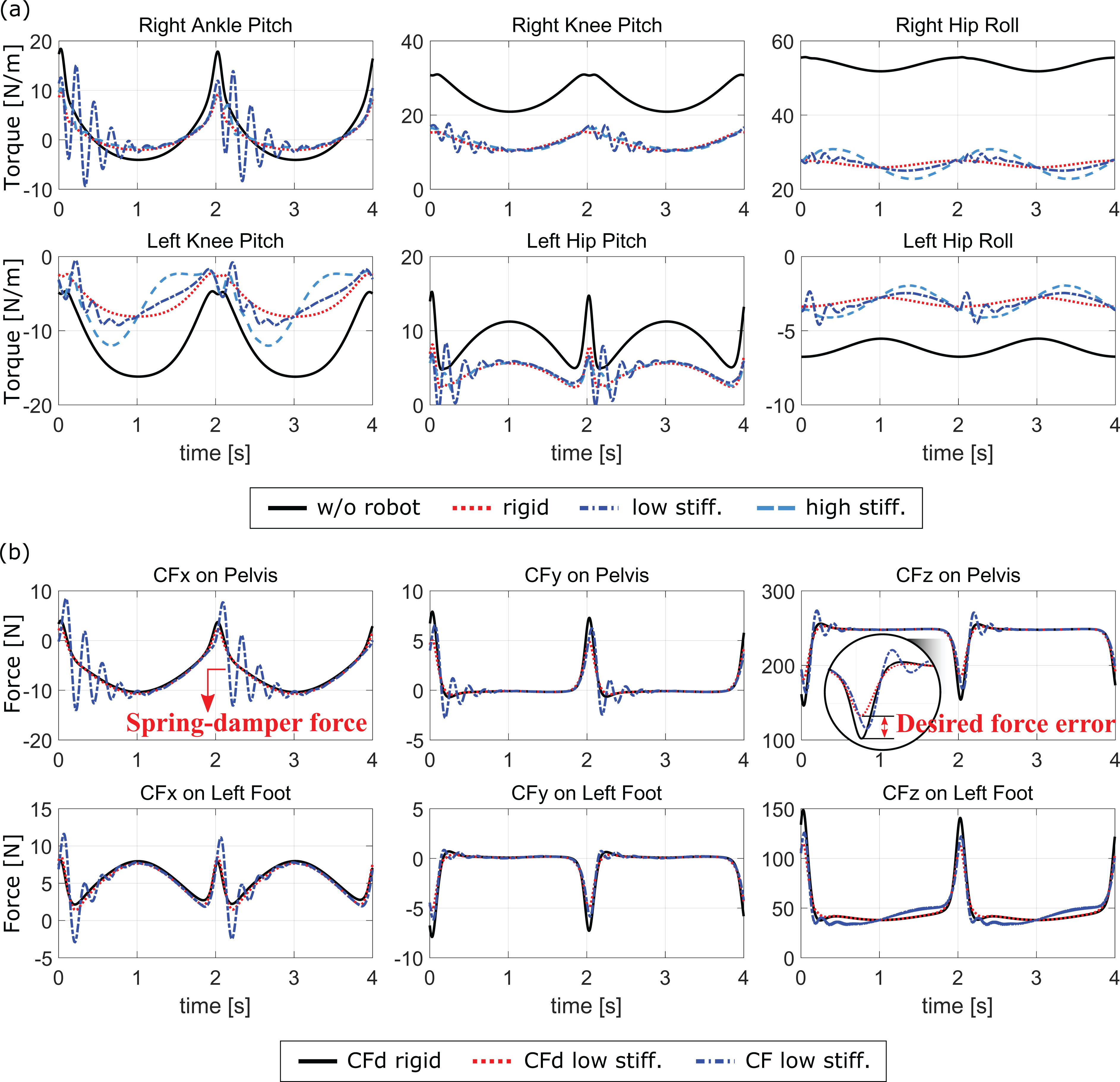
The simulation results for the SSP when the coupling is nonrigid. The virtual spring and damper coefficients
In order to compare the control performance according to the stiffness of the couplings, the error rate (ER) of the human joint torque when α is 0.5 for all the joints is calculated as follows

where
Conclusion
In this article, we proposed a method for NAEs to reduce joint torque of the operator using contact force transmission. The possible solution of contact force was obtained to satisfy the given torque reduction ratios α for each joint, while the previous works have focused on reducing the measured contact force between the coupling parts. The control performance was verified in simulations for a lower-limb NAE, where both rigid and nonrigid coupling were implemented for an ideal case and for a realistic condition, respectively. The human joint torque was successfully reduced to α times when the coupling was rigid, and the torque error within 10% occurred when the coupling was nonrigid.
The performance of the controller can be reduced by two main factors. One is the error in the model information. Since joint torque estimation and inertia compensation require inverse kinematics or inverse dynamics of both human and robot model, even a small model error may degrade control performance. The other is low stiffness of the couplings. The assumption that the position of the human and robot coupling parts are the same, which is used in solving inverse kinematics, can cause torque estimation errors in nonrigid coupling condition. Later, this assumption can be modified or other torque estimation methods can be used instead. Also, time delay and oscillation occurs in contact force transmission, which is not considered for calculation of the desired contact force in this article.
In real experiments, several problems may arise. One is that the delay in F/T sensor feedback and joint friction can affect the performance of the robot, especially when the robot is at low velocities such as when the robot starts its motion and changes its directions. Another is that accurate F/T measurements at the coupling part between the robot and human body can be difficult. Therefore, the device or coupling methods have to be investigated for them. Finally, the estimation of joint angular acceleration has noise and delay. This issue also has to be assessed and investigated with the real robot experiments.
Future studies will also apply various optimization conditions to the solution of contact force or commanding torque using robots with more DOFs. For example, a contact force solution can be obtained to satisfy a given torque reduction ratio while minimizing the force applied to a particular part of the human body. We are currently analyzing the stability of the system and will add the results in the next study.
Footnotes
Declaration of conflicting interests
The author(s) declared no potential conflicts of interest with respect to the research, authorship, and/or publication of this article.
Funding
The author(s) received no financial support for the research, authorship, and/or publication of this article.