
Abstract
The early phase of extremity rehabilitation training has high potential impact for stroke patients. However, most of the lower limb rehabilitation robots in hospitals are proposed just suitable for patients at the middle or later recovery stage. This article investigates a new sitting/lying multi-joint lower limb rehabilitation robot. It can be used at all recovery stages, including the initial stage. Based on man–machine engineering and the innovative design for mechanism, the leg length of the lower limb rehabilitation robot is automatically adjusted to fit patients with different heights. The lower limb rehabilitation robot is a typical human–machine system, and the limb safety of the patient is the most important principle to be considered in its design. The hip joint rotation ranges are different in people’s sitting and lying postures. Different training postures cannot make the training workspace unique. Besides the leg lengths and joint rotation angles varied with different patients, the idea of variable workspace of the lower limb rehabilitation robot is first proposed. Based on the variable workspace, three trajectory planning methods are developed. In order to verify the trajectory planning methods, an experimental study has been conducted. Theoretical and actual curves of the hip rotation, knee rotation, and leg mechanism end point motion trajectories are obtained for three unimpaired subjects. Most importantly, a clinical trial demonstrated the safety and feasibility of the proposed lower limb rehabilitation robot.
Introduction
According to the statistics from the China Disabled Persons’ Federation, in 2010 the number of patients with limb disorder was about 24.72 million in China. There are about 1.5 million people being affected by a stroke every year, and most stroke patients lose their walking ability. 1,2 The problem of aging population is becoming more and more serious and the number of people over 60 was over 220 million in 2016. 3 The elderly are the main risk group for cerebral vascular disease and stroke. These diseases may also cause limb motor dysfunctions to elderly people. 4 –7 Meanwhile, due to the occurrence of traffic accidents and natural disasters, the number of patients with nerve damage and limb injuries increases. 8 The patients with physical disabilities have difficulty in independently performing daily life activities. 9,10 The treatment for limb motor dysfunctions requires a lot of manpower, material, and financial resources, which creates an enormous burden on society. Robotic systems have been applied to the rehabilitation field. 11,12 They are highly accurate, can work for very long periods of time, can automatically feedback the progress, and perform a wide range of forces and motions. 13 Thus practically applicable rehabilitation robots are urgently needed. At present, the research on lower limb rehabilitation robots (LLR-Ros) has become a hot spot, 14 –18 and several LLR-Ros have been developed. They can be divided into single degree of freedom rehabilitation robots, wearable rehabilitation robots, suspended rehabilitation robots, and sitting/lying rehabilitation robots. The effect of a single degree of freedom rehabilitation robot is not good as it just can realize only one rehabilitation movement. The wearable rehabilitation robot would be adopted when the patients have high abilities to walk independently in the later recovery stage.
Wang et al. proposed a suspended rehabilitation trainer and a patient-driven control strategy to motivate patient participation. 19 The Lokomat, 20,21 developed by Hocoma AG (Volketswil, Switzerland), is the first driven gait orthosis that helps to improve the walking movements of patients who are gait-impaired. Colombo et al. 22 gave a detailed description of the Lokomat. Other typical suspended gait trainers include LOPES, 23,24 RAGT, 25 Haptic Walker, 26 LokoHelp, 27,28 and Gangtrainer GT I. 29
Carleton University made a Virtual Gait Rehabilitation Robot (ViGRR) for bedridden stroke patients. It can provide the average gait motion training as well as other targeted exercises such as leg press, stairstepping, and motivational gaming. 30 Swortec company made the most advanced sitting gait trainer, the MotionMaker. 31 –33 The system is composed of two robotic orthoses comprising motors and sensors, and a control unit managing the transcutaneous electrical muscle stimulation with real-time regulation. Yıldız University of Science and Technology in Turkey made a sitting/lying gait trainer, the Physiotherabot, helping patients do passive training and active training. 34 A wire-driven leg lying rehabilitation system was developed by the National Institute of Advanced Industrial Science and Technology of Tsukuba. 35
Although researchers have developed many kinds of LLR-Ros, there are not many robots that are suitable for patients at all injury levels. Most of the suspended gait trainers are suitable for patients in their middle and late stages of recovery who are already able to stand up. Stroke patients would recover better, if they start rehabilitation training earlier after the stabilizing state of the illness. 36 So the sitting/lying rehabilitation trainer has a strong advantage. This article proposes a new applicable sitting/lying LLR-Ro. This innovative mechanism design makes it different from the other sitting/lying rehabilitation robots. The mechanical structure comparison with the other sitting/lying lower limb trainers is shown in Table 1.
Mechanical structure comparison with other sitting/lying trainers.

Besides, this article first proposes a variable workspace of the sitting/lying LLR-Ro. Based on the variable workspace, three trajectory planning methods are put forward, including the largest circle trajectory planning, the largest linear trajectory planning, and the arbitrary curve trajectory planning. The largest circle trajectory planning and the largest linear trajectory planning allow the patient’s joints to move with the largest rotation range. Based on the level of their recovery, the arbitrary curve trajectory planning allows patients to design the trajectory by themselves to improve the initiative of the patients.
Innovative design of the LLR-Ro
Based on the theory of innovation and modularity, the LLR-Ro is mainly divided into the left leg mechanical module (LLMM), the right leg mechanical module, the mobile seat, and the control box (as shown in Figure 1). There are four universal casters installed under the mobile seat, so the seat could be separated from the LLR-Ro to transfer the patient from the bed to the LLR-Ro or vice versa. The LLMM is symmetric with the right one. The workspace of the LLMM needs to meet the demand of patients with a height ranging from 1500 to 1900 mm. Three joint rotation ranges of motion of the LLMM, which are consistent with patient legs, can be achieved. However, the below three joint rotation ranges are shown in Table 2. They are just designed to satisfy the patient’s daily activity needs.

Prototype of the LLR-Ro. LLR-Ro: lower limb rehabilitation robot.
Three joint rotation ranges of motion.

Foot assembly structure design
The foot assembly consists mainly of the ankle joint drive assembly, the ankle rack, and the plantar plate assembly as shown in Figure 2. The foot assembly has two protection modes, namely the limit switch protection mode and the mechanical protection mode, which make it highly reliable and safe. The limit switch is installed at the ankle joint extreme position. When the foot assembly rotates almost at the ankle joint extreme position, the control circuit would be cut and the robot stops the mechanical leg motion to protect the patients from being harmed. The motor encoder is utilized to measure the ankle joint rotation’s angle. There is a pull-press sensor installed on the plantar plate assembly. During the rehabilitation training, while the patient’s foot is on the pedal of the LLR-Ro and the ankle joint rotates, the pull-press sensor can get the voltage signals which can be transformed into plantar force values. This design can acquire the ankle torque based on the force the patient’s foot applies on the robot. It reduces the dimensions and the costs, in comparison with a structure that adopts a torque sensor, as most of the small dynamic torque sensors are more expensive than the force sensors.

Foot assembly structure design: (a) the ankle joint drive assembly and (b) the plantar plate assembly.
Calf assembly structure design
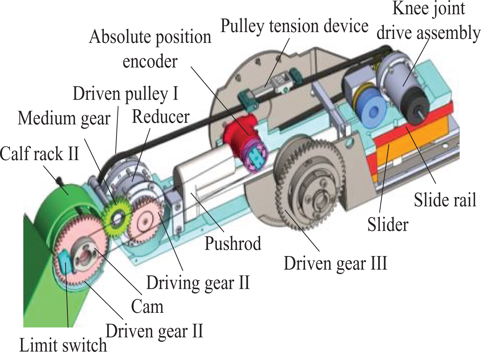
The calf assembly contains the calf length adjustment mechanism, the torque measurement mechanism (see Figure 3), the knee joint drive chain, the calf rack I, the calf rack II, the limit switch and the absolute position encoder (see Figure 4). The calf assembly design also considers two protection modes to prevent the patient being second-harmed. The absolute position encoder, which is installed to measure the knee joint rotation angle directly, can eliminate measuring errors and make the training trace more accurate. One end of the torque sensor is installed on the calf rack II and the other end is installed on driven gear. And both the torque sensor and the driven gear are connected with bearing inner rings. The bearing outer rings are fixed on the thigh rack II. The design of the torque sensor installation structure ensures that it only measures the torque without the axial force and the radial force and no fictional moment.

Calf assembly structure design: (a) calf length adjustment design and (b) knee torque measurement design.
Thigh assembly structure design.
Thigh assembly structure design
The thigh assembly includes the thigh length adjustment mechanism, the swinging frame, the torque sensor, the absolute position encoder, and the hip drive chain (see Figure 5). The working principle of the thigh length adjustment mechanism is as follows. One end of the pushrod is connected to the thigh rack, while the other end is connected to the swinging frame; the slider is installed on the thigh rack and the slide rail is installed on the swinging frame; so when the length of the pushrod is changed, the thigh rack is in motion with respect to the swinging frame. The other merit of the thigh assembly design is that the knee joint drive components are installed at the rear end of the thigh assembly, so the weight of the knee drive components acts as a balance weight and reduces the hip joint drive power.

Mechanical leg structure design.
Mathematical model of LLR-Ro’s variable workspace
Relationship between the terminal position and the joint angles
This article defines the length of the thigh as l1 and the length of the calf as l2. The linkage model of the LLR-Ro can be simplified as shown in Figure 6, O represents the hip joint, O1 represents the knee joint, O2 represents the ankle joint, θ1 and θ2 represent the rotation angle of the joints, and the rotation shaft center of the hip joint is the origin of the coordinate system. As the lengths of the thigh and the calf are much longer than the foot, in the following trajectory planning methods, the ankle joint motion is designed separately to obtain large ranges of motion, so here O2 is chosen as the end point, which can be expressed as

The linkage model and the coordinate system establishment.
Solution of the variable workspace mathematical model
As the LLR-Ro is a typical human–machine system, the limb safety of the patient is the most important principle to be considered in its design. There is a safety angle between the thigh and the upper part of the body in both sitting and lying posture training as shown in Figure 7. If the upper part of the body is at the dotted line position and the thigh is at the full line position, it would bring the patient a secondary damage. So the sitting and the lying posture training have different training workspaces, and the patient’s training safety is a high priority, the variable workspace of the robot is proposed.

Training posture sketch of the patient.
Meanwhile, for a particular patient, during different recovery stages, the LLR-Ro allows to adjust the rotation angles’ limits of the hip and knee joints according to the physician’s recommendations, so the workspace area of the LLR-Ro changes. The trajectory planning should be carried out in the workspace, so the first step is solving the variable workspace. Using the geometrical method to get the solution is simple and pictorial. The workspace consists of four circle arcs as shown in Figure 8. The point O represents the hip joint, θ11 is the minimum angle of the hip joint, θ12 is the maximum angle of the hip joint, θ21 is the minimum angle of the hip joint, and θ22 is the maximum angle of the hip joint. The curve 

The variable workspace of the robot.
In equation (2),
The figure
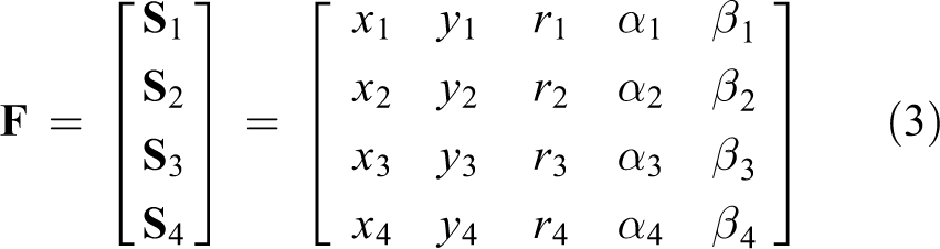
where
Solution of different trajectory modes in variable workspace
Three training trajectory planning modes are proposed, including the largest circle trajectory mode, the largest linear trajectory mode, and the arbitrary curve trajectory mode. The largest circle trajectory mode and the largest linear trajectory mode are adopted to ensure the largest rotation range for the movements of the patient’s joints, and as a result, the effectiveness of the rehabilitation process on the patient increases. The arbitrary curve trajectory mode can meet the needs of all users and make the training more customizable, as it allows patients to design the trajectory by themselves based on the level of their recovery. Based on the degree of their lower limb injury, patients choose their training trajectories, as different training trajectories can help the patient recover different joint ranges of motion. All training trajectories consisted of the joint ranges to satisfy the patient’s daily activity needs.
Solution of the largest circle trajectory mode
For the workspace variability and randomness, the patient has many circle trajectories in it. The largest circle trajectory mode is proposed. This mode contains a series of largest circle trajectories to satisfy patient-demanded joint motion. The trajectories can be divided into four domains. The circle

The training trajectories in the largest circle trajectory mode.
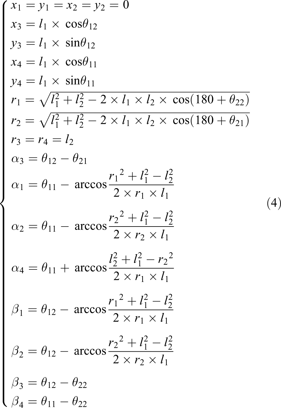
The trajectory can be solved through the geometrical method in the following equation

The trajectories are verified through the computer simulation. The thigh length and the calf length are 420 and 330 mm, respectively. The maximum hip joint and the minimum hip joint are 70° and 10°, respectively. The maximum knee joint and the minimum knee joint are −10°and −110°, respectively. The least radius of the circles is 50 mm and the radius increases by 5 mm. From the simulation, the workspace and circle trajectories are achieved, as shown in Figure 10.

The largest circle trajectories verified through the simulation: (a) the solution of the circle O13, (b) the solution of the circle O24, (c) the solution of the circle O12, and (d) the solution of the circle O34.
Solution of the largest linear trajectory mode
Picking the start point is important to get the largest linear trajectory. Based on the patient joint motion range natural recovery situation, the point K is selected as the start point, which is the intersection of the circles

The line KM in the workspace.
The trajectory can be expressed by a matrix

where

In formula (6),
In equation (6), xM is a variable. θKM increases by 5°. The trajectories are verified through the computer simulation, as shown in Figure 12.

The simulation of the KM.
Solution of the arbitrary curve trajectory mode
The arbitrary curve trajectory mode implies that patients can draw the training trajectory in their workspace by themselves. The patient draws curves on the screen. Then the robot will deal with the curves automatically and estimate whether they are in the workspace. If the curves are beyond the patient workspace, the curves need to be modified. If not, the robot will save the curves and help the patient do the recovery training exercises. The user can draw regular figures (circular or linear trajectories) and irregular figures as shown in Figure 13.

The simulation of the arbitrary curve trajectory planning: (a) the circular trajectory, (b) the linear trajectory, and (c) the irregular figure trajectory.
For the circular trajectory, the user clicks in the workspace, then the point will be defined as the center. As the mouse moves, the coordinates of the end point will be obtained. The distance between the center and the end point is the radius of the circle trajectory. For the linear trajectory, the point the user clicks in the workspace is set as the starting point of the trajectory, and the second click point is the end point.
For the irregular figure, the clicks will be set as the waypoints. Waypoints are connected with each other through some lines. Those lines compose an irregular figure and the figure will be processed to be a smoothed one. For example, there is an irregular figure with several waypoints as shown in Figure 14. Waypoints would be connected by the curves meeting the following conditions. The first curve connects the first waypoint and the second waypoint and the last curve connects the last waypoint and the second-to-last waypoint through the quartic polynomial interpolation method. The curves connect the rest of the points through the trinomial interpolation method.

The irregular figure being processed to be smooth by the computer.
In order to ensure the continuous velocity condition, the velocities of the first waypoint and the last waypoint are zero. The speeds of the other adjacent two points are equal. To ensure the continuous acceleration condition, the acceleration of the first waypoint and the last waypoint is zero. The acceleration of the other adjacent two points is equal. The trajectory after interpolation is obtained as shown in Figure 14. From Figure 14, it can be found that the trajectory after interpolation is similar to the trajectory before interpolation, but it is smoother than the trajectory before interpolation.
Preliminary experimental trials on healthy subjects
In order to verify the trajectory planning of the robot, an experiment has been conducted with three normal subjects. Their heights, calf lengths, and thigh lengths have been recorded as shown in Table 3. The hip joint ranges and knee joint ranges of the subjects are limited to mimic the patient status, as shown in Table 4.
Physical size of the subjects.

Joint ranges of the subjects.

Before the clinical test, approval for all studies was obtained from Yanshan University ethics committees, and all subjects gave written informed consent. According to the subjects’ joint ranges and leg lengths, the robot calculated the subjects’ workspace in the largest circle trajectory mode. In this experiment, the training trajectories are chosen tangent to the boundary curves

The experimental process of subject II.
Theoretical trajectories of the subjects’ ankle joint axis are shown in Figure 16. Based on the theoretical trajectories, the robot calculated LLR-Ro knee joint theoretical motion curves and hip joint theoretical motion curves as shown in Figures 17(a) and 18(a). The robot also obtained LLR-Ro hip joint actual motion curves and knee joint actual motion curves through the absolute position sensors as shown in Figures 17(a) and 18(a). The errors of the hip and knee joint actual motion data with theoretical motion data are shown in Figures 17(b) and 18(b). Actual trajectories of the subjects’ ankle joint axis are calculated through equation (1) as shown in Figure 16. The leg end point motion error curves of three subjects are obtained as shown in Figure 19.
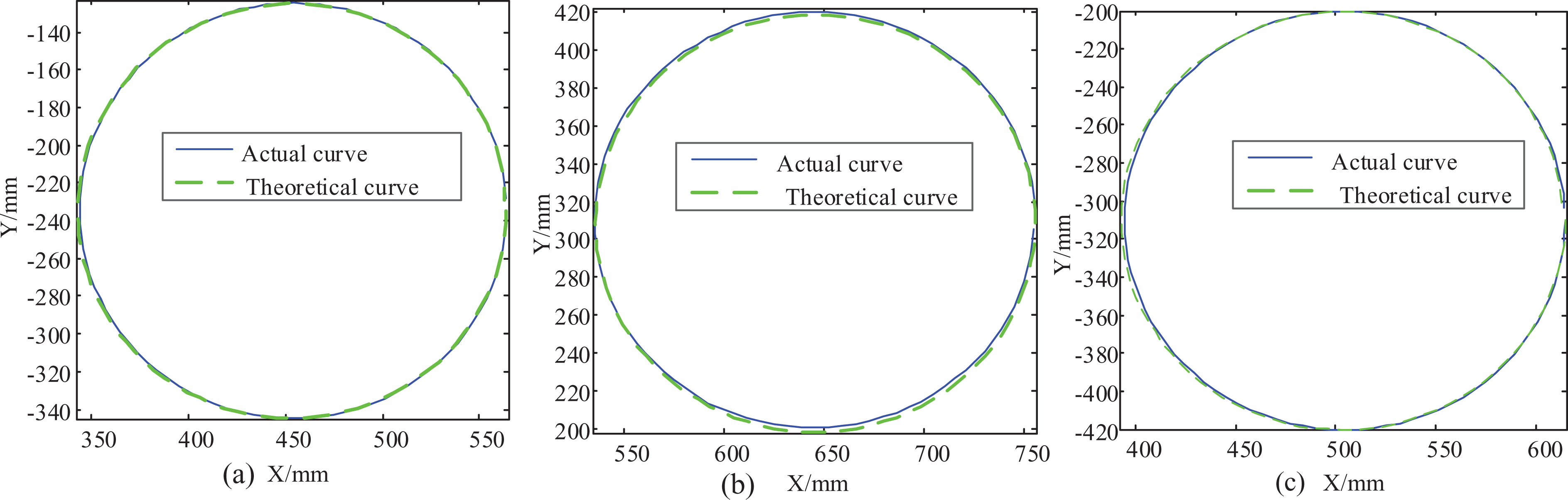
The leg end point motion curves of the three subjects: (a) the leg end point motion curves of subject I, (b) the leg end point motion curves of subject II, and (c) the leg end point motion curves of subject III.

Theoretical and experimental curves of knee rotation: (a) theoretical and experimental knee rotation curves of the three subjects and (b) the knee joint rotation errors of the three subjects.

Theoretical and experimental curves of hip rotation: (a) the theoretical and experimental hip rotation curves of the three subjects and (b) the hip joint rotation errors of the three subjects.

The leg end point motion error curves of the three subjects: (a) the leg end point motion errors along x-axis, (b) the leg end point motion errors along y-axis.
Clinical trials of LLR-Ro
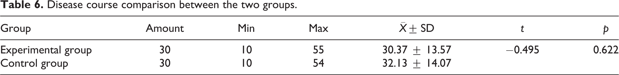
In order to test the feasibility and safety of LLR-Ro, 60 stroke patients with lower limb dysfunction in the First Affiliated Hospital of Xinxiang Medical College were chosen to carry out the clinical trial. The trials lasted from January 19, 2015 to April 8, 2015. Before the clinical test, approval for all studies was obtained from local ethics committees, and all subjects or their legal representatives gave written informed consent. According to the experimental requirements, patients were divided into two groups, named the experimental group and the control group. Each group consisted of 30 people. Basic information of the two groups was recorded, including age and disease course. The age of the two groups was compared as shown in Table 5 and the disease course of the two groups was compared as shown in Table 6. The comparisons between the two groups were similar (p > 0.05).
Age comparison between the two groups.

Disease course comparison between the two groups.
The experimental group did the rehabilitation training with LLR-Ro, while the control group did the training through the other quality LLR-Ro (YKXZFK-9, Xiangyu Medical Equipment Co., Ltd [Anyang, China]). The speed and the motion range of the robots were set slow and small, respectively, at the start of the rehabilitation training. Then they would be set faster and larger based on the patients’ rehabilitation condition and the physician’s suggestion. The patients in both groups attended the rehabilitation training one time a day and each time 30 min. The patients rested on Sunday to get stamina for the next week. Each patient’s rehabilitation training lasted 4 weeks. The patients were assessed with Clinical Neurological Functional Deficit and Fugl-Meyer assessment before and after treatment. The clinical trial research data were recorded as shown in Tables 7 and 8.
The comparison of Clinical Neurological Functional Deficit scores before and after treatment.

The Fugl-Meyer assessment scores in the two groups before and after treatment.

The rehabilitation physicians finally obtained the clinical trial results of LLR-Ro. Through t-test, there were significant differences with regard to Clinical Neurological Functional Deficit and Fugl-Meyer assessment in the two groups before and after treatment (p < 0.001). The treatment result of the experimental group is similar to the control group (p > 0.05). This verifies that it is feasible to help patients doing rehabilitation training through the LLR-Ro. In the whole clinical trial, patients in the two groups had no adverse events. The adverse event rates were the same, both were 0.00%. Therefore, the clinical tests showed that the use of LLR-Ro was safe.
Discussion
Compared with the present sitting/lying rehabilitation robots, LLR-Ro could adjust the length of the mechanical leg electrically through an innovative design of the length adjustment mechanism. This merit is well received by the rehabilitation physicians as they do not have to adjust the mechanical leg length by hands to fit patients with different heights. Meanwhile, the knee drive motor is installed at the rear end of the thigh assembly, and this design needs the hip joint driving torque to be smaller than the motor installed at the front end. The operation life of the hip motor could be improved. Besides, the torque sensor is installed at each joint axis and measures the hip/knee torque directly without intermediate transmission. This design could improve the torque measurement accuracy.
To guarantee the safety of patients, a variable workspace conception is first proposed, and three training trajectory planning modes are proposed and simulated in the variable workspace. Preliminary experimental trials on healthy subjects are conducted to verify the science of the trajectory planning methods. Figure 16(a) to (c) tells that the trajectories are not at the same position for people of different heights designed to train through a same size circle. Figure 19 tells that the actual trajectories are similar when compared to the theoretical ones. The errors are quite small, and the LLR-Ro can meet the requirements of clinical application. In Figures 17(a) and 18(a), both the hip joint and the knee joint motion ranges of the subject I are larger than the subject III’s in the same trajectory size. However, both the hip joint motion ranges contain 0°–24° and both the knee joint motion ranges contain −120° to −85°, having a large interaction. The hip joint motion range of subject II is 24°–46.5°and the knee motion range of subject II is −95° to −55°, both the hip joint and knee joint motion range interactions with subject I are very small. So the joint training ranges generated by the LLR-Ro with the largest circle trajectory mode could satisfy the needs of the patients with different joint range requirements. From Figures 17(b) and 18(b), all the absolute values of the errors are smaller than 0.3°. It tells that LLR-Ro has a high position control accuracy used for patient training. Besides, all the knee joint motions of the three subjects have the largest error around 8 s. That is led by the gear clearance at the knee joint. The errors are quite small, and the LLR-Ro can meet the requirements of clinical application. Those methods could generate all the trajectories proposed on the other sitting/lying rehabilitation robots.
Only few of the sitting/lying LLR-Ros undergo clinical trials. LLR-Ro has completed 60 clinical trials and it is feasible to help patients doing rehabilitation training through the LLR-Ro. However, the quantity of clinical trials needs to be increased in the future to verify the absolute safety and useful recovery of LLR-Ro. Besides, the recovery effect comparison between the LLR-Ro and the suspended rehabilitation robots, the recovery effect comparison between the LLR-Ro and the other sitting/lying rehabilitation robots will be researched in the future.
Conclusions
A new sitting/lying multi-joint LLR-Ro is developed to help people with lower extremity injuries in all recovery stages. It has a great advantage relative to the suspended LLR-Ro. The innovative mechanism design of the LLR-Ro also makes it different from the other sitting/lying rehabilitation robots. The idea of the variable workspace is first proposed, as the hip joint rotation ranges are different in people’s sitting and lying postures. Based on the variable workspace, trajectory planning of the arbitrary curve, the largest linear motion and the largest circle motion methods are put forward and simulated. All the training trajectories can make the hip joint and knee joint motion ranges meet daily activity requirements of normal people. The experimental research results on trajectory planning prove that the solution of variable workspace is correct and trajectory planning of the robot is reasonable. The clinical test shows that LLR-Ro is feasible and safe for the 30 patients. In the future, the quantity of the clinical trials will be increased to verify the absolute safety and useful recovery of LLR-Ro.
Footnotes
Acknowledgements
The authors gratefully acknowledge the patients for their willingness to participate in the study and the members of the research team for their help and support.
Declaration of conflicting interests
The author(s) declared no potential conflicts of interest with respect to the research, authorship, and/or publication of this article.
Funding
The author(s) disclosed receipt of the following financial support for the research, authorship, and/or publication of this article: This work was supported by China Science and Technical Assistance Project for Developing Countries (KY201501009), Special Research Fund for the Doctoral Program of Higher Education (20131333110006), the Hundred Talents Program of Hebei Province and European Commission Marie Skłodowska-Curie SMOOTH project (H2020-MSCA-RISE-2016-734875).