
Abstract
Malocclusion is a common oral disease. Fixed appliance technology is the most common and effective malocclusion orthodontic treatment method, and the key step of fixed appliance technology is the bending of orthodontic archwire. Because the slip warping phenomenon exists in the process of orthodontic archwire bending, it is difficult to realize rapid and accurate bending of the customized orthodontic archwires. A bending springback mechanism model considering the slip warping of the archwire in the process of bending is established. The influence of the slip warping phenomenon of the archwire between the fixed mold and the rotation mold is considered in the analysis of the springback mechanism. The bending process of archwire is divided into two stages: elastic deformation and plastic deformation, based on the variety of the bending radius in the bending process. A springback mechanism model of the orthodontic archwire is established. The springback mechanism model of the orthodontic archwire is analyzed and compensated based on the characteristics of the robot structure. An archwire bending experiment is carried out to verify the correctness of the springback mechanism model of the orthodontic archwire.
Introduction
Malocclusion is one of the three major oral diseases which are harmful to human health and associated with significant morbidity among children and adolescents. 1,2 The incidence of malocclusion is as high as 92.1% if the ideal jaws are used as the reference. About 120 million adolescents need to accept orthodontic treatment. This not only affects dentofacial growth, oral health function, appearance, and pronunciation but also generates negative effects when they apply for jobs, search for mates, and vie for promotions. 3 As the most mature and effective malocclusion orthodontic treatment method, fixed appliance technology is in the leading position, and its key step is the precision forming of orthodontic archwire. 4,5 At present, the archwires are entirely bent by manual operation, which is difficult to ensure its high accuracy. Additionally, the bending process is time-consuming, and the archwires have low bending accuracy. 6,7 With the continuous development of economy and society, more and more people begin to accept orthodontic treatment. However, the number of orthodontic specialists only accounts for 0.012% of the whole population, which makes it hard to meet the needs of the patients. Suresmile Corporation realized the robotic archwire bending for the first time. 8 In the process of archwire bending using a robot, the super elasticity and high strength of the orthodontic archwire result in the springback of the orthodontic archwire. Bending springback seriously affects the accuracy of orthodontic archwire bending. Therefore, it is necessary to research the phenomenon of springback of orthodontic archwires, which has profound significance and applicable value in the study of clinical medicine and engineering.
Numerous domestic and foreign research institutions had performed research on archwire bending springback and achieved useful results. Baragetti et al. analyzed the bending process of fine wires. The bending mechanism model was established, respectively, from the point of material properties and nonlinear deformation. 9,10 Shahhoseini et al. analyzed the cyclic load–deflection characteristics of nickel–titanium (Ni-Ti) orthodontic archwires. 11 Partowi et al. 12 compared and analyzed the mechanical properties of Ni-Ti orthodontic archwires and the steel orthodontic archwires during the bending process. Flor et al. studied and simulated the bending process of Ni-Ti orthodontic archwires. The bending process of the wire was simulated by Euler beam model. The simulation result tallies with the experimental result. 13 Olejniczak studied the microstructure of nickelless stainless steel orthodontic archwires and stainless steel orthodontic archwires. The springback mechanical properties were compared. 14 Naceur et al. analyzed the mechanical properties of the Ni-Ti orthodontic archwires by finite element software ABAQUS. 15 Reis et al. compared the deformation ratio of two Ni-Ti alloy orthodontic archwires under different loads. In this experiment, the cross section of these two archwires was different. 16
Zhang et al. simulated the bending process of archwires by ANSYS software. It was concluded that the bending springback is greatly affected by the length of the bending arm. They established the springback model based on the influence of bending arm. 17 Zhang et al. studied the bending characteristics of four archwires (Ni-Ti orthodontic archwires, beta Ti alloy orthodontic archwires, Australian orthodontic archwires, and Chinese stainless steel archwires) by finite element software. The springback characteristics of four archwires were compared with the experimental results. It was concluded that the springback of these four archwires decreases in turn. And the springback angle increases as the increase of the bending angle. 18 Guo et al. used the deform finite element software to model and simulate the bending process of metal wires. It was concluded that the formed angle of the wire is approximately linear with the rotation angle of the roller in a certain range. They carried out a metal wire bending experiment by a wire bending machine to prove the correctness of the simulation results. 19 Lin et al. studied the influence of initial residual stresses. Based on the assumption of plane strain, they deduced an approximate formula of springback angle of sheet metal. The accuracy of the model is verified by the simulation of the ABAQUS. 20 According to the principle of the metal deformation, there is a layer of fiber inside the material which is not influenced by the pulling force and the compressive force in the changes of longitudinal fiber stress state. And the layer is called the neutral layer. Jiang et al. analyzed and studied the springback mechanism of Australian archwires made by a robot. A springback calculation model was established by considering that the bending of the archwires is a large curvature deformation and the neutral layer moves inward during the bending process. An orthodontic archwire bending springback measuring device was invented to carry out Australian archwires bending experiment. The experimental results show that the theoretical model meets the requirement of accuracy in the range of error. 7 Xia et al. proposed a bending method based on online detection of over bend pre-compensation and resilience to reduce the effect of springback in the process of orthodontic archwire bending. An orthodontic archwire bending springback measuring device is used in this method to measure the differences between the formed angle before the springback and the formed angle after the springback. Subsequently, they used mechanical sensors to measure the resilience of the orthodontic archwires, and the control method for bending orthodontic archwires based on zero force state judgment is established. 21 –23
The analysis models were built by numerous domestic and scholars in a specific environment through the analysis of material properties, using the scanning electron microscope (SEM), X-ray diffraction methods, the improved bending test of three-point and the finite element analysis. The final shape of archwires was predicted. Most of them were based on experiments and simulation. A lot of them analyzed the mechanical characteristics of wires or orthodontic archwires. Only a few people established the springback model of wires and some kinds of orthodontic archwires under specific conditions. However, in bending process, the effect of slip warping on the springback mechanism model was not considered. The existing theoretical models cannot guarantee the bending accuracy of the orthodontic archwires. Therefore, further research on the mechanism springback mechanism of orthodontic archwire bending is necessary.
This study focused on the springback phenomenon of bending stainless steel orthodontic archwire using a robot. The influence of the slip warping of the archwires between the fixed mold and the rotation mold on the bending springback was considered in the springback mechanism analysis. A bending springback experiment was conducted by a springback measurement device for orthodontic archwire. And a bending experiment on stainless steel orthodontic archwire was conducted by the proposed robotic orthodontic archwire bending system. Study on stainless steel archwire springback mechanism considering the influence of the slip warping of the stainless steel archwires between the fixed mold and the rotation mold will greatly improve the bending accuracy of the robot. Using robotic bending will improve the traditional manual method for bending archwires, which not only meet physiological function and aesthetic requirements of malocclusion patients but also realize the automation of forming orthodontic archwires. This will improve the bending efficiency and promote the development of orthodontics.
Springback mechanism analysis for orthodontic archwire considering the slip warping phenomenon
Forming mechanism of orthodontic archwire
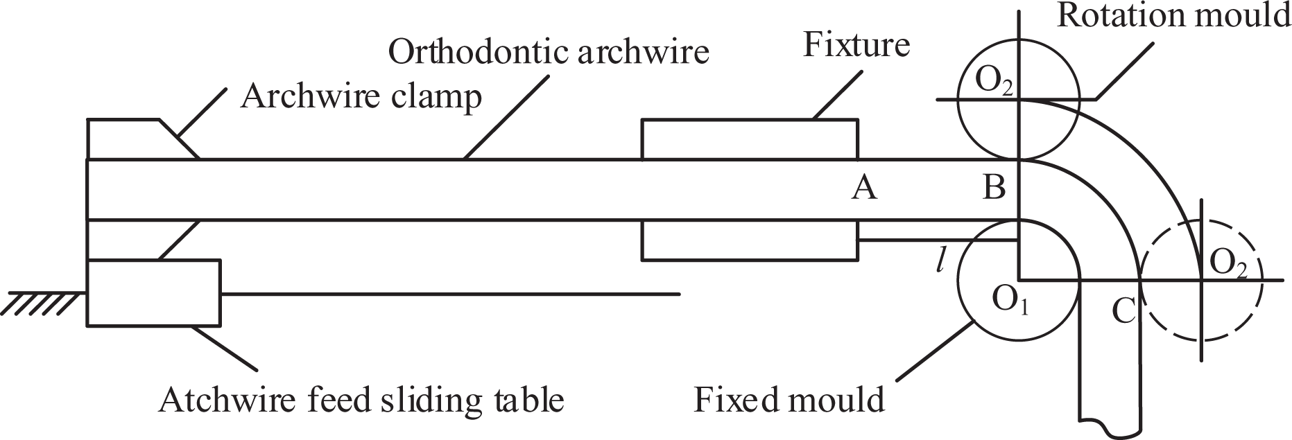
In this study, the way of rotary bending is adopted to bend the orthodontic archwires. The simplified model of the wire feeding mechanism and the wire bending mechanism is shown in Figure 1. The left end of the orthodontic archwire is clamped by the archwire clamp. The archwire is fed by feed platform. The right end of the archwire, extending from the fixture, passes between the rotation mold and the fixed mold. In the bending process, the archwire is clamped by archwire clamp in order to prevent its rotation and movement. Archwire is supported by the fixture to avoid the large deformation of the cantilever end. The rotation mold drives the orthodontic archwire to rotate around the center of the fixed mold to a certain angle. After the archwire is unloaded by the way of counterclockwise rotation, springback of the orthodontic archwire is generated due to elastic deformation. The remaining angle after springback is the formed angle.
Orthodontic archwire bending process.
Because the slip warping phenomenon exists in the process of orthodontic archwire bending, the simplified model of archwire bending process is shown in Figure 1. Based on the classic plastic forming theory, as shown in Figure 2, the process of archwire bending consists of parts BC and AB. The slip warping phenomenon is generated on AB part in the initial phase of the rotation mold, rotating clockwise around the gyration center of the fixed mold. At this period, the loading torque is small. The bending angle and the springback angle increase with bending moment. The elastic deformation occurs more often than that of plastic deformation, and the AB part is in an elastic deformation state in this stage. When the rotation mold rotates over a certain angle, the warping angle θB will stop changing, archwire will stop slipping, and the bending angle will stop changing with the bending moment. The plastic deformation occurs more often than that of elastic deformation, and the BC part is in a plastic deformation state in this stage.

Simplified model of archwire bending process.
The bending deformation of orthodontic archwires is affected by geometry, material, and boundary conditions. In order to simplify the analysis process, the following basic assumptions were adopted: The orthodontic archwire is an ideal elastic–plastic deformation material with the isotropy of elastic–plastic deformation. In the archwire bending process, there is no gap between the fixture and the archwire. The distance between the rotation mold and the fixed mold is equal to the side length of the archwire. The rotation mold and the fixed mold are rigid bodies and they are always in contact with the archwire. In the archwire bending process, the cross section of the archwire always stays in a plane. The cross section is perpendicular to the axis of the deformed archwire. In the archwire bending process, there is no shear stress between the longitudinal fiber layers of the archwire. In the archwire bending process, the pure bending is generated on the archwire. The outer tensile portion and the inner compression portion of the neutral layer have the same work-hardening mechanism and their plastic deformation volume remains constant.
Curvature radius of the stress–strain neutral layer considering slip warping phenomenon
In the process of archwire bending, the archwire is driven by the rotation mold to rotate around the fixed mold, the elastic deformation generated on the archwire first, and plastic deformation later on. The ratio of the distance between the geometric center of the archwire and the center of the archwire bending (1.2–1.3 mm) to the archwire thickness (0.4–0.6 mm) is between 2 and 4. Hence, the deformation of the archwire is large curvature deformation. Due to the deformation of the AB part is elastic deformation, the warping phenomenon is generated because of the slippage. In the bending process, the bending center and bending radius of the archwire keep changing; therefore, the influence of warping on springback also needs to be considered besides considering the neutral layer movement.
Some theoretical contributions on springback without considering the slip warping phenomenon had been developed in the past few years. Some of the theoretical expressions can be used in this study. In the reference literature, 24 the springback of the archwire of the elastic bending stage and the plastic bending stage was analyzed. And some conclusions were concluded, as follows.
According to Hooke’s law, the stress of the fiber layer with the removal of the load is as follows

where ρ is the curvature radius of the stress–strain neutral layer before the removal of the load, y is the distance from any l1 length fiber layer to the neutral layer, and ρ′ is the curvature radius of stress–strain neutral layer after the removal of the load.
The unloading bending moment MU is as follows

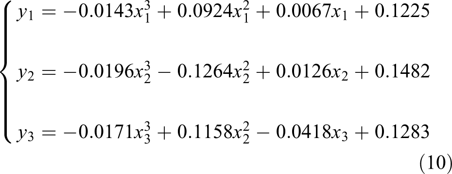
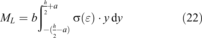
In the loading procedure, on the basis of material stretching tests, the stress–strain relationship of orthodontic archwire can be obtained using the polynomial fitting method. Therefore, the loading bending moment is as follows

where
Orthodontic archwire is in a free state after the removal of the load. That is, orthodontic archwire is in a state without bending moment. Therefore

That is

In the bending process, according to the fixed length principle of the stress–strain neutral layer, the following holds

where
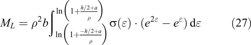
The springback angle and the formed angle in the plastic bending stage can be calculated by the synthesis of equations (1) to (6). The key to the solution is the calculation of the curvature radius, the unloading bending moment, and the loading bending moment of the stress–strain neutral layer.
Analysis of inner bending radius of archwire after plastic deformation considering the slip warping phenomenon
According to the basic assumption (1), in the elastic deformation stage, the deformation can be recovered after being unloaded. Therefore, the analysis of the changes of bending center and bending radius is not required. We just need to calculate the bending radius after plastic deformation. When archwire is in plastic deformation stage, AB part will produce maximum deflection after deforming to AB′.

Analysis of the bending radius of the archwire.
The plastic deformation of the archwire does not occur at the B point but occurs at the B′ point Δl from B point because of the relative sliding between the archwire, the fixed mold, and the rotation mold. The bending center of the archwire is no longer the center of the fixed mold but the intersection O1′ of the vertical line of a tangent passing through the B′ point and a vertical line of a tangent passing through the C point. As shown in Figure 4, the radius of bending gyration is no longer equal to a half of the sum of R1 , the radius of the fixed mold, and the thickness of the archwire but the sum of inner gyration radius R 1′ and half of the thickness of the archwire. For convenience calculation, the value of R 1′ can be obtained by R 1 according to the principle of similar triangle when the tangent of the C point on the plastic deformation part is vertical.
R1
is perpendicular to BB′. At the same time, R1
is perpendicular to O1O1′, then θB is an opposite vertical angle. Hence, ∠MBB′ is similar to

In the reference literature, 24 according to the integral method of bending deformation of the beam, the bending angle and the springback angle can be obtained by the following formula

In equation (7),


Similar triangles of archwire bending radius.
The procedure for obtaining the arc length of
Warping curve fitting point (mm).


Fitting curve of warping section AB′.
Analysis of bending and gyration radius of archwire after plastic deformation
In the bending process, the curvature radius of the stress–strain neutral layer is not equal to the sum of the radius of the fixed mold and the half thickness of orthodontic archwire. However, the curvature radius of the stress–strain neutral layer is less than this sum due to the stress–strain neutral layer moves a certain distance toward the bending center. According to curved beam theory, we assume that the orthodontic archwire is bent by a certain angle, and the calculation principle of the curvature radius of the stress–strain neutral layer is shown in Figure 6.
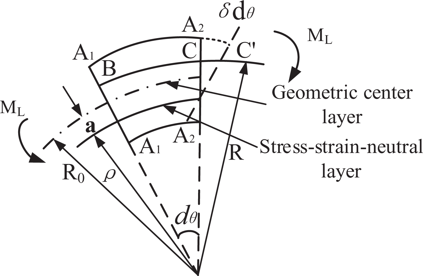
Deformation analysis of the curvature radius of the neutral layer of orthodontic archwire.
For the study of a fraction of orthodontic archwire dθ, the arc length of the fibrous layer

At this stage, we assumed that the dθ section corresponding to

Dependent variable

According to the generalized Hooke law, the stress is as follows

The tensile force acting on the dθ section is as follows

According to the basic assumption (5), the pure bending is generated on the archwire. Therefore, a pulling force acting on a minor segment F = 0, that is

Because of

Let

The inner bending radius of archwire after plastic deformation considering the slip warping phenomenon was analyzed in the last section. And
Calculation of curvature radius of neutral layer of stainless steel archwire considering the slip warping phenomenon
In the bending process, the cross section of the stainless steel archwire is shown in Figure 7, where b is the width of the stainless steel archwire and h is the height of the archwire. a is the distance between the intermediate layer and the neutral layer. y is the distance between any fiber layer and the neutral layer.

Stainless steel archwire bending section.
Differential area expression of any micro-deformed fiber layer with a distance of y from the neutral layer can be obtained from Figure 8, as follows

The rotation angle of the rotating mold in contact with the archwire.
Equation (19) is substituted into equation (18), and then the curvature radius of the neutral layer of stainless steel archwire is as follows

where R1′ is the bending radius of the orthodontic archwire. R1′ is not equal to the radius of the fixed mold,
Calculation of loading and unloading moment of stainless steel archwire considering the slip warping phenomenon
Equation (20) is substituted into equation (2), and then the unloading moment of stainless steel archwire in the stage of restoring natural form considering the slip warping phenomenon is as follows

Similarly, equation (19) is substituted into equation (3), and then the loading bending moment of stainless steel orthodontic archwire considering the slip warping phenomenon is as follows
where a is as follows

Under the condition of considering the real stress–strain relationship, the calculation of the real strain is as follows

where ε = y/ρ is the engineering strain of longitudinal fiber layers in archwire bending process.
The following results can be obtained according to the basic assumption (5), the volume of the archwire is constant before and after bending according to the basis of equation (24), and the engineering strain of longitudinal fiber layers considering the slip warping phenomenon in archwire bending process is as follows


On the basis of the synthesis of equations (22) to (26), the loading moment of stainless steel orthodontic archwire considering the slip warping phenomenon is as follows
where
The establishment of mathematical model of springback of stainless steel orthodontic archwire considering the slip warping phenomenon
On the basis of the synthesis of equations (4), (6), (20), (21), and (27), the calculation equation for the springback angle of the BC part of the stainless steel orthodontic archwire is as follows
After springback, the formed angle is expressed as follows
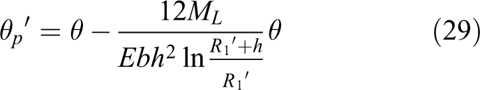
Hence, the mathematical model of springback of stainless steel archwire considering the slip warping phenomenon was established as follows

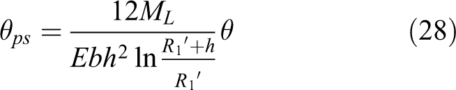
where K is the correction factor of processing from elastic deformation stage to plastic deformation stage. The process of deforming from elastic stage to plastic stage is continuing. When the maximum loading moment is ML , K can be calculated under the condition of the formed angle θ′ and bending angle θ of elastic bending which are equal to that of plastic bending. When the formed angle θ′ is equal to the bending angle θ, the rest parameters but K in equation (30) are already known. K can be calculated by substituting these known parameters into equation (30). In equation (30), θib is the boundary value of the bending angle. The elastic deformation is generated on the archwire when the bending angle θ is less than θib. On the other side, The plastic deformation is generated on the archwire when the bending angle θ is larger than θib. l is the length of the neutral layer and the n is the arm of the force. Substituting the maximum loading moment ML into equation (30), the formed angle θ′ can be calculated from equation (30).
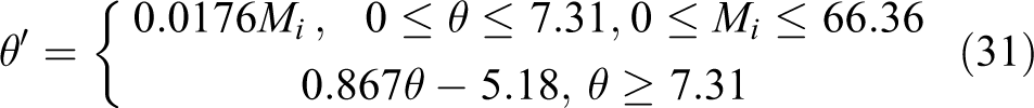
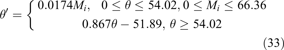
Based on the theoretical deduction above, the mathematical model of springback of stainless steel orthodontic archwire was established. According to the performance index of stainless steel orthodontic archwire in this experiment, E, the elastic modulus, is 209 GPa. The size of the stainless steel orthodontic archwire is 0.4064 mm × 0.4064 mm. According to (equation (30)) the mathematical model of springback of stainless steel orthodontic archwire, the final mathematical model of springback of stainless steel orthodontic archwire in this experiment was established as follows
The experiment and the compensation of the springback mechanism model considering the slip warping phenomenon of the orthodontic archwire
The deviation of the theoretical model in the experiment is unavoidable because of the basic assumptions of the mathematical model of the springback mechanism and the irresistible factors in the experiment process. Therefore, this study compensated and demonstrated the correctness of the springback mechanism model through theoretical analysis and experimental verification.
The compensation of the springback mechanism model of the orthodontic archwire
In order to meet the needs of different kinds of orthodontic archwires, the clearance between the fixed mold and the rotation mold of the bend gripper is greater than that of the length of the cross section of the orthodontic archwire, which is the reason why the archwire does not bend at the initial stage of the rotation mold rotated around the fixed mold. It was assumed that the rotation mold is in contact with the archwire after the rotation of α angle. The extraction process of α is shown in Figure 8. In Figure 8, the radii of the rotation mold and the fixed mold R are 1 mm. The height of the archwire h is 0.4 mm. The center distance c between the rotation mold and the fixed mold is 3.5 mm. α can be solved by the following formula
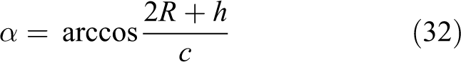
According to the calculations result, α is about 46.71°. The springback mechanism model of stainless steel archwire considering the slip warping between the rotation mold and the fixed mold was established as follows
Experiment of the springback mechanism model considering the slip warping phenomenon of the orthodontic archwire
The orthodontic archwire bending experiment was carried out by an orthodontic archwire bending robot, and the formed angle was measured after being unloaded. The 0.4064 mm × 0.4064 mm stainless steel archwires were used in this experiment. The formed angles were measured four times and the average of experimental formed angles was obtained. The measurement of the bending angle of the archwire after being unloaded is shown in Figure 9. The bending angle of the archwire after being unloaded is measured by the OLYMPUS metallographic microscope with the distance of 25mm and the minimum scale is 0.01 um. The measurement of the bending angle of the archwire is shown in Figure 10.

Measurement of the angle of the bend forming of the archwire.

Measurement of the bending angle of the archwire after being unloaded.
As shown in Figure 11, the proposed robotic orthodontic archwire bending system mainly consists of three parts: the control software, the control unit, and the robot body.

Robotic orthodontic archwire bending system.
The control software is based on LabVIEW software and mainly includes two modules: upper and lower jaw parameter setting module and orthodontic arch bending control module. The upper and lower jaw parameter setting module is mainly used to read the information of the arch curve, insert special arch curve, and adjust the angle and position of the curve line. Orthodontic archwire bending control module is mainly used to control the individual movements of the robot joints, carry out robotic archwire bending program, and interrupt and mediate the operation of the robot. The core of the control unit is a PMAC card. In this system, the pulse signal is amplified by the stepping motor driver to control the coordinated movement of the joints of the robot.
The structure diagram of the robot body is shown in Figure 12, and the movement of the X-direction is realized by the ball screw moving platform with effective stroke of 200 and 10 mm guide. The freedoms of Y- and Z-directions are used to realize the position adjustment between the archwire bending mechanism and the orthodontic archwire. Two ball screw moving platforms with effective stroke of 100 and 10 mm guide are used in this part. The archwire rotating mechanism is connected with the X ball screw moving platform through the L-shaped connecting board. The archwire rotating mechanism is mainly composed of a 42-type step motor and a three-claw chuck. The archwire bending mechanism is composed of the 42-type step motor with a planetary gear reducer, a three-claw chuck, and a bending gripper. The body of orthodontic archwire bending robot is shown in Figure 13. And the structure of the bending gripper is shown in Figure 14.

Structure of orthodontic archwire bending robot.

Body of orthodontic archwire bending robot.

Bending gripper relationship with relative location of orthodontic archwire.
Some preparations are needed before the orthodontic archwire bending experiment. The X ball screw moving platform should be moved to the end side of the step motor. The archwire needs to go through the gap between the rotation mold and the fixed mold. And the other side of the archwire should be fixed by the three-claw chuck of the archwire rotating mechanism. A proper position of the archwire and the bending gripper can be found by adjusting the Y and Z ball screw moving platforms.
In the orthodontic archwire bending experiment, the orthodontic archwire bending process is mainly divided into two parts: the first sequence curve bending and the second sequence curve bending. The first sequence curves are usually on the horizontal plane. And the second sequence curves are on other planes. In the bending process of the first sequence curve, the archwire is fed by the movement of the X ball screw moving platform in X-direction. The movement of the X ball screw moving platform in X-direction should be stopped after a feeding. At this time, the bending gripper is driven by the rotation of the step motor of the archwire bending mechanism and rotates in clockwise. After that, the step motor of the archwire bending mechanism rotates in the negative direction to reset the position of the bending gripper. And the X ball screw moving platform in X-direction fed again. The bending of the first sequence curve can be realized by repeating these movements.
When a second sequence curve needed to be bent, the bending platform needed to change. After the first sequence curve bending, the archwire should be fed by the X ball screw moving platform to realize the bending of the second sequence curve. And the step motor of the archwire rotating mechanism rotates in clockwise or anticlockwise direction. The rotation direction depends on the shape of the archwire curve. The archwire rotates with the rotation of the step motor. At this time, the bending gripper is driven by the rotation of the step motor of the archwire bending mechanism and rotates in clockwise. After that, the step motor of the archwire bending mechanism rotates in the negative direction to reset the position of the bending gripper. The bending of the second sequence curve can be realized by these movements. And an archwire can be bent by the combination of these movements of the orthodontic archwire bending robot. The bending angle and the formed angle of the archwire in this experiment are shown in Table 2. The bending angle and formed angle of the archwire in the model of bending springback are shown in Table. 2.
The formed angle and the bending angle of the orthodontic archwire in the experiment and the model of bending springback.
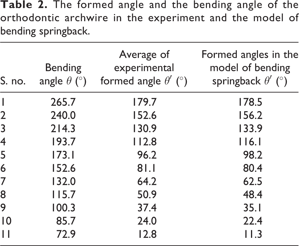
Each bending angle in Table 2 is substituted into equation (31), and then the formed angles of the archwire in the model of bending springback are as shown in the last column of Table 2. And four experiments were carried out with the same bending angle θ of each line in Table 2. The average of experimental formed angles in the third column of Table 2 is the average values of four experiments.
The experimental data and theoretical data of the bending of the orthodontic archwire were compared and analyzed, as shown in Figure 15. It can be seen from Figure 15 that the experimental data of the bending springback of the archwire were approximately linear, and the formed angle increases gradually with the bending angle and the unloading formed angle. The springback mechanism model of the orthodontic archwire is linear and has the same slope with experimental data. The theoretical model data were coincided with the experimental data, which proves that the springback mechanism model considering the slip warping phenomenon of the orthodontic archwire meets the requirements.

Comparison of the experimental result and theory value.
Bending experiment for stainless steel orthodontic archwire
Bending experiment of the stainless steel archwire
To make our experiments represent for majority of humans, dentition and bracket model of the patient are shown in Figure 16. In this experiment, the robotic system was calibrated to reduce the experimental error. The robotic system is introduced in the third chapter. The 0.4064 mm × 0.4064 mm stainless steel archwires were used in this experiment. Respectively, l1 and w1 are the height and width of the canine teeth offset, l2 and w2 are the height and width of the molar offset, and l3 and w3 are the height and width of the dental arch. And l1 , l2 , l3 , w1 , w2 , and w3 are the important parameters usually used to design the orthodontic archwire. And they are also the standards for measuring the bending accuracy of the archwire in this experimental. The ideal dental parameters of the patient are shown in Figure 17. The ideal parameters are used to compare with the experimental results in the discussion part. The experimental bending process is shown in Figure 18.

Dentition and bracket model of the patient.

Ideal dental arch parameters of the patient.

Experimental process.
Experimental results for stainless steel orthodontic archwire bending
The bending experiment of stainless steel orthodontic archwire was conducted by the experimental robotic orthodontic archwire bending system. Experimental results for stainless steel orthodontic archwire without considering the slip warping phenomenon are shown in Figure 19. Experimental results for stainless steel orthodontic archwire considering slip warping phenomenon are shown in Figure 20.

Experimental results for stainless steel orthodontic archwire without considering the slip warping phenomenon.

Experimental results for stainless steel orthodontic archwire considering slip warping phenomenon.
In the robotic archwire bending experiment, the orthodontic archwire is bent by the bending gripper of the orthodontic archwire bending robot. The rotated angle of the bending gripper which is called the bending angle can affect the shaped accuracy. In this study, the springback mechanism model of stainless steel archwire considering the slip warping phenomenon is built to calculate the proper bending angle. The shape of the experimental archwire in Figure 20 agrees with the ideal archwire shape in Figure 17. As shown in Table 3, while not considering slip warping phenomenon, the error ratios for the height of the canine teeth offset, the width of the canine teeth offset, the height of the molar offset, the width of the molar offset, the height of the dental arch, and the width of the dental arch were between 1.1% and 7.9%. As shown in Table 3, while considering slip warping phenomenon, the error ratios for the height of the canine teeth offset, the width of the canine teeth offset, the height of the molar offset, the width of the molar offset, the height of the dental arch, and the width of the dental arch were between 1.1% and 3.0%. Hence, the experimental results for rectangular orthodontic archwire considering slip warping phenomenon are superior to those without considering slip warping phenomenon.
Error ratio comparison between considering slip warping phenomenon and not considering slip warping phenomenon.

Conclusion
The process of the springback of the stainless steel archwire was analyzed based on the archwire bending principle. The influence of the slip warping phenomenon of the archwire between the fixed mold and the rotation mold was considered in the analysis of the springback mechanism. The bending process of archwire was divided into two stages: elastic deformation and plastic deformation, based on the changes of the bending radius in the bending process. A springback mechanism model of the orthodontic archwire considering the slip warping phenomenon was established. The springback mechanism model of the orthodontic archwire was analyzed and compensated based on the characteristics of the robot structure. The data of the maxillary tooth of one patient were collected as theoretical value, and the bending experiment for stainless steel archwire was carried out. The experimental results show that considering the influence of the slip warping phenomenon can improve the bending accuracy.
Footnotes
Declaration of conflicting interests
The author(s) declared no potential conflicts of interest with respect to the research, authorship, and/or publication of this article.
Funding
The author(s) disclosed receipt of the following financial support for the research, authorship, and/or publication of this article: This research was supported by the University Nursing Program for Young Scholars with Creative Talents in Heilongjiang Province (Grant No. UNPYSCT-2017082), China Postdoctoral Science Foundation Funded Project (Grant No. 2016M591538), Heilongjiang Postdoctoral Science Foundation Special Funded Project (LBH-TZ1705), Heilongjiang Postdoctoral Science Foundation Funded Project (Grant No. LBH-Z16091), and Science Funds for the Young Innovative Talents of HUST (Grant No. 201509).