
Abstract
This study introduces a two-wheeled self-balancing mobile robot based on a control moment gyroscope module. Two-wheeled mobile robots are able to achieve better mobility and rotation in small spaces and to move faster than legged robots such as humanoid type robots. For this reason, the two-wheeled mobile robot is generally used as a mobile robot platform. However, to maintain its balance, the two-wheeled robot needs to use movements of its two wheels. When an unexpected disturbance affects the robot, the robot maintains its balance with movements of the wheels and tilting of the body. If the disturbance exceeds the response capability of the robot, the robot will lose its stability. At the same time, the safety of the robot may be put at risk by movements to maintain balance. To address these issues, a robot was designed with a control moment gyroscope module to improve balance while minimizing movement. When a disturbance is applied to the robot, the disturbance is estimated by a disturbance observer and the control moment gyroscope controller compensates the disturbance. Using the control moment gyroscope module, the robot can maintain balance with just small movements of its wheels. Improved performance and stability were verified with experiments and simulations.
Introduction
Wheeled mobile robots have a significant advantage over humanoid type robots, in that they are faster and can more easily change direction while moving, and this makes them very useful for a number of applications. Among wheeled robots, two self-balancing robots, the Segway and Ninebot, have become popular and are used for commuting or as patrol transporters. 1,2 In addition, self-balancing wheeled robots such as Anybots QB are currently used as a service robot platform. 3,4 Due to their increasing popularity, advanced self-balancing robots are currently being developed as well. The Golem Krang was developed at the Georgia Institute of Technology. Its base is similar to a normal two-wheeled self-balancing robot, but it has anthropomorphic arms. 5 The two wheels of the robot are used to balance the body and the robotic arm, which is fixed to the upper body, is designed to perform tasks such as removing obstacles. The Ballbot was developed at Carnegie Mellon University. This robot system is designed to balance on a sphere, which makes it particularly easy to switch orientation and move in any direction. 6 In addition, KAIST has developed a two-wheeled self-balancing robot that has an upper body with five degrees-of-freedom. By using its upper body, the robot maintains a dynamic balance based on the zero-moment point. 7
As different types of self-balancing robots become more frequently used in various fields and different environments, it is increasingly important to prevent accidents. It is well-known that the owner of Segway Inc., Jimi Heselden, died in an accidental fall while riding a Segway in 2010. In similar accidents, when the self-balancing robot encounters an unexpected disturbance, it can lose its stability. Even though more robust control algorithms for the self-balancing robot have been developed for stability, 8,9 they do not perfectly guarantee safety. For example, the robust algorithm can guarantee better stability against disturbances. But, because of the characteristics of the self-balancing robot, the robot has to move its wheels and tilt its body to keep balance. It cannot stay in one place while responding to an external force. 10 It is obvious that the larger the disturbance, the more the robot moves. Even when the robot is located in front of a cliff or a human, if a disturbance is applied to the robot, the robot has to move itself to keep balance, and in that case, there is a risk that the robot will fall or hit the human. In other words, even when the robot maintains its stability, it can become unsafe. 11,12 And For this reason, it is important that the control algorithm not only keeps the self-balancing robot stable but also ensures that it maintains its position Thus, it has to be equipped with additional hardware to guarantee both stability and safety at the same time.
Representative self-balancing robots which have additional equipment for balancing include the Murata Boy developed by Murata of Japan 13 and the C1 developed by Lit Motors, USA. 14,15 The Murata Boy is a robot that has a flywheel mounted on the body riding a bicycle. The flywheel generates torque around the roll axis and this enables the robot to control its posture along the roll axis. The C1 is a motorcycle having an electrically controlled control moment gyroscope (CMG). The CMG generates torque via a rotating flywheel and gimbal and is mainly used for attitude control of satellites and for roll control of large ships, because it can generate higher torque more precisely than a flywheel. Using the CMG prevents the C1 from falling down in accident situations. In addition, the CMG makes it easier to drive at low speed and maintain balance while stopping because it controls balance along the roll axis. However, because of the CMGs characteristics, the CMG cannot be used for continuous or constant disturbances. 16
This article introduces the development of a two-wheeled self-balancing robot, called the Kookmin University segWAY (KUWAY), which employs CMG to generate torque around the pitch (left–right) axis. The KUWAY is shown in Figure 1. Even though most systems having CMG use it to generate torque around the roll axis, in the KUWAY, the CMG generates torque around the pitch axis. As a result, the KUWAY can maintain its balance against a disturbance while using minimized movement. That is, it guarantees both stability and safety.

KUWAY. KUWAY: Kookmin University segWAY.
Hardware
The KUWAY introduced in this article is a two-wheeled self-balancing robot with CMG. It is comprised of two main parts, a self-balancing robot and a CMG module, as shown in Figure 2. The main controller (TMS320F2808 developed by Texas Instrument) controls the self-balancing algorithm of the robot and the CMG module. A detailed explanation for each part is provided below. And the communication part act that the KUWAY communicates with laptop using Bluetooth to observe the status of KUWAY in Figure 2. This allows the state of the KUWAY to be monitored in real time while the robot is operating.

A block diagram of KUWAY. KUWAY: Kookmin University segWAY.
Self-balancing robot
The self-balancing robot part is similar to other typical two-wheeled self-balancing robots, such as the Segway. Its role is to maintain balance using movement of the wheels and body. It is driven by two actuators consisting of a DC motor and a pulley/belt mechanism. The DC motors are Ampflow DC motors (A28-150) operated at 24 V and have 3 HP (2.2 kW) power. The motor has a maximum speed of 6100 rpm and a maximum torque of 13.9 Nm.
To increase the torque of the actuator, a pulley/belt mechanism was adopted. The reduction ratio was set to about 10:1. Because of the limited size of the pulley, two pulley/belt mechanisms were serially connected. Thus, the reduction ratio of the single pulley/belt mechanism was selected to be 3.14:1 (44:14) and the final reduction ratio became 9.88:1 (442:142). Both motors have a rotary encoder of 1000 ppr to measure angle.
In order to measure the tilt angle and angular velocity of the robot, an inertia measurement unit (IMU) was developed. The IMU consists of an inclinometer (DAS, M1) and a gyro sensor (Silicon Sensing Systems, CRS 03-02). Even though the inclinometer can accurately measure the tilt angle of the body, it cannot measure the correct angle during fast rotation because of centrifugal force. On the other hand, the gyro sensor used to measure the angular velocity of the body can estimate the angle of the body by integrating angular velocity. However, drift may occur due to the accumulation of errors in the steady state.
In order to compensate the limitations of the two sensors, a complementary filter was applied as shown in Figure 3. The complementary filter has a low-pass filter for the inclinometer and a high-pass filter for the gyro sensor. The cut-off frequencies of both filters were determined experimentally. In this article, the cut-off frequency is decided to 0.2 Hz.

A block diagram of the complementary filter.
CMG module
The CMG module used in the KUWAY is shown in Figure 4. It was placed on the self-balancing robot as shown in Figure 1. The module consists of two CMGs and each CMG has two actuators. One actuator rotates the flywheel and the other rotates the gimbal where the flywheel is contained. The CMG generates torque in a direction perpendicular to the rotational axes of the flywheel and gimbal. The magnitude of the torque is the product of the angular velocity of the gimbal and the momentum of the flywheel. In order to generate enough torque, it is necessary to have a bigger moment of inertia and/or a faster flywheel speed. To ensure that the torque of the CMG is accurate, the two flywheels need to rotate at a constant speed. For this reason, each flywheel was equipped with a 270W DC motor (RS-775wc, MABUCHI) and a rotary encoder to control rotation. The gimbal motor used in the CMG does not need high speed, just sufficient torque, so the DYNAMIXEL MX-106T from Robotis was selected.
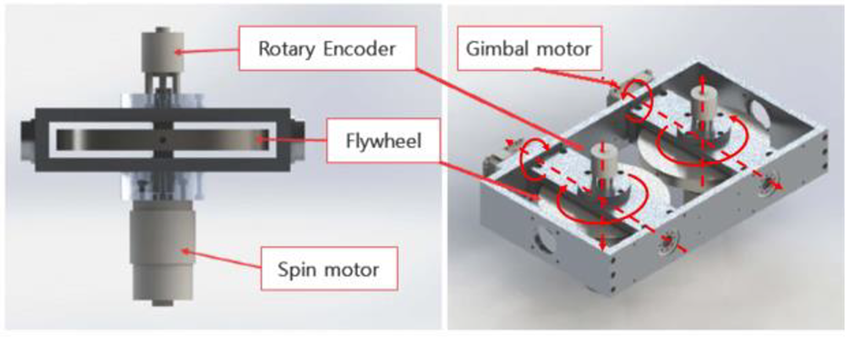
The CMG. CMG: control moment gyroscope.
Modeling of KUWAY
Modeling of self-balancing robot
When the two-wheeled self-balancing robot encounters a disturbance, its stability is mainly affected by disturbances which are applied in the back and forth directions. Therefore, the stability and the safety of the KUWAY were dominantly handled in the sagittal plane. Figure 5 shows a free body diagram of the self-balancing robot of the KUWAY in the sagittal plane. Equations (1) and (2) are the equations of motion applied with the motor dynamics
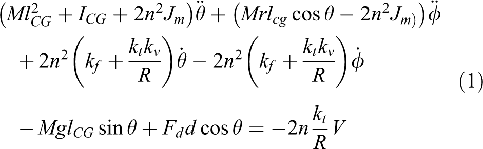

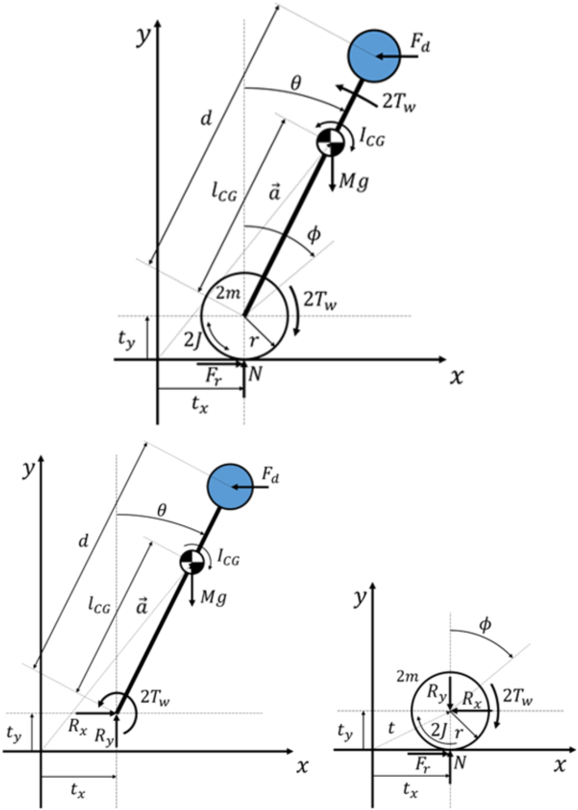
A free body diagram of the self-balancing robot of the KUWAY in the sagittal plane. KUWAY: Kookmin University segWAY.
where θ is the tilit angle of the body, ϕ is the rotational angle of the wheel, and
The parameters of the KUWAY.

KUWAY: Kookmin University segWAY.
Modeling of the CMG
In the KUWAY, the CMG generates torque on the basis of precessional motion. That is, when the flywheel rotates (along the z′-axis in Figure 6) and the gimbal containing the flywheel rotates along a direction perpendicular to the rotational axis of the flywheel (y-axis), the torque is generated along the direction of the cross product of both vectors (x′-axis). Figure 6 shows a free body diagram of a single CMG. If the angular velocity of the gimbal is denoted as

where

Here,
Because of the angle of the gimbal (

Free body diagram of single CMG. CMG: control moment gyroscope.
To solve this, the CMG module of the KUWAY was designed with two CMGs as shown in Figure 7. If the torque generated by the first CMG is denoted as 

Free body diagram of two CMGs. CMG: control moment gyroscopes.
If both flywheels are controlled to rotate with the same magnitude and in opposite direction (

If the variation of the gimbal is small around zero, the torque generated by the CMG module is

Control of the KUWAY
Figure 8 shows the overall control scheme for the KUWAY. It consists of the balancing controller for the two-wheeled self-balancing robot and the CMG controller reducing the effect of disturbances in order to keep a position. The details of each will be explained.

Control Scheme for the KUWAY. KUWAY: Kookmin University segWAY.
Balancing controller
In order to get the state space equation, the equations of motion for the self-balancing robot, equations (1) and (2), are linearized around


That is

where

where
If the desired trajectory

Then, the error dynamics without the disturbance are expressed by equations (10) and (11) as

where

where Q and R are properly selected as a result of experiment. Therefore, the control law to track the desired trajectory is

where K is a control gain. That is

Disturbance observer
Using the controller discussed in the previous section, the normal two-wheeled self-balancing robot was able to maintain its balance even against large disturbances. In order to maintain stability against a disturbance, the robot moved its wheels and tilted its body. However, in terms of safety, it is sometimes necessary for the robot to stay in its position or minimize movement when a disturbance occurs. To accomplish this, the KUWAY was equipped with the CMG module that reduces the effect of the disturbance. Since there is no sensor to measure the disturbance, the disturbance is estimated by the disturbance observer. Equation (10) can be expressed as

The reduced order observer equations are obtained as

Then

where
CMG controller
When a disturbance occurs, the CMG module of the KUWAY generates a reaction torque that corresponds to the disturbance. The CMG module of the KUWAY operates the gimbal motor using the PID controller, based on feedback regarding the disturbance, as measured by the observer. Since the goal is to eliminate the effects of that disturbance, the desired disturbance
Experiment
Experiment operating the balancing controller
The performance of the balancing controller was verified by the experiment. The control gain was

when

The experimental result for the balancing controller.
Verification of the disturbance observer
Next, the designed disturbance observer was verified by experiment. The actual disturbance was measured using a push–pull gauge to determine the vertical force. Since it is difficult to measure any disturbance when the KUWAY is being controlled, the experiment was conducted without the balancing controller. The wheels were locked and the body was inclined as shown in the left panel of Figure 10. The body was supported by the push–pull gauge to preserve the inclination. That is, the disturbance was generated and measured using the push–pull gauge. According to the inclination, the disturbance can be changed. The right side of Figure 10 shows the experimental results, where the red line is the real disturbance measured by the push–pull gauge and the black line is the estimated value. Both graphs are very similar to each other. Therefore, the designed disturbance observer was verified to work well.

Comparison of the estimated observed disturbance and the measured real disturbance.
Experiment for the CMG module
The performance of the CMG module of the KUWAY was experimentally measured to verify the amount of torque generated. In the experiment, the moment of inertia of the flywheel

The real torque generated by the CMG module was measured using the push–pull gauge. In the experiment, the wheels were fixed to the body, and the balancing controller was not used to balance the body. The generated torque was converted to the force for the measurement using the push–pull gauge. As shown in Figure 11, the moment arm was set to l (

Experiment using the CMG module. CMG: control moment gyroscope.
In addition, another experiment was conducted. In the experiment, the wheels of the KUWAY were locked so that the KUWAY became an inverted pendulum. Then, using only the CMG module, the KUWAY was controlled to maintain balance. The controller was simply designed with a conventional PID controller to regulate the tilt angle of the body. The experimental result is shown in Figure 12. The KUWAY was able to maintain balance with a small variation in tilt angle from −0.02 rad (−1.1°) to 0.03 rad (1.7°).
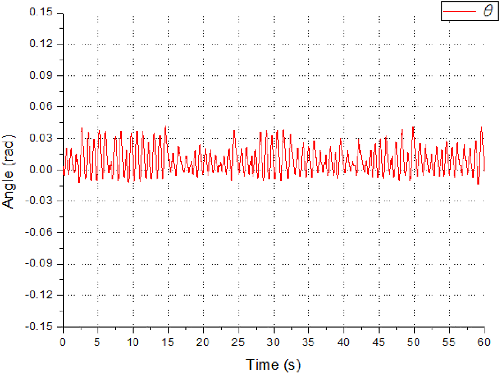
Self-balancing experiment using only the CMG module. CMG: control moment gyroscope.
However, it sometimes failed to control the body. In order to generate torque, the gimbal motor has to rotate. Even if the tiny biased disturbance is applied to the robot, the gimbal motor rotates to the specific direction. At last, it will reach to singularity, where the two rotation axes of the flywheels are on a straight line. At this moment, the control fails because no torque is generated by equation (5). For this reason, the CMG module cannot be used continuously but should only be operated for short periods by the time the rotation axes of the flywheels are on the generated torque axes.
Experiment for disturbance
In order to observe the effect of the CMG module, two experiments were carried out where the KUWAY maintained balance against a disturbance. In the first experiment, the KUWAY was balanced with just the balancing controller, and in the second experiment, both controllers, the balancing controller and the CMG controller, were applied. Then, the experimental results were compared. The experimental setup is shown in Figure 13. A dead weight of 10 kg was swung from a 25° angle with a moment arm of 0.5 m so that it would hit the robot on the front side.

Disturbance experiment.
Figure 14 shows the result of the first experiment, confirming that the KUWAY maintained its balance. In this graph, θ means angle of the body,

Results for all aspects in the balancing experiment measuring the response to an inflicted disturbance, using only the balancing controller.
Body slope during disturbance experiment without CMG. CMG: control moment gyroscope.
Figure 16 shows the results of the second experiment, using both the balancing and CMG controllers, with the same disturbance as before. The CMG controller reduced the disturbance while the balancing controller maintained stability. When the dead weight hit the KUWAY at around 1.5 s, the robot moved approximately 28 cm backward while the wheels rolled 1.4 rad (80.21°). Also, the maximum slope of the body was 7.5°, as shown by the red line in Figure 15. Finally, the KUWAY returned to a steady state within 5 s. Therefore, it was clearly demonstrated that the degree of movement of the robot and the angle of the body were reduced when the CMG controller was applied. The improvements were 22.2 and 40.0% in terms of the moving distance and the tilting angle, respectively, calculated with following equation

Body slope during disturbance experiment with CMG. CMG: control moment gyroscope.
In addition, two experiments were compared in terms of the torque of the motor to drive the wheel. Torque can be calculated based on the motor dynamics, as

Figure 17 shows the results of the comparison. The black line indicates that up to 50 Nm wheel motor torque was required to maintain balance when only the balancing controller was used. On the other hand, the red line indicates that the maximum torque of the wheel motor was only 35 Nm when the CMG module was used with the balancing controller. The difference is about 15 Nm, and it indicates the maximum torque generated by the CMG module in equation (20). As a result, the maximum necessary torque was reduced by 30.0% by applying the CMG module.

Comparison of the wheel motor torque needed to balance the KUWAY. KUWAY: Kookmin University segWAY.
Even though the sum of the generated torques makes no difference, there are effects to reduce a burden of the wheel motors and distribute load of the wheel motor to the CMG module. If the CMG module generates higher torque, the load on the wheel motor will be correspondingly reduced. For example, the radius of flywheel is increased for higher torque generated by CMG module.
Discussion
Even though performance was improved by applying the CMG module, the effect of disturbances was not entirely eliminated and the KUWAY was still moved by the disturbances. This is because the CMG module generated an insufficient level of torque based on its hardware specification. Through simulation, it is possible to verify the effect of an improved CMG module.
Figure 18 shows the estimated disturbance for the conditions used in the previous section, where the dead weight hit the KUWAY, based on equation (18). From the figure, the disturbance can be simplified as a constant disturbance with 220 N in magnitude and 50 ms in time duration. Based on the previous model of the KUWAY, a simulation was conducted using the simplified disturbance. In order to verify that the simplified disturbance and the simulation model were correct, the KUWAY was controlled against the disturbance in the simulation with just the balancing controller. Figure 19 shows the result, which is very similar to that in Figure 14. The KUWAY moved about 30 cm (1.5 rad in wheel rotation) backward and the maximum tilt of the body was 11.5°.

The estimated disturbance.

Results of the simulation where the KUWAY was only controlled with the balancing controller against the disturbance. KUWAY: Kookmin University segWAY.
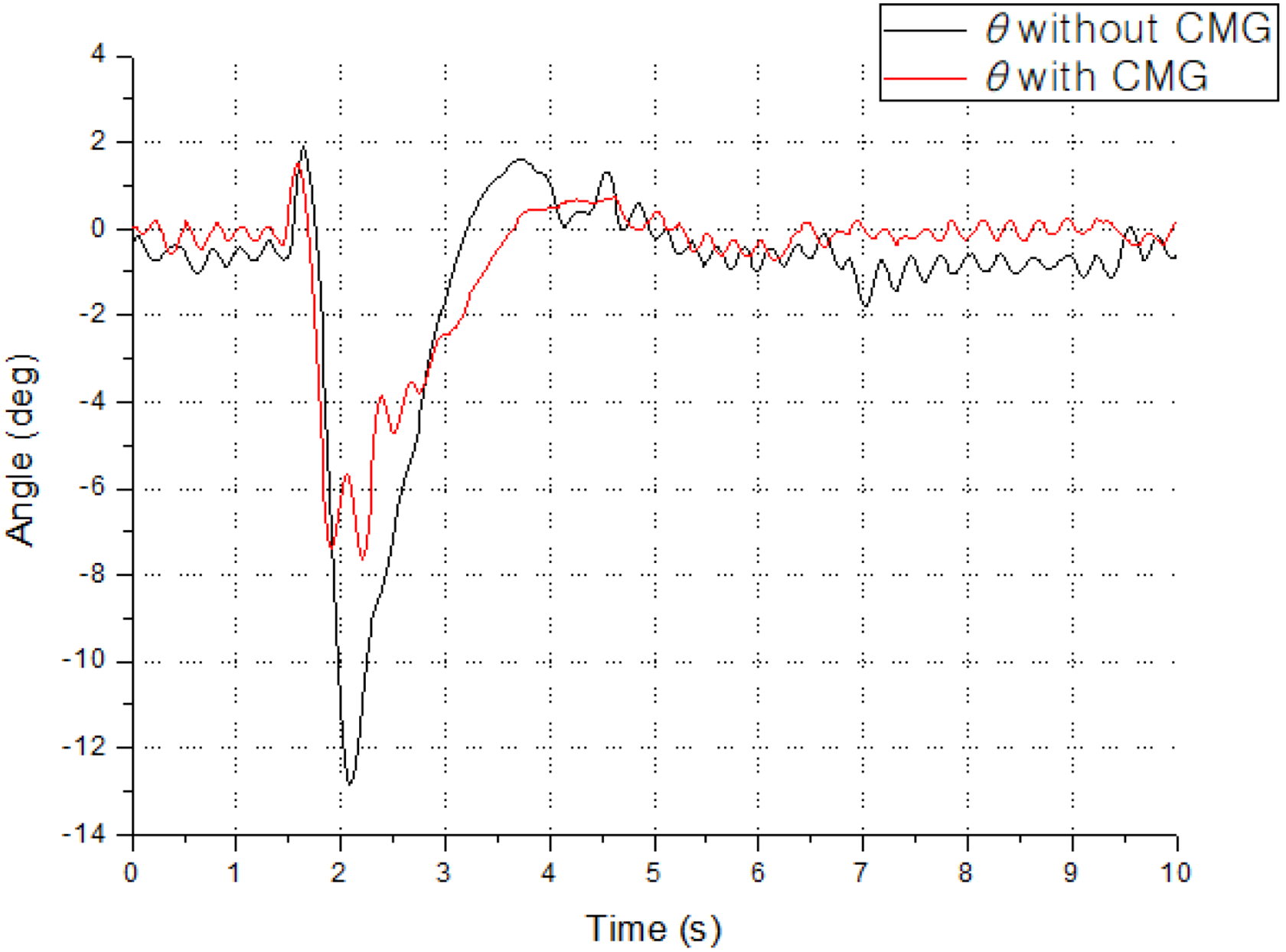
In order to verify the effect of the improved CMG module, the diameter of the flywheel was increased 1.5 times in the model, but it was rotated at the same speed. That is, the moment of inertia was increased about 5 times (

The simulation result where the KUWAY controlled with the balancing controller and the improved CMG controller against the disturbance. KUWAY: Kookmin University segWAY; CMG: control moment gyroscope.
Conclusion
Usually, a self-balancing robot has to change its position to maintain balance when an external force is applied. This is not a problem if only stability is considered. However, if the robot is in a narrow space, the movement caused by the disturbance can create a real problem. In order to solve this problem, the two-wheeled self-balancing KUWAY robot was developed, incorporating a CMG module. Through experiments, it was confirmed that the CMG module in the KUWAY generated sufficient torque to decrease the effect of the disturbance. In addition, the CMG module distributed the burden of the wheel motors. Even though the CMG module reduced the movement and the tilt of the body of the experimental robot when a disturbance was applied, the performance was not perfect. Using a simulation, it was verified that the performance was improved using a CMG module which generated higher torque. As following research, the improved CMG module will be developed and applied to experimentally demonstrate the improved performance.
Footnotes
Declaration of conflicting interests
The author(s) declared no potential conflicts of interest with respect to the research, authorship, and/or publication of this article.
Funding
The author(s) received no financial support for the research, authorship, and/or publication of this article.