
Abstract
Human activities in maintenance of industrial plants pose elevated risks as well as significant costs due to the required shutdowns of the facility. An aerial robotic system with two arms for long reach manipulation in cluttered environments is presented to alleviate these constraints. The system consists of a multirotor with a long bar extension that incorporates a lightweight dual arm in the tip. This configuration allows aerial manipulation tasks even in hard-to-reach places. The objective of this work is the development of planning strategies to move the aerial robotic system with two arms for long reach manipulation in a safe and efficient way for both navigation and manipulation tasks. The motion planning problem is addressed considering jointly the aerial platform and the dual arm in order to achieve wider operating conditions. Since there exists a strong dynamical coupling between the multirotor and the dual arm, safety in obstacle avoidance will be assured by introducing dynamics awareness in the operation of the planner. On the other hand, the limited maneuverability of the system emphasizes the importance of energy and time efficiency in the generated trajectories. Accordingly, an adapted version of the optimal Rapidly-exploring Random Tree algorithm has been employed to guarantee their optimality. The resulting motion planning strategy has been evaluated through simulation in two realistic industrial scenarios, a riveting application and a chimney repairing task. To this end, the dynamics of the aerial robotic system with two arms for long reach manipulation has been properly modeled, and a distributed control scheme has been derived to complete the test bed. The satisfactory results of the simulations are presented as a first validation of the proposed approach.
Keywords
Introduction
Among the numerous applications in which unmanned aerial vehicles (UAVs) can be used, aerial manipulation is arousing much interest. Potential applications in this field include instrument deployment, maintenance operation, and contact inspection in industrial sites in which the access is very dangerous or costly. The motivation is to decrease risks and operational costs in these scenarios with the support of aerial manipulation systems. Small size rotorcraft can indeed access to hard-to-reach places more easily than human operators, avoiding unnecessary risks for industrial workers and allowing inspection and maintenance operations without shutdowns of the facilities (the mandatory safety policy in case of human operation) and without the use of scaffolding or cranes.
These new promising applications of aerial robotic systems for manipulation tasks also bring new challenges. On the one hand, it is necessary to develop new manipulation tools such as adapted arms or grippers that can be seamlessly integrated into the airframe to provide manipulation capabilities to UAVs. Furthermore, the existing algorithms for operating autonomously the UAV and the manipulators should be extended for the integrated system. In this respect, one of the most challenging issues is the development of new methods that consider both the UAV and the manipulator dynamics when planning the motion of the complete system. When moving between different locations inside a dense industrial installation, this planning will be essential for the generation of accurate and collision-free movements close to obstacles. In addition, it will also enable rapid and agile maneuvers (e.g. using the arm to let the aerial manipulator turn quickly) aiming to approach to the goal location avoiding waste of battery.
Many research works about aerial manipulation have been recently published. Mellinger et al. 1 present the design of several lightweight, low-complexity grippers that allow quadrotors to grasp and perch on branches or beams and pick up and transport payloads. In a very different system scale, Kondak et al. 2 propose a system for aerial manipulation, composed of a helicopter and an industrial manipulator. The usage of an industrial manipulator is motivated by practical applications which were identified in different cooperation projects with the industry. In another valuable contribution, Naldi et al. 3 present a control strategy for aerial manipulators that allow both position and orientation tracking by end effector. Another interesting research topic is the usage of cables for aerial manipulation. Along with this line, Manubens et al. 4 study aerial six-dimensional manipulation using flying robots. To this end, the authors propose a motion planning approach for the reliable six-dimensional quasi-static manipulation with an aerial towed-cable system.
However, among the different contributions focused on aerial manipulation, very few of them consider configurations with more than one arm. The need to employ several arms can be justified in special tasks such as transportation of long pieces (to avoid swinging movements), application of torques, or execution of different tasks simultaneously. Thus, Orsag et al. 5 and Korpela et al. 6 propose a dual arm aerial manipulator to turn a valve that requires a tightly integrated control scheme between aircraft and both manipulators. The arm–aircraft system for valve turning is validated through flight tests. On the other hand, in Suarez et al., 7 a human-size and lightweight dual arm manipulator is integrated in a multirotor platform and tested in outdoor flights. Concerning theoretical contributions, Yüksel et al. 8 introduce a generic planar aerial manipulator with any number of arms attached at the center of mass of a UAV. The authors prove that this kind of systems are differentially flat regardless of the number of joints of each arm and their kinematic and dynamic parameters. This theory is validated by simulating object grasping and transportation tasks.
On the other hand, although a large amount of works have been focused on the development of control techniques for the system integrating the aerial vehicle and the manipulator devices, not many of them deal with the associated motion planning problem. Yu et al. 9 propose an optimal planning strategy for a quadrotor with two arms that minimizes the interaction between the aerial platform and the arms. Furthermore, the existing contributions like Ragel et al. 10 usually assume a strong simplification by addressing the planning problem in a decoupled way, that is, adopting independent planners for the UAV and the manipulators that switch their operation according to the mission phase. This means that during the navigation phase, the arm configuration is assumed to be fixed and hence the UAV planner is in charge of planning the motion. In contrast, the manipulation phase is resolved by using the manipulators planners and assuming that the aerial platform is not moving.
Concerning motion planning problems where dynamics cannot be neglected, there also exists some contributions aiming at finding admissible and collision-free trajectories for such systems. Elbanhawi and Simic 11 present an exhaustive review in this respect. In a relevant contribution, LaValle and Kuffner Jr. 12 propose kinodynamic motion planners that consider kinematic and dynamic constraints during trajectory generation. However, these planners require a planning space twice the dimension of the configuration space, which implies high computational costs. Alternatively, Koyuncu and Inalhan 13 and Richter et al. 14 propose other methods that split the motion planning problem into two stages. In the first stage, a basic planner searches for a path compatible with the geometry of the system. In the second stage, the path is transformed into a trajectory compatible with the kinodynamic constraints. A significant drawback of these methods comes from the approximation required in first stage—the system is replaced by its bounding sphere—since it could complicate the existence of a collision-free path. Boeuf et al. 15,16 propose some enhancements to improve the weaknesses of previous approaches. On the first contribution, a steering method to compute physically realistic local trajectories of quadrotors is presented. This method, which is computationally efficient, connects kinodynamic states using fourth-order splines. The second contribution, built on the first, presents an accurate but computationally fast quasi-metric to determine the proximity of dynamic states of a quadrotor and an incremental state-space sampling technique to avoid generating local trajectories that violate kinodynamic constraints. These contributions have been validated through simulation.
This article extends previous work of the authors. 17 This research line explores dual arm configurations that guarantee long reach manipulation in those scenarios where the target is far from the operation area of the UAV. In order to meet these requirements, a new aerial robotic system with two arms for long reach manipulation (ARS-LRM) has been proposed. More precisely, the system consists of a multirotor with a long bar extension that incorporates a lightweight dual arm in the tip (see Figure 1). Thus, the long bar extension increases considerably the safety distance between rotors and manipulated objects while the dual arm offers extended manipulation capabilities with respect to the single arm configurations existing in the literature.

Aerial robotic system with two arms for long reach manipulation.
Concerning the motion planning problem, this article investigates strategies for both navigation and manipulation tasks in cluttered environments. To this end, the aerial platform and the dual arm device are considered jointly within the planner operation, which constitutes a remarkable difference to previous contributions where the planning problem was addressed in a decoupled way. This integrated strategy allows the consideration of a more complete set of system states that in turn will make it possible to achieve wider and safer operating conditions. On the one hand, there exists a strong dynamical coupling between the multirotor and the dual arm. Then, it is necessary to introduce dynamics awareness (DA) in the planner for robust obstacle avoidance. Accordingly, the expansion of the search tree is based on the behavior of the controlled system. Figure 2 illustrates an example of the undesired dynamic effects that must be avoided. Regarding the operation basis of the planner, an adapted version of the optimal Rapidly-exploring Random Tree (RRT*) algorithm that optimizes energy and time performance has been developed.
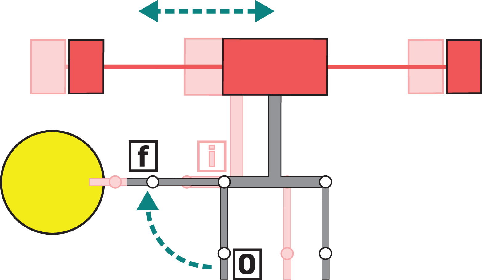
ARS-LRM spreading the left arm from initial position 0 to final position f. The UAV oscillation (shaded intermediate position i) produces a collision with the yellow obstacle. ARS-LRM: aerial robotic system with two arms for long reach manipulation. UAV: unmanned aerial vehicle.
The work begins with the “Modeling and control” section presenting the structure of the integrated platform, the corresponding multi-body dynamical model and finally the distributed control approach derived for the system. Then, in the “Motion planner with DA” section, the proposed planning algorithm is explained in detail. In order to better illustrate its benefits, the “Application scenarios” section defines two realistic industrial scenarios given by a riveting application and a chimney repairing task. After presenting the complete system as well as the motivating scenarios, the “Simulation results” section includes several simulations of the controlled ARS-LRM when following the planned trajectories to endorse the validity of the proposed algorithm. Finally, the ‘Conclusions’ section is devoted to conclusions and future work.
Modeling and control
System description
As can be seen in Figure 3, the proposed ARS-LRM consists of a multirotor with a long bar extension that incorporates a lightweight dual arm in the tip. This configuration allows aerial manipulation tasks in hard-to-reach places increasing considerably the safety distance between rotors and manipulated objects. Furthermore, the dual arm offers extended manipulation capabilities with respect to the single arm configurations existing in the literature. In this first prototype of the system, each separate arm is composed of two links, corresponding the lower one to the end effector, but further extensions of the manipulation chain are considered in future work.
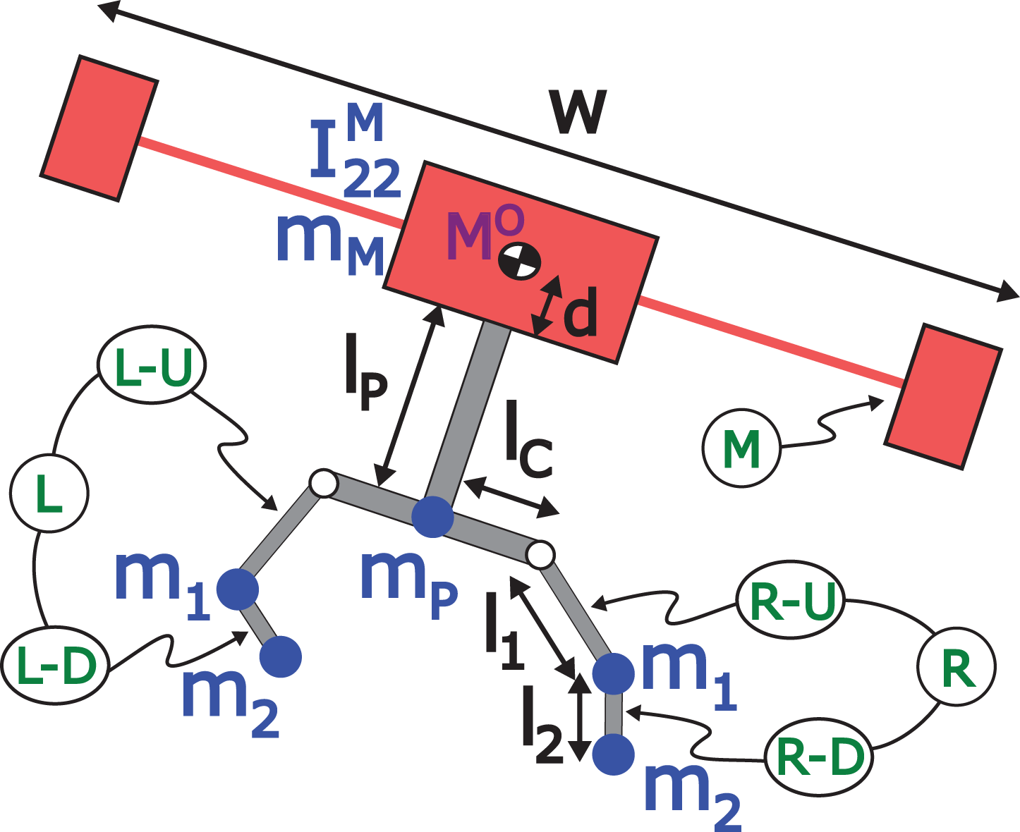
Geometry and mass distribution of the ARS-LRM. ARS-LRM: aerial robotic system with two arms for long reach manipulation.
A planar characterization of the system will serve for establishing a first proof of concept for the ARS-LRM setup. This simplified approach eases the modeling and control developments while maintaining the operation basis of the system. Following this assumption, the multirotor is characterized by a mass mM, a principal moment of inertia
ARS-LRM parameters.

ARS-LRM: aerial robotic system with two arms for long reach manipulation.
Modeling
According to Kondak et al., 18 the dynamics of a multirotor under 20 kg is mostly determined by its mechanical model. This article embraces the same assumption, and consequently the behavior of the ARS-LRM platform will be described by means of the mechanical model of the complete system. To this end, specific methodologies for multi-body systems will be applied below.
Several approaches can be found in the literature to derive equations of motion for mechanical systems. However, Kane’s method 19 has proved in Sandino et al. 20 to hold some unique advantages over other traditional approaches when addressing multi-body robotic systems like the ARS-LRM under study in this article. One of the most remarkable advantages is that the adoption of generalized speeds enables the derivation of a compact model in first-order differential equations that are uncoupled in the generalized speed derivatives. Other important features are the easy computerization as well as the computational efficiency of the resulting equations of motion.
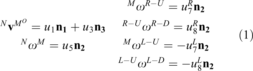
The configuration variables selected as system generalized coordinates are the longitudinal q1 and vertical q3 positions of the UAV center of mass MO in the inertial reference frame N, the multirotor pitch angle q5 and the joint angles both for left L and right R arms
where

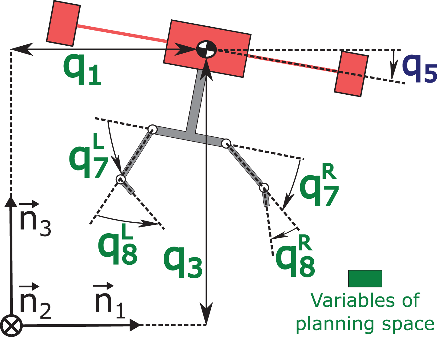
Configuration variables of the ARS-LRM model. In green, the variables selected later for the planning space. ARS-LRM: aerial robotic system with two arms for long reach manipulation.
Regarding forces and torques exerted on the ARS-LRM (see Figure 5), the rotors generate a resultant lifting force

Forces and torques applied to the ARS-LRM. ARS-LRM: aerial robotic system with two arms for long reach manipulation.
Application of Kane’s method through MotionGenesis software
21
leads to the following dynamic differential equations for translation and rotation, where

Control
After modeling the ARS-LRM, a distributed control scheme (see Figure 6) has been derived to provide the system with the capacity of executing navigation and manipulation maneuvers. The objective is the completion of the simulation environment that will allow the investigation of new planning strategies for the ARS-LRM platform. A basic control structure that makes use of nonlinear control strategies based on model inversion shall suffice to complete the test bed.

Block diagram of the distributed control scheme.
Regarding the multirotor, the control scheme is inspired by Kondak et al.
18
and consists in linearizing the system through model inversion and applying applying Proportional -Integral -Derivative (PID) control laws to the resultant dynamics. The underlying principle of control will be the adjustment of the multirotor lifting force vector, in order to generate the translational accelerations required to reduce position error. A general overview of the control scheme is shown in Figure 7, where
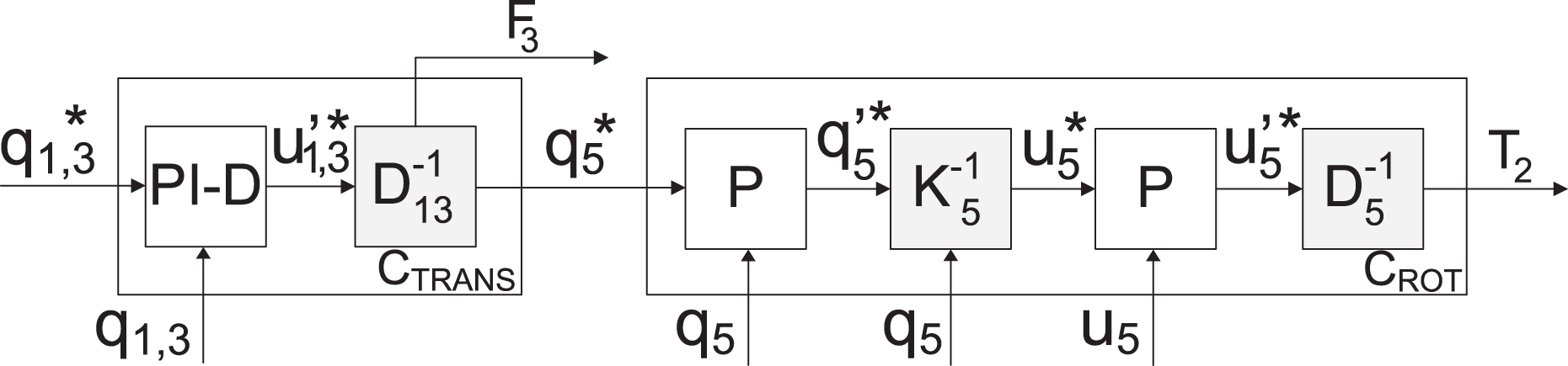
Block diagram of the UAV controller. UAV: unmanned aerial vehicle.
The control strategy selected for each arm is again based on linearization through model inversion and applying Proportional -Derivative (PD) control, which yields a nonlinear control law capable of commanding the link positions of both arms. The schematic representation of this approach is shown in Figure 8, where

Block diagram of the arm controller.
The parameters of the controllers have been tuned by means of the classic pole assignment method. The selected values constitute a trade-off that guarantees a proper dynamics range while the common mechanical limitations of this kind of systems are not overreached.
Motion planner with DA
According to Tang et al. 22 and Elbanhawi and Simic 11 , sampling-based planners like the family of RRT algorithms 23 have demonstrated high potential in finding fast solutions for high-dimensional robots. Furthermore, some of these methods bring the possibility of generating motion plans that optimize certain cost functions, as for the case of RRT* variations. 24 This makes it possible to find an optimal solution in terms of a specific metric. Taking all these considerations into account, and recalling the limited maneuverability of the ARS-LRM, an RRT*-based algorithm that optimizes energy and execution time of the planned motion has been selected for the ARS-LRM.
Another determining factor for planner performance is the planning space considered when exploring the different possibilities of motion. In this work, the planner explores jointly the configuration variables of the aerial platform (with the exception of pitch angle q5) and the dual arm, which corresponds to the variables in green color in Figure 4. This integrated strategy allows the consideration of a more complete set of system states. In this way, it is possible to achieve wider and safer operating conditions since equivalent configurations in terms of final effector positions can be differentiated according to the positions of both the multirotor and the intermediate links.
As was previously advanced, the strong dynamical coupling between the multirotor and the dual arm makes it necessary considering the dynamics of the ARS-LRM within the motion planner for robust obstacle avoidance in cluttered environments. With this purpose, the standard RRT* approach is transformed into a more advanced RRT* algorithm that incorporates DA (RRT*-DA). To this end, the expansion of the search tree is based on the behavior of the controlled system, which means that collision detection is calculated through close-loop simulations of the controlled system instead of using geometrical interpolation between states. This guarantees that the resultant planned trajectories are both free of obstacles and compatible with the dynamic constraints previously mentioned. The approach being investigated for the dynamical analysis of the tree extension is based on a root-to-candidate validation. Thus, not only the dynamical feasibility of the new possible branch reaching the candidate node is analyzed, but also the complete path from the tree root.
The pseudocode of the planning algorithm that has been developed in this work is shown in algorithm 1. It mainly corresponds to the common structure of the RRT* algorithm but some of the intermediate functionalities have been customized for the problem under study giving rise to the RRT*-DA algorithm presented in this article. These particular developments will be dealt with in detail hereafter.
RRT*-DA algorithm.

Discretization of the planning space
Due to the high dimension of the planning space integrating both UAV and manipulator states that is considered by the ARS-LRM planner (see Figure 4), a continuous treatment of the variable ranges considered in the sampling operation would require excessively elevated execution times for achieving convergent solutions. The former suggests the adoption of discretization patterns that guarantee bounded execution times for the planner. However, this discretization must be accomplished carefully since an excessively reduced set of data could endanger the algorithm convergence. Hence, there must be a trade-off between the computational gain and the convergence properties that should be determined for each application scenario.
Computation of the nearest node
The

where Δqi denotes the increment in variable qi when going from the tree node x to the sampled node
Steering
The
Collision checking
The
This operation deserves special attention since it plays an important role in the advanced functionality of the ARS-LRM planner that allows differentiating equivalent configurations in terms of final effector positions according to the positions of both the multirotor and the intermediate links. The consideration of the different geometries of the system components, together with joint exploration of the planning space for both system components, is crucial in this respect. Concerning the former, simplified models that alleviate the computational burden of collision checking, but maintaining at the same time their capability to express the heterogeneity existing in the geometry of the different parts, are the desirable option. To this end, the multirotor has been considered rectangularly shaped while the dual arm and the long bar extension are modeled by rectilinear bars with negligible section. Thus, the collision checking operation is performed with higher precision than considering only the bounding sphere associated with the ARS-LRM. This granularity eases the planner convergence to feasible trajectories in cluttered environments. Regarding the obstacles, all of them have been considered round or rectangular. In this way, it is possible to approximate complex-shaped obstacles with simple shapes that reduce the complexity of the collision checking algorithm.
Another aspect that requires further consideration is the algorithm selected for detecting the collisions. In the case of the multirotor, the approach is straightforward since it only requires checking whether the position of the center of mass is within the limits of the rectangular region that produces collisions with the obstacle (see Figure 9).
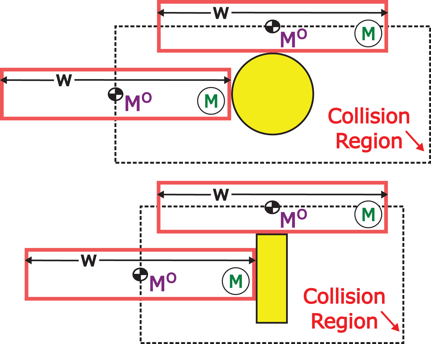
Collision checking for the multirotor based on the position of the center of mass MO. Round obstacle (above) and rectangular obstacle (below).
In contrast, the collision management for the extension bar and the dual arm admits several approaches. Although it would be possible to follow the standard procedure of generating intermediate configurations between the initial and final positions of the bar and the arm links, and then proceed to check collisions for a set of points sufficiently dense to represent each configuration, a better approach has been derived for the ARS-LRM. It mainly consists of translating the collision condition to the angular space as shown in Figure 10. In this way, the obstacles are characterized in terms of the minimum and maximum bar or link angle that may produce a collision. Then, taking into account also the distance to the obstacle, it is possible to check the collision with a considerable reduction in the computational load. Figure 11 shows two examples of this angular approach. The collision management consists of checking if a point representing certain configuration in the angular space falls inside the collision regions defined through the minimum–maximum angular characterization of the obstacles. It should be noted that the shape of such regions varies with the relative position between the multirotor and the obstacle since the distance to the obstacle employed for the collision checking is varying accordingly.

Collision checking for the right upper link. Round obstacle (left) and rectangular obstacle (right).

Regions in which the right arm collides with an obstacle for fixed UAV and obstacle positions. Round obstacle (left) and rectangular obstacle (right). The shape of the collision regions varies with the relative position between the multirotor and the obstacle. UAV: unmanned aerial vehicle.
Precomputation of collisions
In order to further reduce the execution time devoted to collision management, a precomputation of collision conditions can be implemented. For that purpose, a static environment with known-location obstacles is assumed. Then, a representative set of states for the ARS-LRM in the application scenario is selected for implementing the collision precomputation. The results are stored in a binary matrix that will allow checking collisions in two simple steps. First, the most similar element within the aforementioned set of representative states to the configuration under collision checking is searched for. Second, its corresponding value in the logic-values matrix is returned as the result for the collision checking operation. In the first step, a proper selection of the state granularity is essential to avoid false conclusions on the configuration under analysis. Taking into account that this precomputation will be executed only once for each environment, a dense discretization pattern will be used to achieve reliable results.
Computation of the set of near nodes
The

where Δqi denotes the increment in variable qi when going from the tree node x to the new candidate node
Cost functions
In order to apply the RRT* optimization sequence within the

where
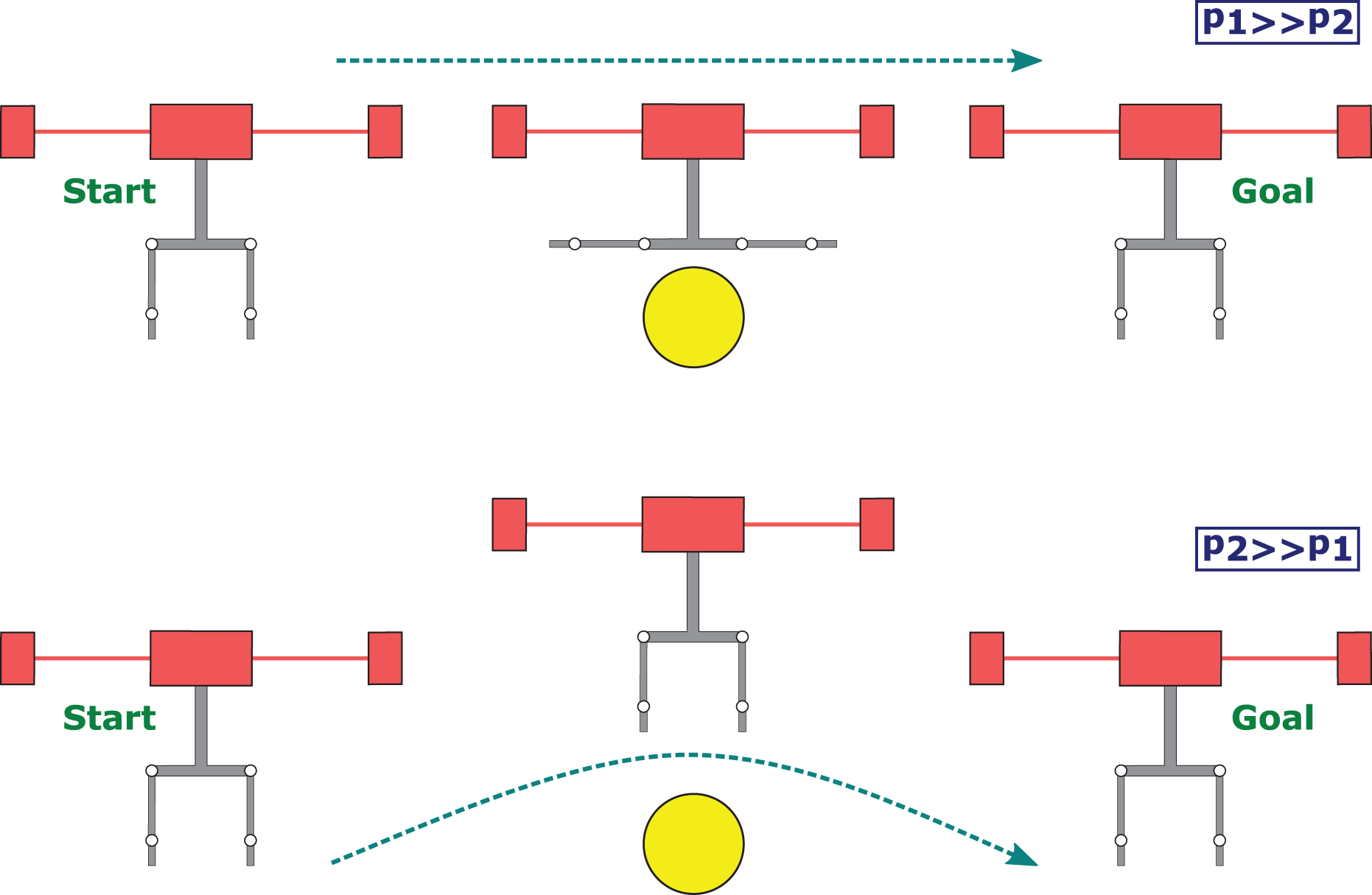
Effect of the weighting parameters p1,2 in the cost function CFE.
Dynamics awareness
The developments presented in previous subsections guarantee planned trajectories that are collision free as well as time- and energy-efficient. However, the strong dynamical coupling that exists in the ARS-LRM between the multirotor and the dual arm requires further attention since it provokes considerable differences between planned and executed trajectories. The collision risk introduced by these differences is specially critical for cluttered environments like industrial sites.
In order to solve the aforementioned problem, it is necessary to introduce DA in the planner. The resulting algorithm, RRT*-DA (RRT* with DA), guarantees robust obstacle avoidance by modifying the

Operation basis of the
Guiding obstacles to enforce manipulation patterns
In certain applications, the definition of the manipulation task implies the enforcement of certain manipulation patterns like rectilinear movements of the end effector. This kind of requirements can be addressed in the planner by means of artificial guiding obstacles that enforce the resulting trajectory to match the desired manipulation pattern. Figure 14 depicts an example of the usage of these guiding obstacles. In that scenario, the two guiding obstacles allow the right end effector to approach the yellow surface following a rectilinear movement that is perpendicular to the contact surface. In this way, other undesired trajectories that could make the end effector slides onto the surface are conveniently discarded.

Guiding obstacles enforcing a rectilinear movement perpendicular to the contact surface.
Application scenarios
In order to demonstrate the validity of the motion planning strategy presented in previous section, the algorithm will be tested in two realistic industrial scenarios, a riveting application and a chimney repairing task. Both scenarios require advanced motion planning of the ARS-LRM in order to perform robustly the desired operations in the associated cluttered environments.
Riveting application
The schematic description of this scenario is shown in Figure 15, where colored circles correspond to pipes existing in the industrial facility and surrounding circumferences denote the safety regions whose violation would be treated as a collision. As can be seen, the ARS-LRM will be commanded to place two rivets with its right arm (target points marked in red) while the left arm provides visual feedback by pointing a camera integrated as end effector (see Figure 1). In this first proof of concept, the riveting operations will assume ideal conditions, that is, absence of interaction forces.

Application scenario given by a riveting task.
The achievement of the riveting objectives defined previously requires the execution of certain intermediate operations that include both navigation and manipulation maneuvers: Navigation phase: This phase corresponds to the system displacement required to reach an observation position over the riveting area. After this, a short transition phase not requiring planner execution will enforce a ready-to-go configuration for the first riveting maneuver that will be accomplished during the manipulation phase. Manipulation phase: This phase covers the different maneuvers involved in the manipulation task under consideration, the riveting operation. In all the subphases described below, it is assumed that the left arm will adapt its configuration to optimize the visual feedback provided by its integrated camera. (a) Rivet placement: Approaching to the target point in the perpendicular direction to the target point plane by the riveting effector integrated in the right arm. (b) Release: Opposite maneuver to the rivet placement in which the riveting effector leaves the target point, again following the perpendicular direction to the target point plane. (c) Switching: Maneuver of the complete ARS-LRM to switch between the ready-to-go configurations for riveting points 1 and 2.
Chimney repairing task
This scenario is composed of two chimneys represented by four dark gray rectangles (see Figure 16). The two light gray rectangles correspond to the free space inside the chimneys and the dotted surrounding areas denote safety regions whose violations will be treated as collisions. As depicted in the figure, the ARS-LRM will be commanded to repair a crack inside the chimney (target point marked in red) with a tool located in its right arm while the left arm provides visual feedback by pointing a camera integrated as end effector (see Figure 1). It is worth noting that, thanks to the bar extension of the ARS-LRM, the aerial platform can operate out of the chimney with certain separation distance while the repairing task is being performed. This contributes to reduce the undesired aerodynamic effects that can be presented both inside the chimney as well as in its surrounding space. Again in this first proof of concept for this scenario, the repairing operation will assume ideal conditions in the chimney surface, that is, absence of interaction forces.

Application scenario given by a chimney repairing task.
Similar to the riveting application, the achievement of the repairing objectives defined previously requires the execution of certain intermediate operations that include both navigation and manipulation maneuvers: Navigation phase: This phase corresponds to the system displacement required to reach an observation position over the right chimney. After this, a short transition phase not requiring planner execution will enforce a ready-to-go configuration for the repairing maneuver that will be accomplished during the manipulation phase. Manipulation phase: This phase covers the different maneuvers involved in the manipulation task under consideration, the chimney repairing operation. In all the subphases described below, it is assumed that the left arm will adapt its configuration to optimize the visual feedback provided by its integrated camera. (a) Repair: Approaching of the tool effector integrated in the right arm to the target point in the perpendicular direction to the chimney surface. (b) Release: Opposite maneuver to the repair subphase in which the tool effector leaves the target point, again following the perpendicular direction to the chimney surface.
Simulation results
This section analyzes the results corresponding to the application of the RRT*-DA algorithm in the scenarios previously described. The simulations carried out for both scenarios have been organized around two main lines. On the one hand, the justification for the need to employ the RRT*-DA algorithm for robust obstacle avoidance in cluttered environments. To this end, the performance limitations of the basic RRT* algorithm without DA have been brought to light. On the other hand, a detailed analysis of the RRT*-DA performance in terms of the similarity between planned and executed trajectories has been also presented.
The index selected for optimization has been the cost function CFE defined in the “Cost functions” subsection. Concerning the discretizing approach presented in the “Discretization of the planning space” subsection, Table 2 shows the discretization grids adopted for both navigation and manipulation phases in the different scenarios. As can be seen, different patterns have been used in order to optimize the planner performance in each phase. Finally, it is worth mentioning that two guiding obstacles have been placed on either side of the target points. This addition will ensure a perpendicular approach of the right end effector to the target points avoiding slides onto the manipulation surfaces.
Discretization of the planning space.

Considering all the above information, the basic RRT* algorithm as well as the more advanced RRT*-DA motion planner of the ARS-LRM have been executed for both scenarios. The resultant plans (represented in the figures with light blue lines for the RRT* algorithm and with light green lines for the RRT*-DA algorithm) have been also provided to the controlled ARS-LRM in order to analyze the close-loop behavior of the system (represented in the figures with dark blue lines for the RRT* algorithm and with dark green lines for the RRT*-DA algorithm) when following the planned trajectories.
It should be clarified that the planned trajectories are calculated independently for each phase described in the “Application scenarios” section. However, the resulting trajectories are then integrated into a single one that will be given to the controller as commanded reference. Consequently, there are no different phases from the point of view of the system/control execution. The simulation work has been carried out in a MATLAB–Simulink framework that provides the graphical evolution of the system variables as well as the corresponding virtual reality animations. Both graphical outputs will be used throughout this section to illustrate the obtained results.
Results using the RRT* algorithm
The basic RRT* algorithm has certain performance limitations since it does not consider the dynamics of the system. For instance, dynamic effects like oscillations are not accounted for during the collision-checking phase, which may produce risky situations when commanding the planned trajectory to the real system. In order to illustrate the potential impact of this missing feature, two complete simulations with the RRT* algorithm including both the planned and the close-loop trajectories have been considered for the two scenarios under study (see the corresponding animations 25 ). According to these simulations, the basic RRT* algorithm plans efficient trajectories for navigation and manipulation phases in both scenarios. However, the corresponding close-loop trajectories described by the controlled ARS-LRM do not satisfy the desired collision-free and slide-free properties. For the riveting scenario, Figure 17 shows how the ARS-LRM violates safety margins during the navigation phase, whereas Figure 18 reveals a slide onto the pipe surface during the manipulation phase. Similarly, for the chimney scenario, Figure 19 illustrates a collision of the right end effector with chimney surface.
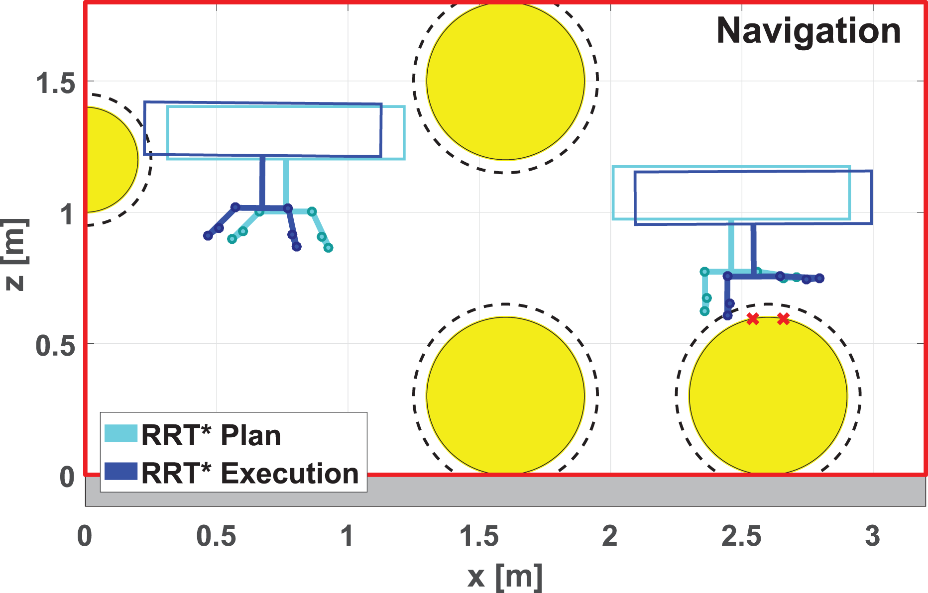
Riveting scenario. Navigation phase planned with the RRT* algorithm. The planned trajectory is collision-free but not the trajectory executed by the controlled ARS-LRM. RRT* algorithm: optimal Rapidly-exploring Random Tree algorithm; ARS-LRM: aerial robotic system with two arms for long reach manipulation.

Riveting scenario. Manipulation phase (rivet placement 1) planned with the RRT* algorithm. The dotted lines represent the simulated movements of both the multirotor center of mass and the right end effector. The trajectory executed by the controlled ARS-LRM (from initial configuration 0 to final configuration f through shaded intermediate configuration i) violates a guiding obstacle and consequently the right end effector slides onto the pipe surface. RRT* algorithm: optimal Rapidly-exploring Random Tree algorithm; ARS-LRM: aerial robotic system with two arms for long reach manipulation.

Chimney scenario. Manipulation phase (repair) planned with the RRT* algorithm. The dotted lines represent the simulated movements of both the multirotor center of mass and the right end effector. The trajectory executed by the controlled ARS-LRM (from initial configuration 0 to final configuration f through shaded intermediate configuration i) violates a guiding obstacle and consequently the right end effector collides with the chimney surface. RRT* algorithm: optimal Rapidly-exploring Random Tree algorithm; ARS-LRM: aerial robotic system with two arms for long reach manipulation.
Results using the RRT*-DA algorithm
The previous subsection motivated the need to consider the dynamics of the system within the motion planning problem when operating in cluttered environments. To solve the above, the RRT*-DA algorithm has been proposed in this article. This section is devoted to analyze the performance of such algorithm in the same simulation scenarios that were used in previous subsection with the basic RRT* algorithm (see the corresponding animations 26,27 ). To this end, again both the planned and the close-loop trajectories will be studied.
The results corresponding to the navigation phase of both scenarios are presented together, Figures 20 and 21 for the riveting scenario, whereas Figures 22 and 23 corresponds to the chimney scenario. The trajectory followed by the ARS-LRM is illustrated by the dotted line representing the movement of the multirotor center of mass MO from initial configuration 0 to final configuration f through intermediate configurations i1,2,.... As can be observed, in both scenarios, the planned trajectory commands safely and efficiently the controlled ARS-LRM through the navigation phase.

Riveting scenario. Navigation phase planned with the RRT*-DA algorithm and executed by the controlled ARS-LRM. The dotted line represents the simulated movement of the multirotor center of mass MO from initial configuration 0 to final configuration f through intermediate configurations i1,2,3. The ARS-LRM navigates through the obstacles following an efficient and collision-free trajectory. RRT*-DA algorithm: optimal Rapidly-exploring Random Tree algorithm that incorporates dynamics awareness; ARS-LRM: aerial robotic system with two arms for long reach manipulation.
Riveting scenario. Navigation phase planned with the RRT*-DA algorithm (light green) and executed by the controlled ARS-LRM (dark green). RRT*-DA algorithm: optimal Rapidly-exploring Random Tree algorithm that incorporates dynamics awareness; ARS-LRM: aerial robotic system with two arms for long reach manipulation.

Chimney scenario. Navigation phase planned with the RRT*-DA algorithm and executed by the controlled ARS-LRM. The dotted line represents the simulated movement of the multirotor center of mass MO from initial configuration 0 to final configuration f through intermediate configurations i1,2. The ARS-LRM navigates through the obstacles following an efficient and collision-free trajectory. RRT*-DA algorithm: optimal Rapidly-exploring Random Tree algorithm that incorporates dynamics awareness; ARS-LRM: aerial robotic system with two arms for long reach manipulation.
Chimney scenario. Navigation phase planned with the RRT*-DA algorithm (light green) and executed by the controlled ARS-LRM (dark green). RRT*-DA algorithm: optimal Rapidly-exploring Random Tree algorithm that incorporates dynamics awareness; ARS-LRM: aerial robotic system with two arms for long reach manipulation.
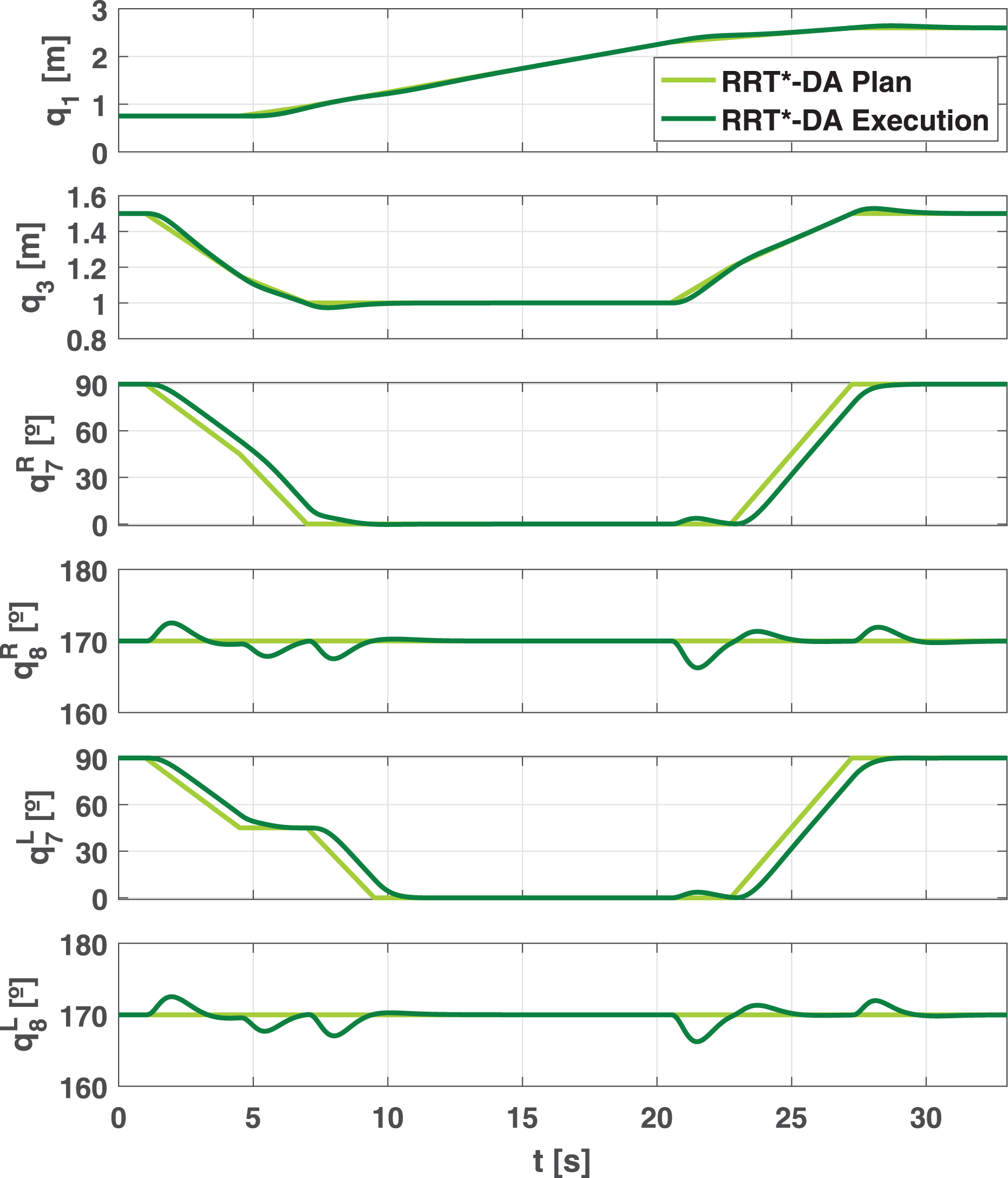
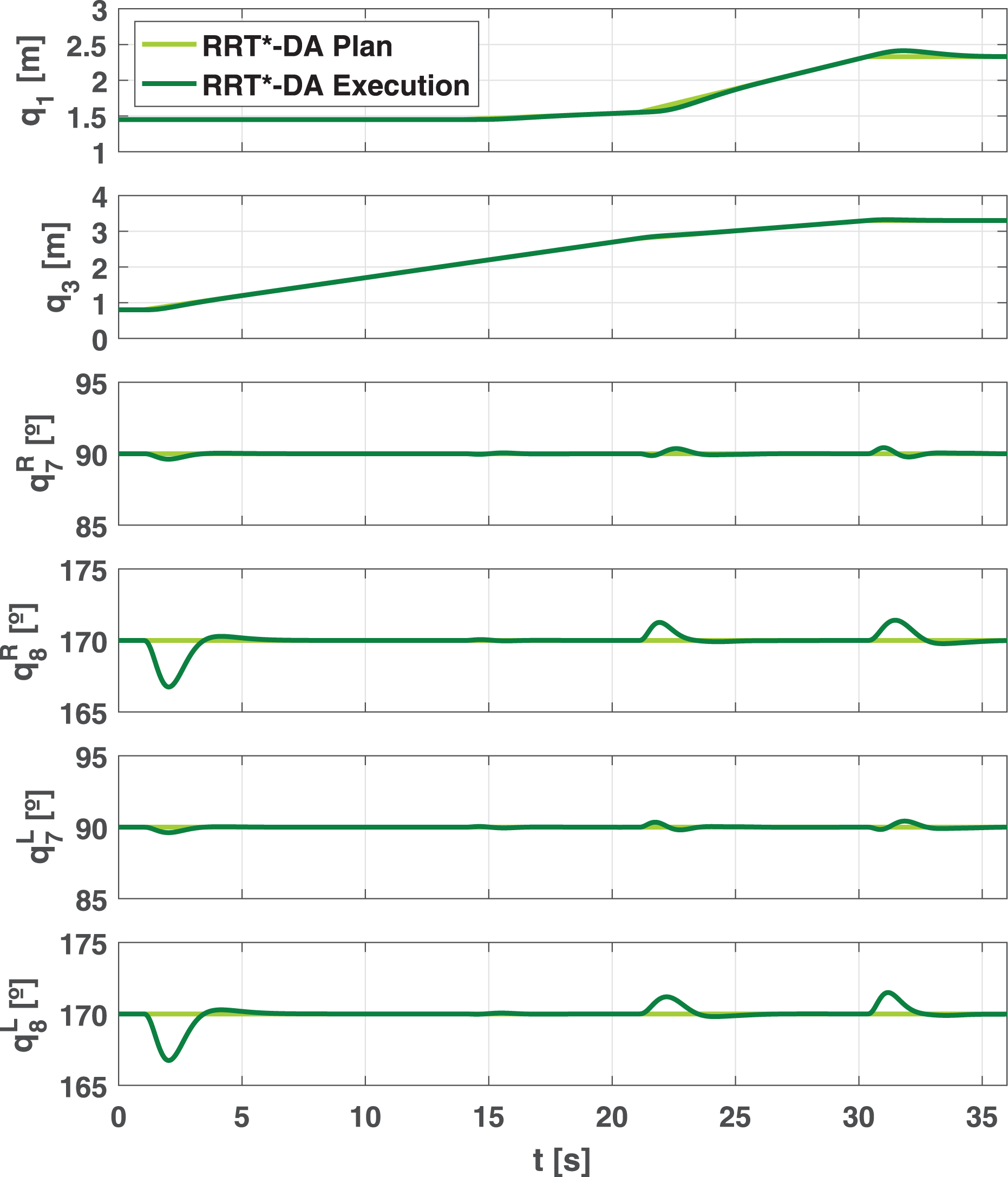
Regarding the manipulation phase, Figures 24 and 25 present the achieved results for the riveting scenario. As in the navigation phase, Figure 24 shows a schematic representation of the maneuvers associated with the manipulation phase where the dotted lines represent the simulated movements of both the multirotor center of mass MO and the right end effector from initial configurations 0 to final configurations f. Similarly, in Figure 25, the evolution of the planning-space variables, for both the planned trajectory (light green line) and the close-loop executed trajectory (dark green line), has been represented for this manipulation phase. Once again the planned trajectory succeeds in commanding efficiently the controlled ARS-LRM through the different manipulation maneuvers involved in the riveting task. In contrast to the results using the basic RRT* algorithm, the guiding obstacles are not violated, and hence, the right end effector executes the rivet placements without any slide onto the pipe surface. Moreover, Figure 24 (switching) illustrates how the joint consideration of the planning space for the multirotor and the dual arm allows the optimization of the switching maneuver between the riveting points. More precisely, the motion planner takes advantage of the multirotor vertical displacement (see the shaded intermediate configuration i) to carry out the switching maneuver of the riveting effector in a more efficient way. Turning now to the chimney repairing scenario, Figures 26 and 27 show the results corresponding to the manipulation scenario. Once more, the planned trajectory commands the ARS-LRM through an efficient and collision-free trajectory.
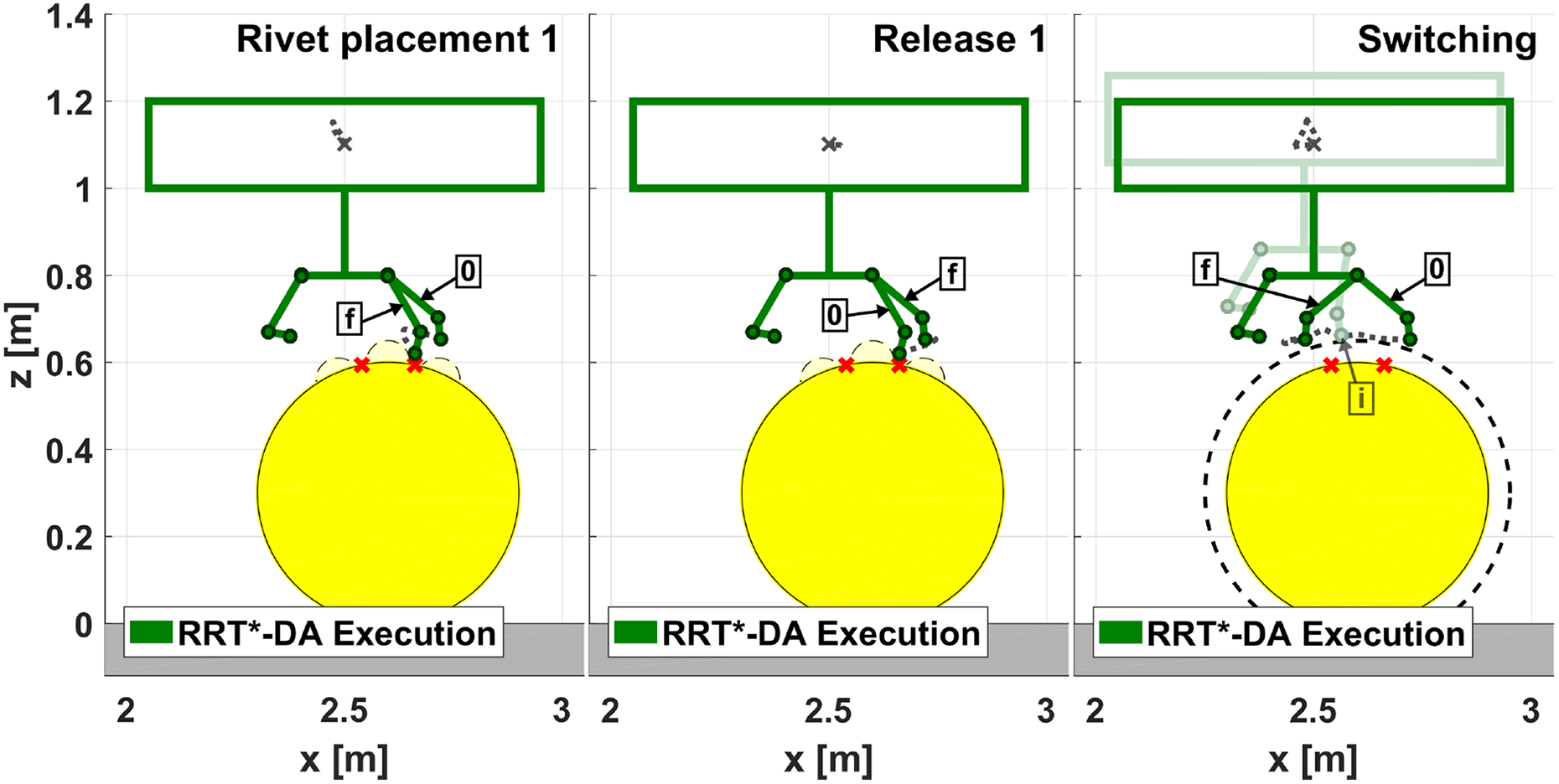
Riveting scenario. Manipulation phase planned with the RRT*-DA algorithm and executed by the controlled ARS-LRM. The dotted lines represent the simulated movements of both the multirotor center of mass MO and the right end effector from initial configurations 0 to final configurations f. The ARS-LRM places the first rivet and then switches efficiently (see the shaded intermediate configuration i) between the ready-to-go configurations. RRT*-DA algorithm: optimal Rapidly-exploring Random Tree algorithm that incorporates dynamics awareness; ARS-LRM: aerial robotic system with two arms for long reach manipulation.

Riveting scenario. Manipulation phase planned with the RRT*-DA algorithm (light green) and executed by the controlled ARS-LRM (dark green). RRT*-DA algorithm: optimal Rapidly-exploring Random Tree algorithm that incorporates dynamics awareness; ARS-LRM: aerial robotic system with two arms for long reach manipulation.

Chimney scenario. Manipulation phase planned with the RRT*-DA algorithm and executed by the controlled ARS-LRM. The dotted lines represent the simulated movements of both the multirotor center of mass M o and the right end effector from initial configurations 0 to final configurations f through intermediate configuration i. The ARS-LRM approaches and moves away the right end effector to the target point in the chimney surface following perpendicular movements. RRT*-DA algorithm: optimal Rapidly-exploring Random Tree algorithm that incorporates dynamics awareness; ARS-LRM: aerial robotic system with two arms for long reach manipulation.

Chimney scenario. Manipulation phase planned with the RRT*-DA algorithm (light green) and executed by the controlled ARS-LRM (dark green). RRT*-DA algorithm: optimal Rapidly-exploring Random Tree algorithm that incorporates dynamics awareness; ARS-LRM: aerial robotic system with two arms for long reach manipulation.
Conclusions
This article extends previous works of the authors in the field of motion planning strategies for aerial robotic systems. The most relevant contribution is the inclusion of DA in the motion planner derived for an ARS-LRM since this feature guarantees robust obstacle avoidance in cluttered environments.
In order to evaluate the algorithms under consideration, a simulation environment that characterizes the relevant system behaviors for planner operation was required. Consistently with this requirement, the ARS-LRM platform has been described in detail together with its potential benefits: a considerable increment in the safety distance between rotors and manipulated objects, the capability to execute tasks in hard-to-reach places, and the extended manipulation capabilities offered by the dual arm. Taking this description as reference, the dynamics of the system has been modeled with specific methodologies for multi-body systems. Furthermore, a distributed control scheme that makes use of nonlinear control strategies based on model inversion has been derived to complete the test bed.
With respect to the presented RRT*-DA planning approach, several features justify the relevance of this contribution. The aerial platform and the dual arm device have been considered jointly within the planner operation. In this way, it is possible to achieve wider and safer operating conditions since equivalent configurations in terms of final effector positions can be differentiated according to the positions of both the multirotor and the intermediate links. On the other hand, the planner operation is driven by an RRT*-based algorithm that optimizes energy and execution time in cluttered environments for both navigation and manipulation tasks. Finally, the aforementioned feature of DA guarantees robust obstacle avoidance.
With the purpose of demonstrating the validity of the motion planning strategy presented, the RRT*-DA algorithm has been tested in two realistic industrial scenarios, a riveting application and a chimney repairing task. As was discussed in the simulation section, the planned trajectories succeed in commanding efficiently the controlled ARS-LRM through navigation and manipulation phases without producing collisions with the obstacles existing in the scenarios. The latter has been proved not to be possible using the basic RRT* algorithm without DA.
Regarding future extensions of the work, the presented results will be completed with a three-dimensional characterization of the ARS-LRM. Then, experimental validation will be carried out by extending the platform prototype presented by Suarez et al. 7 Finally, due to the relevance of the aerodynamic effects when an aerial platform operates close to other surfaces in cluttered environments, the motion planning strategies will be extended to account for such aerodynamic effects.
Footnotes
Declaration of conflicting interests
The author(s) declared no potential conflicts of interest with respect to the research, authorship, and/or publication of this article.
Funding
The author(s) disclosed receipt of the following financial support for the research, authorship and/or publication of this article: This work has been supported by the European Project AEROARMS, funded by the Horizon 2020 research and innovation program of the European Commission under grant agreement no. 644271 and by the AEROMAIN project of the Spanish RETOS Program DPI2014-59383-C2-1-R.