
Abstract
In the process of grasping objects by robot, the uncertainty of the object pose has greater impact on the stability of grasping. In this article, an adaptive grasping strategy is proposed to solve the problem of pose uncertainty in the grasping process. The strategy is based on the finger state function to switch control method, so as to realize the contact with the object by the fingers, and the application of grasp force to ensure the pre-grasp stability of the object; then, the object pose error is estimated through the contact between finger and object, and the pose error of the object is compensated according to the different error ranges to reduce the influence of the pose error on the grasp stability. Finally, the grasping experiments by humanoid robot are carried out to verify the performance of the adaptive grasping method proposed in this article.
Introduction
The grasp of unknown objects is the basic ability for robots to perform a variety of complex tasks instead of hand. When the object model and pose are accurately known, a set of points that meet the requirements of grasp can be obtained by grasp planning, and the fingers reach the grasp point and apply the grasp force according to the trajectory planning so as to complete the stable grasp of the object. However, the actual grasp is a dynamic process with a variety of uncertainties. In the uncertainty of the grasp, the pose error of the object is ubiquitous and has a great influence on the grasp, which may be resulted from the following aspects: (1) the location error of the sensor, including location sensor, tactile sensor, and visual sensor; (2) a slight collision between the robot and the object in the course of the implementation, resulting in a slight change in the location of the object; and (3) model reconstruction error of the object. These errors will make the actual grasp inconsistent with the grasp plan, resulting in the low quality of actual grasp or even the fail of grasp.
Due to the inherent error of the robot, the relative position of the object and the finger can only be approximately known, which makes it difficult for the fingertip to be in precise contact with the object at the position obtained by the analysis. In response to these questions, Nguyen 1 defined the concept of independent contact regions (ICRs). The method for calculating ICR was proposed by Roa and Suárez 2 and Krug et al. 3 . Zheng and Qian 4 analyzed the effects of friction uncertainty and the uncertainty of the contact position on the sealing force in the grasping object and modeled the two uncertainties through rigorous mathematical description. Weisz and Allen 5 put forward better evaluation indicator P(fc) to evaluate grasp uncertainty for grasp stability. Kim et al. 6,7 studied how to evaluate the stability of the object grasp with pose uncertainty by the grasp quality and proposed a quality evaluation indicator for the consideration of the contact dynamics and pose uncertainty.
Some methods are used to estimate the uncertainty directly for errors in the position of object. Chalon et al. 8 proposed an online method for estimating the pose of object based on the particle filter to accurately estimate the pose of the object to be grasped, for the change of pose after grasp. Zhang and Trinkle 9 also used the particle filter to simultaneously estimate the physical parameters of the object and to track the object when it is pushed. There are other ways to reduce the impact of uncertainty from the perspective of control strategies. Dragiev et al. 10 proposed a control law for the grasp and exploration of unknown objects to select the grasp area of the model. Su et al. 11 proposed a grasp strategy based on the softness of under-actuated hand for the object position error, by which the stable grasp can be completed through the optimization of the grasp trajectory planning and sensor-based adjustment. Chen et al. 12 proposed an adaptive compliant grasp strategy to improve the impact of position uncertainty on self-grasp. There are also some studies based on learning and heuristic methods. Hsiao et al. 13 proposed a heuristic grasp selection method based on the local features of unknown objects. In addition, a decision-theoretical method is also proposed to reduce the impact of the object attitude error on the grasp for the known shape of the object and the high premise mobility of the robot. 14,15 Stulp et al. 16 proposed a grasp optimization method for uncertainty state estimation. Kehoe et al. 17 studied the object position error and proposed a grasp algorithm that applies cloud computing structure based on the parallel gripper grasp. Guo et al. proposed an end-to-end deep vision network model to predict possible good grasps from real-world images in real time. 18,19
In order to enable the robot to perform tasks in the human environment, the grasp of uncertainty is one of the urgent problems to be solved. The current research on grasp uncertainty has been taken from the aspects of grasp control method, grasp quality assessment, pose error estimation, and grasp task space to increase the stability. The approach used includes both the improvement to traditional grasp methods and the decision-making and learning-based approaches. Each of the abovementioned research methods has limitation. The impact of uncertainty on the grasp has not yet been eliminated, so it is still worthy of study in dexterous grasp.
In this article, a multi-controller–based method to stably grasp a known object is proposed. The main challenge of the grasp comes from the pose uncertainty of object. To this end, the whole grasping procedure is divided into three stages, namely approaching, pre-grasp, and grasping. The contacts between multi-fingertips and object are established in pre-grasp, and the pose error is estimated using the tactile feedback and forward kinematics of robot hand. Finally, Q-distance is used as the criterion of grasp stability to improve the grasp performance considering the compensation of pose error.
The main contribution of this article is as follows. A new adaptive grasp strategy is proposed for the failure of the grasp by robot caused by the pose error. Based on the force coordination strategy, the stable grasp is realized in the presence of the pose uncertainty through the estimation and compensation of the pose error by tactile information.
Background
Hand controller
Two types of controllers are used in the grasping: impedence controller and force controller.
Impedance controller
Based on the detected force information, the adjustment values of position, velocity, and acceleration are obtained by position-based impedance control and according to the calculation using the expected impedance relation, and then, the adjusted target position is tracked and controlled by the position loop to realize the flexibility of the contact space and, meanwhile, ensure the accuracy of the free space position. The control law is shown as follows

where
Force controller
The size of the external force of the finger

Grasp planner based on finite-state machine
We use state-action space defined in the semantic level to describe the switch strategy of grasp planner. In action space:
In state space:
where
For the ith finger, the state function of finger is defined as
Grasp quality metric
Grasp stability should be firstly considered in the grasping process. In order to measure the disturbance resistance ability of a grasp, some grasp quality measures are proposed. Q-distance metric 20 is chosen to measure the stability of grasp, and it is defined as follows

The geometric description of this metric is consistent with the previous defined grasp quality measures,
21
but it can measure the grasp with or without force closure (FC). A grasp is FC if and only if
Adaptive grasp strategy for object pose uncertainty
The process of grasping objects is dynamic, which can be divided into three stages in this article: approach, contact, and grasp. When the dexterous hand reaches the designated position through the robot arm, the fingers of dexterous hand firstly move to the target point, and then, the finger comes into contact with the target point and exerts contact force to complete the grasp. When the object has a pose error, it may cause the following problems: (1) the fingers may contact with the object one after another in the process of grasp, which cannot be resolved by speed planning. As the grasp is not closed at this time, the finger contacting the object is equivalent to applying an interference torque to the object, resulting in an unstable state of the object during contact; (2) the finger does not come into contact with the object at the target point of position, but it is in contact with the neighborhood of the desired point or even fails in reaching the object, which may cause the low quality of grasp or even failure. The adaptive grasp strategy in this section will focus on these two aspects.
A multi-finger cooperative control for adaptive grasp
In this section, a multi-finger cooperative control strategy is designed for grasp objects. The strategy is based on finger impedance control and force control, by which the fingers contact with the object one after another through the coordination of each finger movement in the grasp process; meanwhile, the grasp force is exerted to avoid the instability in the process of grasp. In order to distinguish from the grasp process of object, the stage of maintaining a small contact force in the contact between the finger and the object without grasp force applied is called pre-grasp. During the grasp process, the state of the finger relative to the object is switched from approaching, contacting, and applying the grasping force, respectively. Different control methods are switched by judging the different states of the fingers during the grasp process to ensure the stability of the pre-grasp process.
When
The position-based impedance control in the Cartesian space is used when the finger begins to move. When
Design of finger controller
The controller of the finger is the basis for implementing the multi-finger coordination strategy proposed in the previous section. In addition to ensuring the accuracy of the position, it is necessary to ensure a certain degree of flexibility, in order to avoid damage to objects and fingers; it shall keep as little contact force as possible to avoid pushing the object in the contact stage. So in the stage of grasping object, the position-based impedance control is applied to complete the grasp; and in contact stage between the finger and the object, the finger force control is applied to achieve precise control of the contact force.
Figure 1 shows the structure diagram of the controller used in the finger. The controller includes impedance control and force control, and the switching condition of the controller is determined by the state function vector of the finger

Diagram of a finger controller.
Estimation of pose error of objects based on pre-grasp tactile information
Even if the multi-force coordination strategy is used to ensure the stability of the pre-grasp process, the final grasp point will change and the quality of grasp may be affected due to the presence of the object position error. Therefore, in this section, how to estimate the pose error of the object by the information obtained in the pre-grasp process is mainly discussed.
In the pre-grasp process, the actual contact point between the finger and the object can be obtained by the arm–hand kinematics based on the tactile information. Using the object model, the expected contact point, and the actual contact point information, the pose error of the object can be calculated by geometric calculation. The pose error discussed in this article is limited to the extent that the pose error does not cause the hand to collide with the object or move away from the hand when approaching the object.
Several common objects, such as spheres, cuboids, cylinders, and vertebral, are taken for analysis. For the objects placed on a plane, the pose error in grasp includes the position error and attitude error on the plane. The definition of the object coordinate system is used in this chapter. Therefore, for the rotating body (such as sphere, cylinder, and cone), the error includes only the position error of the object in the plane (Δx, Δy); for the nonrotating body (cuboids and triple prisms), the angular error (Δθ) around the z-axis is also included in addition to the position error. The pose error estimations of the rotor and the nonrotating body are discussed by taking the sphere and the rectangular object as examples.
Figure 2 shows a grasp scenario, and the related coordinate frames and pose error are defined. The object with the height h is placed at the origin of the coordinate system, the center of mass is

Grasp scenario.

Model projection when grasping the ball.
For a sphere, let the radius of the sphere be R, then, the distance from the axis of symmetry of the object to the contact point can be expressed as follows


When the number of contact points i ≥ 3, the object position errors Δx and Δy can be obtained from equations (5) and (6) as follows

where
Similarly, the positional deviation of the rotors such as cylinders and frustums can be solved in this kind of manner.
For the box, it may also include posture deviation in addition to the position deviation. As the object is placed on the plane, only the attitude deviation (Δθ) around the z-axis is considered. Attitude deviation is usually more difficult to compensate with fingers. So two adjustments are adopted, as shown in Figure 4. First, the attitude deviation angle (Δθ) is estimated, and the attitude deviation is compensated by the motion of the manipulator; after adjustment, the new position is obtained and the position deviation is estimated by the following
where

Model projection when grasping the cuboid includes pose error.
The position deviation is then estimated again by pre-grasp, and the final grasp is finished using the adjustment method for the second position compensation.


where
In this way, the pose deviation of the object by the dexterous hand can be estimated by one or two pre-grasps. As can be seen from Figures 2 and 3, when pose error exists, the fingers may not be in contact with the object or with the unplanned location. In the previous grasp planning, we have obtained the optimal grasp points, so the pose error will lead to a decline in the quality of the grasp. Therefore, the next section will continue to explore how to use the robot arm or finger to compensate for the deviation to ensure the stability of the grasp.
Adaptive grasp strategy based on pose error compensation
After the error of the object position is obtained, the error can be compensated by finger or hand. In addition, how to compensate for the error needs the analysis on the impact of different error ranges and different compensation methods on the stability of the grasp.
Analysis on the effect of pose error compensation on grasp stability
In order to evaluate the performance of multi-fingered grasp of objects, the researchers proposed a variety of indicators for different task requirements to assess the grasp, and these indicators are usually called grasp quality. In many indicators for the evaluation of the stability, Q-distance is selected as the evaluation indictor of grasp stability in this article. 20
When pose error exists, the failure of contact between the finger and the object may happen from the start to the desired location for some of the fingers. In order to ensure that the fingers are in full contact with the object, the finger is planned to move in a straight line along the direction of the desired contact force until it comes into contact with the object.
As shown in Figure 5, the spheroid with Φ = 72 mm is taken, for example, in which the dexterous hand is driven by the robot arm along the z-axis of the object coordinate system to approach, and there are four fingers in contact with the object. The initial positions of the fingers are

Grasping the ball after fingers compensate for the position error when Δx = 12.5 mm and Δy = −12.5 mm.
The error is converted to the finger coordinate system and compensated by the finger, in which gray dotted line means the trajectory of the finger after adjusting the target point. The object is moved from the initial position to the expected position along the straight trajectory, where the ring finger (I4) is in contact (F4) with the object before reaching the desired position (E4) and stops the movement,
In order to evaluate the impact of the two plans on the grasp quality more generally, the origin is taken as the starting point,
Figure 6 shows the grasp quality distribution in which the error is not compensated when there is a position error in the sphere. The position of the object in the plane x − y is represented by a number of identical squares, and the area of each box is 5 × 5 mm2, where the brown–black box area is defined as reg_grasp, indicating the dexterous hand can grasp the object within the scope, the color from deep to shallow means the value dQ from small to large in this position; and white square area is recorded as reg_out, which indicates the flexible workspace of the object out of the finger or the interfering area of the initial grasp position of the finger with the object, in which the object cannot be grasped. In reg_grasp, all the regions that dQ < 0 are recorded as reg_fc, and the blue dashed line indicates the convex hull of the area

where count indicates the number of the square units that reg_fc included.

Grasp quality distribution map when grasping the object directly.
Figure 7 shows the grasp quality distribution when the finger compensation error is used. When the grasp is completed by the finger compensation method, the finger may be moved beyond the feasible contact area by compensating the motion plan, and the nearest point in the area from the new planning point is selected as the expected contact point. In Figure 7, there are 67 square regions that meet the requirement of close force grasp, and the average grasp quality indicator is

Grasp quality distribution when grasping the sphere with finger compensation.
According to the grasp quality distribution shown in Figure 7, when the error is in the smaller range, the quality of grasp is significantly improved compared with that in Figure 6; but when the error is large, the finger cannot completely compensate the position error due to kinematics and operability, which is the reason for the slight decrease in the average grasp quality, which is also the main problem of error compensation by finger. Therefore, when the error is beyond the adjustable range of finger greatly, the compensation error by finger does not mean the improvement of grasping stability. At this time, the complete compensation through the robot arm will ensure the contact of the fingers consistent with planning point.
For nonrotating bodies (such as cuboids and triangular prisms), the situation is more complex, of which the position uncertainty includes the position error and plane rotation angle error Δθ. Taking the rectangular box with the size of a = 40 mm, b = 60 mm, and h = 200 mm, for example, the initial position of the object is coordinate system origin, with the initial angle θ = 10°. As shown in Figure 8, there are five fingers in contact with the object, and the resulting grasp quality is dQ = −0.37.

Grasping the cuboid after fingers compensate for the position error when Δx = 7.5 mm, Δy = 12.5 mm, and Δθ = −20°.
The actual pose error of the object is set as Δx = 7.5 mm, Δy = 12.5 mm, and Δθ = −20°. Figure 8 shows the replanning grasp expectation points after the compensation for the position error only by the finger. The fingers are not beyond the workspace, and the actual point of contact
In order to evaluate the effect of the cuboid pose error on grasp more comprehensively, the angle of the object is changed with the step δθ = 5°, and after each time, the position of the object is changed at the same time with δx = 5 mm and δy = 5 mm as step. Considering the actual grasp situation, the angle error is limited in

Grasp quality distribution when grasping cuboid with pose error.
In order to more intuitively compare the influence of the angle error on the grasp quality, the number of the squares count and the corresponding values of

The number of the count squares and the corresponding values of
Therefore, for nonrotating bodies, the posture error has a great influence on the grasp stability, and it is necessary to compensate for the posture error. As it is difficult to compensate the angular error through the three-degree-of-freedom (3-DOF) fingers, the application of the robot arm with more freedom is more reasonable. The following conclusions can be drawn from the abovementioned simulation analysis for different shapes and sizes of objects: (1) In the grasp, the position error has a great influence on the rotating body, and the angle error has a great influence on the nonrotating body. The effect of the position error on the nonrotating body is smaller than that of the rotating body. (2) The direction of principal axis in reg_grasp is vertical to the pinching direction of the dexterous hand thumb and the rest of the fingers. (3) In a small error range, the grasp quality has no significant change; when the pose error of the object is small, the use of force collaboration grasp strategy without compensation for the error does not affect the grasp stability.
Compensation strategy for pose error
This article adopts the hierarchical error compensation strategy. After estimating the current pose error of the object by the pre-grasp, the expected position of the finger is adjusted according to the pose error, and the grasp is repeated with the dexterity compensation error of the finger. As the adjustment of the finger is limited, when the error of the object is small, the adjustment of the finger can still compensate for the error and complete the grasp; when the object model or pose error is large, with the kinematics and operability constraints, finger adjustment will not be able to fully compensate for the error. In addition, the dexterous hand fingers have less freedom, so the angle error cannot be adjusted by finger. At this time, the use of the robot arm with more DOFs in the adjustment of the initial grasp location and posture becomes a better solution.
First, the position error function of the object is defined as follows

According to the analysis on the grasp quality distribution, the error can be divided into the following three intervals:
The adaptive error compensation strategy for the grasp of object by dexterous hand is shown in Figure 11. The model and pose of the object are known, and the expected contact point is obtained by the grasp planning. When the robotic arm sends the dexterous hand to the specified position, the finger starts to grasp. The entire grasp process is based on the force collaboration grasp strategy. The finger moves to the target position until it comes into contact with the object and maintains a small contact force. When all the expected fingers come into contact with the object, the finger touch and position sensor values are recorded, getting the actual contact point. According to the object model and the expected contact point, the object pose error is calculated.

Flowchart of adaptive grasp strategy.
For rotating bodies and nonrotating bodies without posture deviation, the position error types are classified. When
The difference between compensating the error by the robot arm and the finger is that the finger compensation error only needs to be replanned; while the robot arm movement needs to be programmed first and then replan the grasp after the movement, which increases the moving time. The adoption of the robot arm for error compensation needs the comprehensive consideration for task requirements for grasp time and stability.
According to the abovementioned adaptive grasp strategies, even if the object has pose error, it can be compensated and the final grasp can be completed as long as the object is still in the dexterous workspace.
Adaptive grasp experiment
The five-fingered robot hand DLR/HIT Hand II is multisensory and highly integrated, and each finger has 3 DOFs and four joints. 23 The tactile sensor is made of pressure conductive rubber and mounted on the curved 3-D convex surface of fingertip. In the grasping experiment, the DLR/HIT Hand II is mounted on the wrist of 7-DOF robot arm, as shown in Figure 12. A set of object prototypes and daily objects are used in the experiment. Figure 13 shows the database of the objects in grasp experiment. All the objects belong to five standard shapes, and there are six objects of different dimensions for each shape.

DLR/HIT Hand II and 7-DOF robot arm. DOF: degree of freedom.

Database of the objects in grasp experiment.
In order to verify the validity of the adaptive grasp method proposed in this chapter, a total of 15 objects of four types were selected for the existence of pose error. According to the analysis on the impact of posture error on the stability,
The coordinate paper is pasted on the experimental platform, and the object is placed at the origin of the coordinate system of the coordinate paper, by which the actual pose error of the object can be accurately recorded, in order to facilitate the comparison in the experiment with the estimated pose error by dexterous hand finger. In the experiment, the object is first placed at the origin of the object coordinate system, and the object is pushed according to the scale of the standard paper to create the expected pose error. When Δx = 15 mm and Δy = −10 mm, the force is only used in conjunction with the grasp strategy without error compensation, and as shown in Figure 14, the thumb contacts with the object first, the index finger and middle finger continue the movement to contact with the object after reaching the expected position (Figure 14(d) and (e)). Although the method can ensure that three fingers are in contact with the object (Figure 14(f)), the force-closure grasp is not formed due to large position error, so the final grasp fails (Figure 14(g)). Because of the simultaneous contact strategy, the whole process of grasping objects is stable.

The process of grasping the ball by force collaborative grasp strategy when Δx = 15 mm and Δy = −10 mm.
When the adaptive grasp method is used, the error is compensated by finger movement as Δp = 18 and

The process of grasping the ball by adaptive grasp strategy when Δx = 15 mm and Δy = −10 mm.

(a) to (c) Fingertip positions, (d) and (e) forces, and (f) state function in finger coordinate when grasping by adaptive grasp strategy (Δx = 15 mm and Δy = −10 mm).
When the error range is further expanded, and limited by finger kinematics and finger maneuverability requirements, the adjustment of the finger cannot completely compensate for the position error of the object. For example, when the object error reaches Δx = 25 mm and Δy = −10 mm, Δp = 27 and
According to the error range of object, this error should be compensated by the movement of the robot arm. Figure 17 shows the grasp process by the use of error compensation method. As the object error is too large, the index finger contacts with the object through the four compensation movements after reaching the expected position (Figure 17(d) and (e)); when all the expected fingers contact with objects, object position deviation can be obtained according to the calculations of fingertips and joint angle readings Δp = 27 and
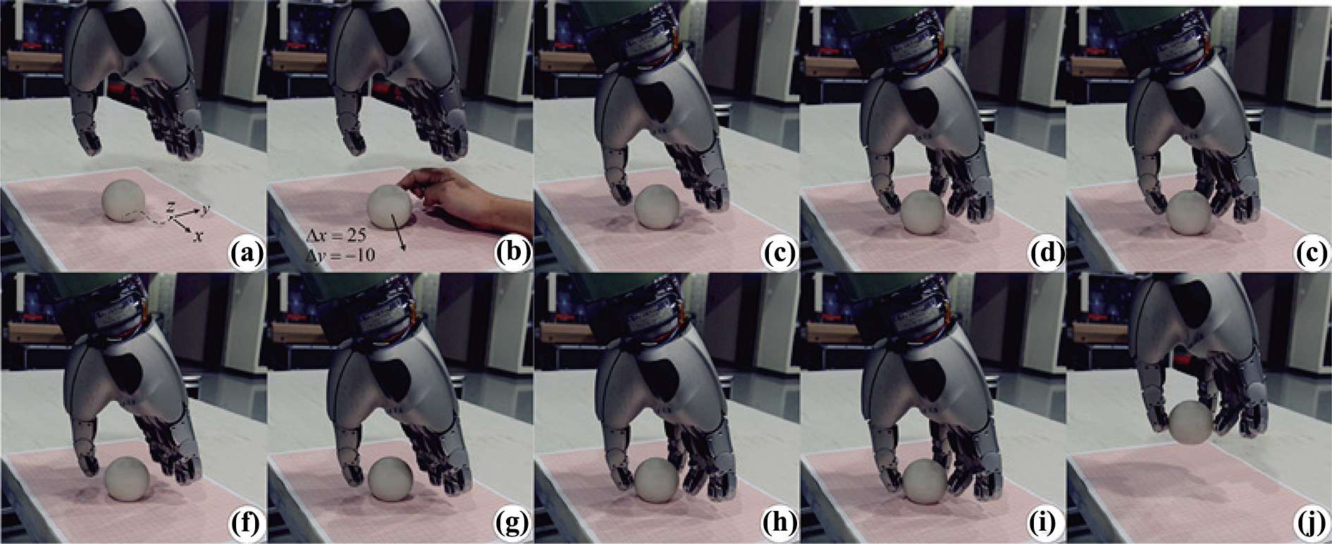
The process of grasping the ball by adaptive grasp strategy when Δx = 25 mm and Δy = −10 mm.
Then, the fingers return to the initial position, according to the object position error, the robot arm moves
For the long cylinder with h = 200 mm and Φ = 40 mm, when the position error direction is the same as the one that the hand approaching vector, the impact on the grasp stability is large, so a small error compensation range is set for the object separately, and
Figure 18 shows the progress of grasping cylinder by dexterous hand, the position errors are Δx = −12 mm, Δy = −10 mm, and

The process of grasping the cylinder by impedance control (Δx = −12 mm and Δy = −10 mm).
With the adaptive grasp method, the grasp process is shown in Figure 19. The thumb and the index finger contact the object and maintain contact (Figure 19(c)), followed by the middle finger and ring finger (Figure 19(d)). The estimated position error value of the object can be calculated by the tactile sensor

The process of grasping the cylinder by adaptive grasp strategy (Δx = −12 mm and Δy = −10 mm).
Finally, the building block in the experiment is taken as an example to explain the adjusting process for the posture error of the object. The building blocks are nonrotating, with the length, width, and height measuring 31, 62, and 100 mm, respectively, which are characterized by lightweight and small friction with the desktop. In the object coordinate system, the object is rotated by 30° relative to the object coordinate system and moves 5 mm and 5 mm along the x-axis and the y-axis, respectively. Figure 20 shows the grasp process of the finger directly using impedance control. When the finger starts to grasp, it can be seen that the middle finger slips out of the edge of the object after the contact, only two fingers contact with the object (Figure 20(c)), and the pose of the object is changed after the completion of grasp, which has been in unstable state actually (Figure 20(d)), so the object is dropped during the lift of arm, and the grasp fails (Figure 20(e)). It can be seen that the posture deviation has a great influence on the stability of the nonrotating body.

The process of grasping the building block by impedance control (Δx = −5 mm, Δy = 5 mm, and Δθ = 30°.
Figure 21 shows the process of grasping the blocks when the adaptive grasp method is used. Figure 22 shows the fingertip position, fingertip force, and state function in each finger coordinate system during the grasping process. At 1.2 and 1.5 s, the middle finger and the index finger contact with the object and switch the force control to maintain contact force. As the contact force is small, the middle finger does not slip,

The process of grasping the building block by adaptive grasp strategy (Δx = −5 mm, Δy = 5 mm, and Δθ = 30°.

(a) to (c) Fingertip positions, (d) forces, and (e) state function in finger coordinate when grasping by adaptive grasp strategy (Δx = −5 mm, Δy = 5 mm, and Δθ = 30°.
In addition, in the pose error results estimated by the grasp experiment, there is about 3 mm deviation in position and about 4° deviation in posture between the estimated error obtained by the pre-grasp and the actual pose error of the object due to the sensor error and the control precision. This error will cause the pose error still present when regrasping, but, by error compensation, the actual error has been greatly reduced, so only the force collaboration grasp method can guarantee stable grasp.
The results of the experiment for 15 kinds of objects are shown in Figure 23. For each object, the grasp is conducted for six times in the three error ranges respectively. When the position error is in
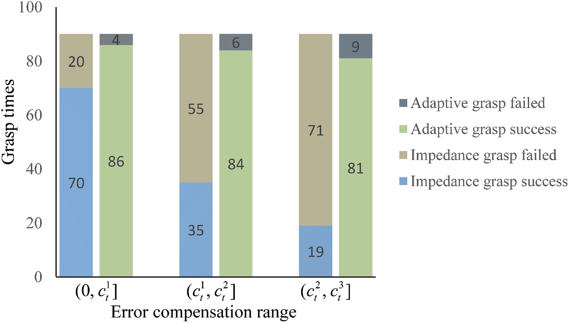
The results of grasp experiments.
Therefore, when the position error is in
Conclusions
In this article, an adaptive grasp strategy based on collaboration control and error estimation compensation is proposed for the influence of object pose uncertainty on grasp, by which the impedance control and force control are switched among different states of the finger to realize the process of the fingers contacting with the object one after another and, meanwhile, with the application of grasp force to ensure the stability of the object during the pre-grasp process. In the error compensation method, the pose error of the object is estimated and analyzed by finger tactile information in pre-grasp. Different methods are used to compensate for the pose error of the object according to different error ranges to reduce the impact of pose error of the object. The results show that the success rate of the object can be improved using the adaptive grasp method in the case of the uncertainty of the object pose.
Footnotes
Declaration of conflicting interests
The author(s) declared no potential conflicts of interest with respect to the research, authorship, and/or publication of this article.
Funding
The author(s) disclosed receipt of the following financial support for the research, authorship, and/or publication of this article: This work was supported in part by the Research Project of the State Key Laboratory of Mechanical System and Vibration (no. MSV201609), the Self-Planned Task of the State Key Laboratory of Robotics and System (no. SKLRS201612B), the National Natural Science Foundation of China (no. 61503095), the Foundation for Innovative Research Groups of the National Natural Science Foundation of China (no. 51521003), and the Fundamental Research Funds for the Central Universities (no. HIT.NSRIF.201640).