
Abstract
Three-dimensional object detection aims to produce a three-dimensional bounding box of an object at its full extent. Nowadays, three-dimensional object detection is mainly based on red green blue-depth (RGB-D) images. However, it remains an open problem because of the difficulty in labeling for three-dimensional training data. In this article, we present a novel three-dimensional object detection method based on two-dimensional object detection, which only takes a set of RGB images as input. First, aiming at the requirement of three-dimensional object detection and the low location accuracy of You Only Look Once, a modified two-dimensional object detection method based on You Only Look Once is proposed. Then, using a set of images from different visual angles, three-dimensional geometric data are reconstructed. In addition, making use of the modified You Only Look Once method, the two-dimensional object bounding boxes of the forward and side views are obtained. Finally, according to the transformation between the two-dimensional pixel coordinate and the three-dimensional space coordinate, the two-dimensional object bounding box is mapped onto the reconstructed three-dimensional scene to form the three-dimensional object box. Because this method only needs the collection of two-dimensional images to train the modified You Only Look Once model, it has a wide range of applications. The experimental results show that the modified You Only Look Once model can improve the location accuracy, and our algorithm can effectively realize the three-dimensional object detection without depth images.
Keywords
Introduction
Three-dimensional (3D) object detection predicts the category of an object along with 3D bounding box in scenes such as point clouds. In recent years, 3D object detection has been a focus of attention in both industry and the research community because of its extensive application in autonomous driving, face recognition, robotic navigation, and so on.
Most traditional methods rely on expensive light detection and ranging (LiDAR) systems, such as the Velodyne. 1,2 With the recent popularity of depth sensors such as Kinect, efforts are taken to replace the LiDAR systems with depth images for 3D object detection. Sliding shapes 3 extract 3D features from depth rendering for computer aided design (CAD) models, in order to train an exemplar-support vector machine (SVM) classifier. During testing time, the algorithm slides a 3D detection window in 3D space and applies SVM to directly classify each 3D window. However, the algorithm is very slow because of the use of hand-crafted features and many exemplar classifiers.
Some recently proposed methods 4 –6 apply deep learning technique to 3D object detection 4,5 and improve feature representation with convolutional neural networks. These networks project the 3D candidate box to the reference RGB-D image and generate two-dimensional (2D) proposals, which are fed to pretrained region proposal convolution neural networks (R-CNNs) to extract features for both RGB and depth channels. In addition, deep sliding shapes 6 propose the 3D region proposal network (RPN) to get 3D proposals at two scales with different receptive fields.
Although experiment results of these approaches are encouraging, there are also several challenges for 3D object detection based on RGB-D images. First, the 3D feature representation requires expensive computations. Second, 3D object bounding boxes vary in size more than 2D bounding boxes. Last but not least, the detector accuracy heavily depends on the sufficiency of training examples, 7 while labeling positive and negative examples is not an easy task compared with the 2D case.
Compared with 3D object detection, 2D image-based object detection has made great progress with deep convolutional networks. Girshick et al. 8 in their study proposed R-CNN. Compared with the traditional detection methods, R-CNN achieves excellent object detection accuracy, say about 63%. But it has a notable drawback of slow detection speed, requiring 47 s for each image. For fixing this shortcoming of R-CNN, Fast R-CNN 9 and Faster R-CNN 10 were successively proposed. Faster R-CNN 10 improves the detection speed, up to 7 fps. However, it still needs to generate region proposals, which is time-consuming in detection systems.
You Only Look Once (YOLO) 11 models object detection as a regression problem. It divides the input image into 7 × 7 grids and predicts two bounding boxes for each grid cell. Simultaneously, each grid cell predicts one set of class probabilities (including 20 classes), regardless of the number of boxes. YOLO processes images at 45 fps with the mean average precision (mAP) of 63.4%, but it makes more localization errors. Single Shot MultiBox Detector (SSD) 12 is the current state-of-the-art object detection system, which achieves an mAP of 72.1% on VOC 2007 test at 58 fps. But SSD performs poorly when detecting small objects. 13
At the same time, 3D reconstruction technology has been one of the most popular research fields of computer vision. With the development of the reconstruction method, it plays an important role in more and more fields. The 3D reconstruction based on sequence images is one of the mainstream reconstruction methods, including feature matching, camera calibration, 3D surface texture reconstruction, and other steps. Through the camera calibration, the mapping relationship between the 2D pixel image and the 3D space is obtained. Using the mapping relation, the spatial coordinates of the matching feature points can be obtained, and the sparse 3D point clouds of the object are generated.
Because of the success of 2D object detection and the mapping relationship between 2D images and 3D space, we present a 3D object detection method based on 2D object detection. Our work first parses over 2D images and then projects detection results from reference RGB images into 3D point clouds. In the practice application, many scenes contain small objects to be detected. In addition, the intersection over union (IOU) between the predicted box and the ground truth is very important for object detection. Considering these factors and the characteristics of YOLO, we will have some modifications on YOLO, and the new approach is named M-YOLO. Then, through the M-YOLO detection method, the 2D object bounding boxes are obtained in the forward and left views. Furthermore, using a set of images from different visual angles 3D geometric data are reconstructed. Finally, according to the transformation between the 2D pixel coordinate and the 3D coordinate, the 2D object bounding box is mapped onto the reconstructed 3D scene to form the 3D object box. This method only needs the collection of 2D images to train the M-YOLO model, and thus, it has a wide range of applications.
The main contents of this article are as follows. In the second section, the novel object detection method “M-YOLO” is described. In the third section, the principle of 3D object detection based on 2D object detection is introduced, followed by the experimental results of the new detection method in the final section.
M-YOLO
In this section, we introduce a modified object detection method, M-YOLO, to improve the positioning accuracy. Benefiting from the thoughts of “cluster center” in the super-pixel segmentation and “anchor box” in Faster R-CNN, we introduce novel bounding boxes, called cluster boxes, which can completely cover the whole image. Therefore, there is a smaller gap between the predicted box and the ground truth box than that of YOLO at the beginning of training. In addition, the method substitutes YOLO’s last fully connected layer with a convolutional layer, which generates category scores and box offsets for each cluster box. At the same time, the class-based non-max suppression (C-NMS) is designed, in order to solve the problem that the same object is identified as different categories. Compared with YOLO, M-YOLO improves the positioning accuracy while keeping the detection accuracy.
Principle of M-YOLO
The anchor box is first introduced in the Faster R-CNN. 10 Each feature point in the last convolutional layer of RPN is an anchor. For each anchor, nine kinds of anchor boxes can be pre-extracted using three different scales and three different aspect ratios (Figure 1). Compared with YOLO’s two predicted bounding boxes, the anchor boxes of Faster R-CNN take into account the objects with different scales and aspect ratios. Therefore, on the basis of YOLO, we prepare to increase the number of predicted borders with multiple scales and aspect ratios, in order to improve the positioning accuracy.

Anchor boxes of the Faster R-CNN. R-CNN: region proposal convolution neural networks.
Additionally, if the anchors in Faster R-CNN are mapped onto the original image, there are some evenly distributed feature points in the image. Inspired by this, we managed to directly select some evenly distributed points in the input image and take them as the center of predicted borders.
Super-pixel refers to an irregular pixel block with a certain visual representation, which consists of adjacent pixels with similar characteristics such as texture, color, brightness, and so on. 14 In simple linear iterative clustering (SLIC)-based super-pixel segmentation, the first step is to select orderly and evenly distributed points in the input image as the cluster centers. The cluster centers can be fine-tuned to avoid appearing on the boundary of different color blocks. Using cluster centers as the initial centers of the iterative algorithm, the super-pixel with cluster center can be obtained after several iterations (Figure 2). Because of the character of cluster centers, our method directly uses them as the center of predicted borders.

Cluster centers and super-pixel segmentation.
In the article, our approach selects n × n cluster centers in the original image. Then, at each cluster center, predict m bounding boxes with different scales and aspect ratios. The scale of the bounding boxes can be 1 × 1, 2 × 2, 4 × 4…, and the aspect ratios can be 1:1, 1:2, 2:1…. The sketch map of cluster boxes is shown in Figure 3; we use n = 7 and m = 9. The number of cluster centers and predicted boxes is an important parameter affecting the detection results. We increase the number of cluster centers, from 7 × 7 to the maximum 17 × 17, and the number of predicted bounding boxes, from 2 to the maximum 9 for each cluster center. The measure can improve the IOU performance.

The sketch map of cluster boxes.
On bounding box predictions, each grid cell of YOLO shares 20 classification information, because it only predicts two boxes and can only have one class. This constraint limits the number of nearby objects that the model can predict. In our method, all the boxes of each cluster center do not share 20 classification information, in order to detect nearby different objects.
M-YOLO substitutes YOLO’s last fully connected layer for a convolutional layer, on which the cluster boxes have stable sequences. Our method uses the cluster boxes as the references. The network generates category scores and box offsets for each cluster box. As cluster boxes are orderly and evenly distributed in the input image, the gap between the predicted box and the ground truth box is smaller than that of YOLO at the beginning of the training process. Thus, this model performs well when trained and benefits convergence speed. The mapping between the new convolutional layer and predicted boxes is shown in Figure 4.

Mapping between the new convolutional layer and predicted box of M-YOLO. M-YOLO: modified You Only Look Once model.
The object detection process of M-YOLO is shown in Figure 5. First, it selects n × n cluster centers in the original image and predicts m bounding boxes with different scales and aspect ratios at each cluster center. Then, the image is given as the input to CNN to predict confidence, class probabilities, and box offsets for each cluster box. Finally, NMS is used to eliminate redundant detections.

The object detection process of M-YOLO: (a) cluster center, (b) anchor box, (c) CNN, (d) bounding box, and (e) final detections. CNN: convolution neural networks; M-YOLO: modified You Only Look Once model.
Class non-max suppression
To detect different objects in a wide range of scales and aspect ratios, the nine bounding boxes of each cluster center do not share classification information. When testing with a trained model, there is a problem that the same object is identified as different categories by different bounding boxes. As shown in Figure 6(a), the object ‘person’ is identified as the person or bicycle. To solve this problem, we introduce the C-NMS. For all bounding boxes of adjacent cluster centers, if the class probability is greater than a certain probability score (we used 0.2) and the overlap degree between adjacent bounding boxes is greater than a threshold (we used 0.5), we believe that the same object is identified as different categories by redundant bounding boxes. Thus, only the bounding box having the largest area is chosen as the final object bounding box. Figure 6(b) is the result after using C-NMS.

The result after using C-NMS. The effect of C-NMS: (a)the detection result without C-NMS and (b)the detection result with C-NMS. C-NMS: Class non-max suppression.
Experimental validations
In this article, we train the network on the VOC 2007 train + VOC 2007 val + VOC 2012 train + VOC 2012 val data set, which consists of about 15 k images over 20 object categories. Throughout training, we use a batch size of 64, a momentum of 0.9, and a decay of 0.0005. Additionally, with the increase in iteration times, learning rate is constantly changing. Figure 7 shows the change in learning rate for M-YOLO, and the LR is 0.0005. To avoid model diverging, we start at a relatively small learning rate. After that we slowly raise the learning rate from LR to 10LR. We continue training with 10LR for 14,000 iterations, then LR for 10,000 iterations, and finally 0.1LR for 10,000 iterations.

The change of learning rate.
In our model, we need to determine two parameters: the number of cluster centers (n) and that of bounding boxes for each cluster center (m). The number of cluster centers changes from 7 × 7 to 17 × 17. The bounding boxes are set according to the setting rules of anchor boxes in Faster R-CNN. Simultaneously, in view of YOLO’s two boxes and Faster R-CNN’s nine boxes, we also set the number of bounding boxes to five for comparison. We evaluate it on the VOC 2007 test data set consisting of about 5 k images. Performance metrics include the mAP, the recall rate (R), and the IOU. We also compare with YOLO on the VOC 2007.
As presented in Table 1, the model M-YOLO-15-5 (m = 15, n = 5) achieves the highest detection quality with an mPA of 61.07% in all models, and it is slightly higher than YOLO. The model M-YOLO-17-9 (m = 17, n = 9) has the highest IOU (79.99%). Compared with YOLO, it improves IOU about 10% and has more accurate object bounding boxes. Moreover, M-YOLO-17-9 also pushes the recall rate to 89.95%, which is 13% more than that of YOLO. Simultaneously, we can see that the IOU and recall rate tend to be stable as the cluster center number increases as well as the value of nine bounding boxes is higher than that of five bounding boxes in general.
PASCAL VOC2007 test detection results.

mAP: mean average precision; IOU: intersection over union; YOLO: You Only Look Once; M-YOLO: modified You Only Look Once method. Boldface value: the best result.
Because our ultimate aim is to generate 3D object detection, both mAP and IOU are considered as key elements. Based on the comprehensive consideration, we chose the M-YOLO-15-9 model for 2D object detection.
3D object detection
Our 3D object detection method is based on 2D object detection. Figure 8 shows the pipeline of 3D object detection. First, reconstruct 3D geometric data using a set of images from different visual angles. Then, through M-YOLO, the 2D object bounding boxes of he forward and side views are obtained. In addition, determine the depth of the 2D object bounding box in 3D space based on the shortest 3D Euclidean distance. Finally, according to the transformation between the 2D pixel coordinate and the 3D coordinate, the 2D object bounding box is mapped onto the reconstructed 3D scene to form the 3D object box. At the same time, aiming at the problem that the 3D object bounding box has some angle difference with the object, correct the 3D bounding box using coordinate rotation and translation.

The pipeline of 3D object detection.
Multiview reconstruction environment
3D reconstruction is the first step of our 3D object detection method. In this article, we use the multiview environment (MVE) 15 for multiview geometry reconstruction. The system takes a set of photographs as input and produces a surface triangle mesh of the scene as output. The system covers structure-from-motion (SfM), multiview stereo (MVS), and surface reconstruction.
First, SfM reconstructs the parameters of cameras by finding sparse correspondences in the images. The recovered camera parameters consist of the extrinsic camera parameters (position and orientation) and the camera calibration data (focal length and radial distortion). Meanwhile, sparse 3D point clouds are created as a by-product of camera reconstruction. Then, MVS reconstructs dense 3D geometry by finding visual correspondences in the images using the estimated camera parameters. Finally, surface reconstruction takes as input dense point clouds and produces a globally consistent surface mesh. Figure 9 shows the 3D reconstruction result, with the top row showing 6 of 14 input images and the bottom row showing the reconstruction stereo images.

The 3D reconstruction result based on the sequence of image. 3D: three-dimensional.
3D object bounding box
Basic equation
The camera imaging geometry is shown in Figure 10. Let’s denote the 2D point by

where s is an arbitrary scale factor; (
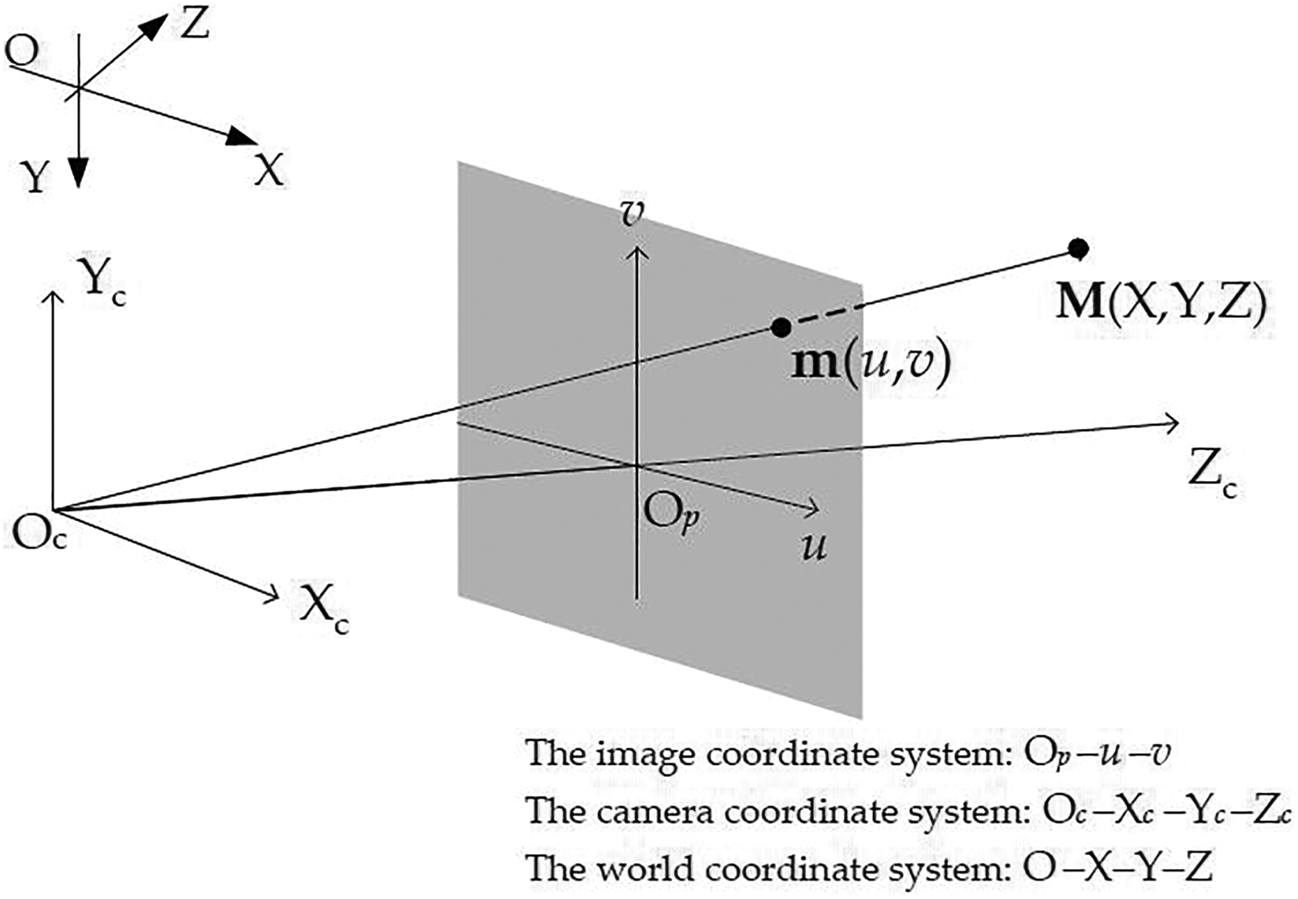
The camera imaging geometry.
Let’s denote the ith column of the rotation matrix
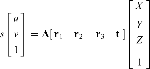

Given the camera parameters and the 2D point

where X −1 denotes the inverse matrix of X. Note that according to different coordinate Z, the 2D point can have different 3D projected points. However, these 3D points are on the same ray.
Forming 3D object bounding box
In our approach, the formation of the 3D object box requires first obtaining the depth of the 2D object bounding box in 3D space. In MVE, reconstructed 3D points are denoted by the world coordinate [X, Y, Z]T, so we regard coordinate Z as the depth of 3D point in the stereo image. In addition, the parameters of camera can be reconstructed by SfM techniques. Based on the camera parameters and 2D point coordinates, we can generate a projection ray in the reconstructed stereo images. Therefore, the method based on the shortest 3D Euclidean distance is proposed to determine the depth of the front and back views. The 3D Euclidean distance is

First, the 2D object bounding boxes of the forward and side views are obtained using M-YOLO. Then, project the central point of the 2D object box, from the forward view into the reconstructed 3D image, to form the projection ray. Finally, on the ray, seek the 3D point that has the shortest Euclidean distance with the reconstructed point clouds; and this 3D point is the projection point for the central point of the 2D object box, denoted by

The schematic diagram for obtaining the depth of front and back views.
According to the two depth information and equation (3), we can project the 2D object box of the forward view into the 3D image, forming the front and back bounding boxes of the 3D object. Then, the corresponding vertices of two bounding boxes are connected to form the final 3D object bounding box. Figure 12 is the forming process of 3D object bounding box.
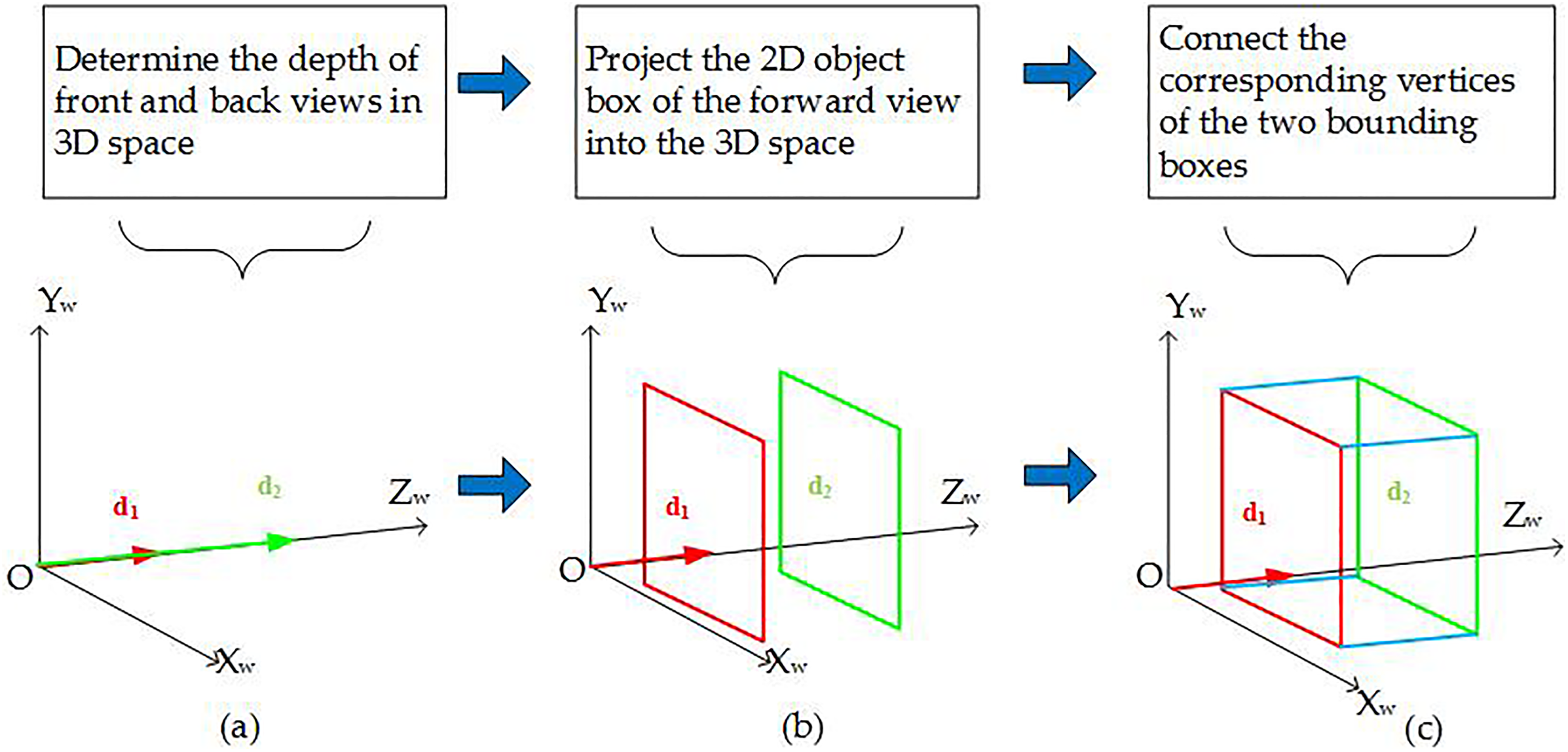
The forming process of the 3D object bounding box. 3D: three-dimensional.
Correction of 3D object bounding box
The 2D object box of the forward view is mapped onto the 3D image by two fixed depths (

where (

The 3D object bounding box before and after correction. 3D: three-dimensional.
Experimental results
Our experimental environment is Ubuntu. In Figure 14, we demonstrate in a practical walk-through of 3D object detection for a car. Starting from input images, the MVE is used to reconstruct the stereo image (Figure 14(a)). 2D object bounding boxes are obtained using M-YOLO (Figure 14(b)). Then, according to the 2D bounding boxes and camera parameters, 3D object bounding box is generated (Figure 14(c)). Finally, correct the 3D bounding box using coordinate rotation and translation (Figure 14(d)).

The practical walk-through of 3D object detection. 3D: three-dimensional.
Figure 15 shows the ground truth and predicted box of car. Information of the 3D predicted box and 3D ground truth is presented in Table 3. The (x, y) coordinates represent the center of the box relative to the cluster boxes in the 2D image. The width and height are predicted relative to the whole 2D image. The (


The ground truth and predicted box of a car.
The algorithm for obtaining the depth of front and back views.

3D: three-dimensional.
Information of the 3D predicted box and 3D ground truth.
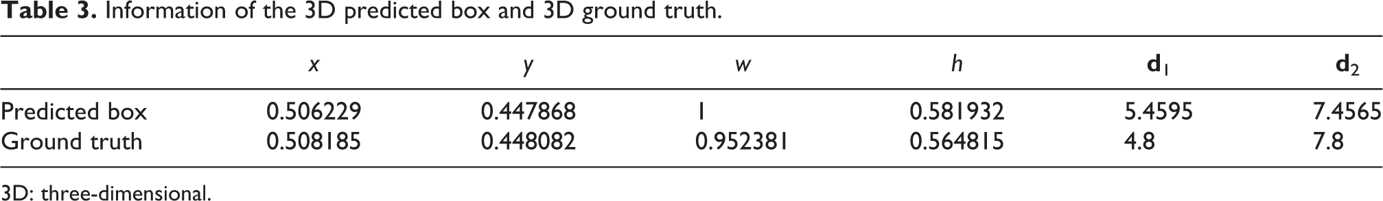
3D: three-dimensional.
Figure 16 shows the detection results for the person or bicycle. As we can see, our algorithm can effectively realize the 3D object detection, but its IOU3D still needs to be improved. Figure 17 shows the comparison of detection results of different algorithms. It can be seen that these methods have similar detection effects.

The detection results of the person and bicycle.

The comparison of detection results for different algorithms.
Our 3D object detection method takes a set of multiangle RGB images as input, without using depth images. However, the performance comparison of 3D object detection methods in the studies by Song and Xiao 3,6 and Chen et al. 4 is based on the same depth image database, which is not applicable to our method. Therefore, our method cannot be quantitatively compared with other methods.
Conclusion
In this article, we design a method to obtain the 3D object bounding box based on M-YOLO. The experimental results show that M-YOLO can improve the accuracy of the 2D object box, and the 3D object detection method can realize the 3D object detection without depth images. The final result shows that the detection method is effective.
Footnotes
Declaration of conflicting interests
The author(s) declared no potential conflicts of interest with respect to the research, authorship, and/or publication of this article.
Funding
The author(s) disclosed receipt of the following financial support for the research, authorship, and/or publication of this article: Shanghai Aerospace Science and Technology Innovation Fund: Research on Image Matching and Spatial Object Recognition Based on Depth Learning (SAST2016018)