
Abstract
Road obstacle detection is an important component of the advanced driver assistance system, and to improve the speed and accuracy of road obstacle detection method is a vital task. In this article, fast image region-matching method based on the maximally stable extremal regions method is proposed to improve the speed of image matching. The theoretical feasibility of detection method combining monocular camera with inertial measurement unit (IMU) is clarified. The fast road obstacle detection method based on maximally stable extremal regions combining fast image region-matching method based on maximally stable extremal regions and the vision-IMU-based obstacle detection method is proposed to bypass obstacle classification and to reduce time and space complexity for road environment perception. The AdaBoost cascade detector, the speeded-up robust features-based obstacle detection method, and the proposed method are used to detect obstacles in outdoor contrast tests. Test results show that the proposed method has higher accuracy, and the reason of high accuracy is analyzed. The processing time of AdaBoost cascade detector, speeded-up robust features-based obstacle detection method, and proposed method are compared, and the results show that the proposed method has faster processing speed, and the reason of faster processing speed is analyzed.
Introduction
Road obstacle detection is an important component of the advanced driver assistance system and has attracted an extensive amount of interest from both academia and automobile industry. Although LiDAR and millimeter wave radar have higher robustness and accuracy, the cost has restricted their application in road obstacle detection. Machine vision has been paid more attention to and has been studied deeply in the aspect of road obstacle detection because of meeting the human visual cognitive habit and low cost. With the development of artificial intelligence, machine learning algorithm has been gradually introduced into the obstacle detection method to improve the accuracy. Pomerleau applied artificial neural network to the identification of traffic environment. 1 Xiao et al. used random forest method to obtain better results in structured road detection. 2 Sivaraman et al. proposed an active learning framework based on Haar features and adaptive boosting algorithm (AdaBoost) 3 to detect vehicles in high way environment. Song et al. improved the robustness and real time of vehicle detection through the integration of AdaBoost and convolutional neural network (CNN). 4 The continuous development of generative adversarial networks, SegNet, Faster-CNN, and other new concept of machine learning increases the potential for improving the accuracy of monocular obstacle detection. 5 –7 Obstacle detection methods above are based on accurate classification of obstacles, and accurate classification requires large amount of samples and high computational cost. In sparse optical flow field-based obstacle detection methods 8 –11 and motion compensation-based obstacle detection methods, 12 –14 lots of feature points must be extracted by Harris corner detector, 15 scale-invariant feature transform (SIFT),, 16,17 speeded-up robust features (SURF), 18 –20 features from accelerated segment test, 21,22 or other traditional feature point detectors. In traditional feature point detectors, feature points are determined by detecting local feature of every pixel in the images, thus leading to a large number of feature points. The processing and analysis of large numbers of feature points increases the computational cost of road obstacle detection, and road obstacle detection speed is influenced.
Road obstacles in two-dimensional (2D) images can be described by regions, the number of regions is less than feature points, and the regions can be easily tracked if they are stable. The maximally stable extremal regions (MSER) method denotes a set of distinguished regions that are detected in a grayscale image. All of these regions are defined by an extremal property of the intensity function in the region and on its outer boundary. MSERs have properties that form their superior performance as stable local detector. 23,24 Thus, we propose a fast road obstacle detection method based on MSER to speed up obstacle detection using improved MSER region-matching method and pinhole camera model.
Feature points are determined by detecting local feature of every pixel in the images for traditional feature point detectors, thus leading to a large number of feature points, and the huge number of feature points increases the computational cost of road obstacle detection and road obstacle detection speed is influenced. Small amount of feature points can be extracted by MSER-based image region-matching method. However, clustering method and pattern recognition method cannot be used if there are few feature points. Therefore, the fast road obstacle detection method based on MSER combining fast image region-matching method based on MSER and the vision-inertial measurement unit (IMU)-based obstacle detection method is proposed to bypass obstacle classification and to reduce time and space complexity for road environment perception.
In this article, a fast region-matching method based on MSER is proposed to speed up MSERs’ matching, and this method is presented in the “Fast image region-matching method based on MSER” section. Monocular camera- and IMU based obstacle detection method (also called the vision-IMU-based obstacle detection method) is presented in the “Vision-IMU-based obstacle detection method” section. The fast road obstacle detection method based on MSER combining the fast region-matching method and the vision-IMU-based obstacle detection method is presented in the “Fast road obstacle detection method based on MSER” section. Effect analysis of fast road obstacle detection method based on MSER and conclusions of this article are presented in the “Effect analysis of fast road obstacle detection method based on MSER” and “Conclusion” sections, respectively.
Fast image region-matching method based on MSER
The MSER algorithm is widely used in image registration and region matching. 25 –31 In most MSER-based image region matching, first, MSERs are extracted by MSER extraction algorithm firstly, and all MSERs in the reference image and the target image are fitted into elliptical regions to provide more useful information secondly, and feature point detection methods, such as SIFT and affine-SIFT (ASIFT), are used to improve matching precision finally. In the process of road obstacle detection, if images are collected at a short time interval, the position and area shape of MSERs in the two images will not change greatly, and affine change will not be obvious. Therefore, we propose a fast image region-matching method using the stability of MSERs and ignoring MSERs’ position and shape difference between two images, to simplify matching process and to improve matching speed. Process of fast image region-matching method based on MSER is as follows and is shown in Figure 1:
MSER extraction. Extract maximally stable extremal regions using traditional MSER method.
32
Area calculation. Let Ab ( Distance calculation. Let Cb( Image region matching. Let Mi be match value set of the i th MSER, and the MSER corresponding to the minimum Mi is considered as the matching region.


Schematic diagram of fast image region-matching method based on MSER. MSER: maximally stable extremal regions.
Vision-IMU-based obstacle detection method
Small amount of feature points can be extracted by MSER-based image region-matching method. Clustering method and pattern recognition method cannot be used to detect obstacles. Therefore, the vision-IMU-based method is used to detect obstacle directly and accurately.
Static obstacle detection
Image acquisition is the process of mapping objects in 3D space to 2D image plane, and this process can be simplified as a pinhole camera model (see Figure 2). The effective focal length of the camera is f, the installation height of the camera is h, and the pitch angle of the camera is ∂. The coordinate origin of the plane coordinate system


Schematic diagram of pinhole camera model.
The first imaging point of obstacle is A (see Figure 3), y axis is moved from y1 to y2 in the image plane because of the camera’s movement, and the imaging point of obstacle’s top is B. Assuming that A is the imaging point of A′ on the road plane and B is the imaging point of B′ on the road plane, then the horizontal distance from the camera to A′ is d1 and the horizontal distance from the camera to B′ is d2. d1 and d2 can be calculated by equation (1), and the relationship is

Schematic diagram of static obstacle imaging.
Moving obstacle detection
When the front obstacle moves along the horizontal direction (see Figure 4), the distance from camera to obstacle’s top point at the previous moment is s1, the distance from camera to obstacle’s top point at the following moment is s2, and the relationship between d1, d2, s1, and s2 is

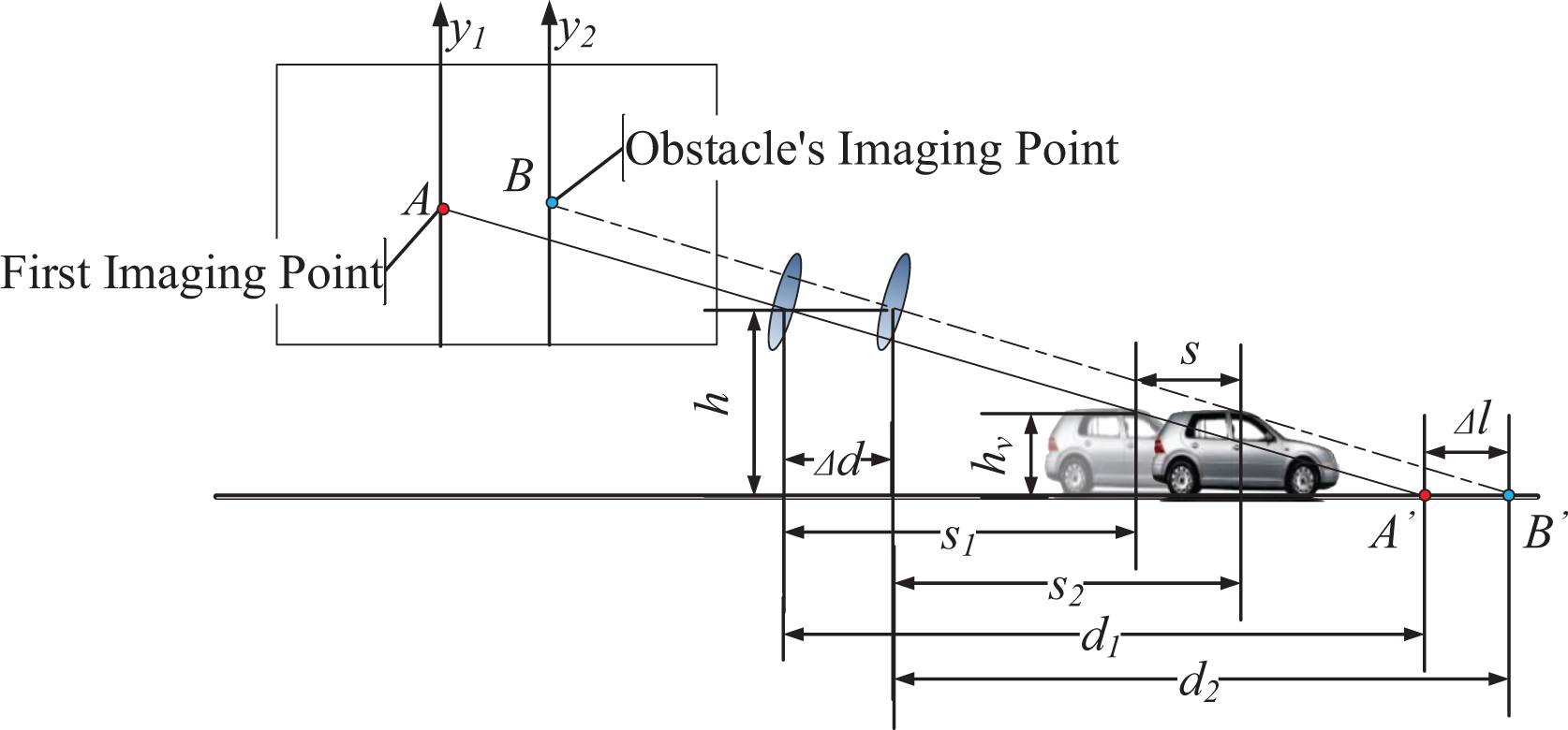
Schematic diagram of moving obstacle imaging.
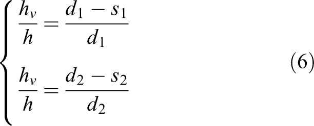
The relationship between hv, h, d1, d2, s1, and s2 according to the characteristic of right triangle is
Δl can be calculated according to equations (2) and (3) as
Fast road obstacle detection method based on MSER
Fast road obstacle detection method based on MSER is proposed by combining fast image region-matching method based on MSER and vision-IMU-based obstacle detection method. The fast image region-matching method based on MSER is used to simplify matching process and to improve matching speed, and the vision-IMU-based obstacle detection method is used to detect obstacles using less feature points.
Process of fast road obstacle detection method based on MSER
Process of the fast road obstacle detection method based on MSER is as follows and is shown in Figure 5.

Fast road obstacle detection method based on MSER. MSER: maximally stable extremal regions.
Camera parameter updating based on IMU data
Calibration of camera initial parameters. Calibrate the monocular camera mounted on the vehicle and get the camera focal length f, the mounting height h, the pitch angle ∂, and the pixel size of the photosensitive chip p. Continuous inertial data acquisition. At the beginning of t = 0, continuously acquire inertial data by IMU rigidly connected with monocular camera with frequency F. Camera parameters updating. Calculate Δd in period Δt according to inertial data.
Image region matching and obstacle detection
Image region matching based on MSER. Acquire road image at t and t + Δt and match image regions on the basis of MSER. Feature points position. Find centroids of matched regions as feature points. Horizontal distance calculation and obstacle detection. Assuming feature points are at the horizontal plane, calculate horizontal distance d1 from feature points to the camera at t; assuming feature points are at the horizontal plane, calculate horizontal distance d2 from feature points to the camera at t + Δt; compare Δl (
Obstacle detection experiment
OV5640 camera unit (OmniVision Technologies, Inc.) and JY61p IMU (Wit Motion Intelligent Technology Co., Ltd.) are mounted on a movable platform (see Figure 6 (a)). The obstacle is simulated by vehicle scaling model (see Figure 6 (b)). Traffic mark, road repair patches, and other visually significant non-obstacles are simulated by pieces of paper attached to the plane (see Figure 6 (c)). One of the indoor obstacle experiments is processed as follows.

Indoor experiment equipment. (a) Movable platform, camera unit, and IMU. (b) Vehicle scaling model (obstacle). (c) Traffic mark and road patch. IMU: inertial measurement unit.
Effective focal length of the camera f = 6.779 mm, installation height of the camera h = 6.572 cm, pitch angle of the camera ∂ = 0.132 rad, and pixel size of the photosensitive chip p = 1.4 µm.
The angular acceleration and acceleration data are acquired by the IMU with F = 100 Hz. The camera pose is solved using the quaternion method, and the pitch angle of the camera ∂ is updated. The horizontal distance Δd = 2.00 cm in period Δt = 2 s is calculated using acceleration data.
As mentioned in the third step of image region matching and obstacle detection in the “Process of fast road obstacle detection method based on MSER” subsection, t represents the moment of acquiring image data. The images at t = 0 and t = 2 are processed by fast image region-matching method based on MSER. Fourteen centroids of matched regions are found as feature points. The extraction of MSERs is shown in Figure 7, and the feature points are shown in Figure 8.

MSER extraction. (a) Image at t = 0. (b) Image at t = 2. (c) Matched images. Red regions and o are MSERs and centroids of MSERs in the image at t = 0, cyan regions, and + are MSERs and centroids of MSERs in the image at t = 2. MSER: maximally stable extremal regions.

Feature points. (a) Feature points in the image at t = 0. (b) Feature points in the image at t = 2.
Assuming feature points are at the horizontal plane, calculate horizontal distance d1 from feature points to the camera at t = 0; assuming feature points are at the horizontal plane, calculate horizontal distance d2 from feature points to the camera at t = 2; Δl and k (k = 2 cm) are compared to confirm obstacles. Calculation results of d 1, d 2, and Δl are shown in Table 1.
Calculation results of d 1, d 2, and Δl.

Calculation results show that feature points 6, 7, 8, and 9 are not at horizontal plane, and corresponding MSERs are considered as regions belonging to obstacles.
MSERs belonging to obstacles are labeled as obstacle region. The bottom of the obstacle region is considered as the intersection of the obstacle and the road, and the distance from obstacles to camera is calculated by pinhole camera model (see Figure 9).

Obstacle region. Yellow box is the detected obstacle region, and cyan box shows the distance from obstacle to camera.
Effect analysis of fast road obstacle detection method based on MSER
AdaBoost cascade detection method is a typical machine learning method, and it is widely used in obstacle because of its high accuracy and speed in target recognition. 33 –36 In contrast tests, a 20-level AdaBoost cascade detector using the Histogram of Oriented Gradient (HOG) feature is built, and the maximum false detection rate for each level of the cascade detector is 0.2. The car image data set of Stanford University Krause and pedestrian image data set of Center for Biological & Computational Learning at Massachusetts Institute of Technology (MIT CBCL) are artificially labeled, and the labeled regions are taken as the positive samples. The Pasadena_Houses_2000 image data set of the computer vision research group of California Institute of Technology is selected to provide negative samples. AdaBoost cascade detector (also called AdaBoost method) is trained using the positive and negative samples.
The SURF-based detector is several times faster than SIFT and is more robust against different image transformations than SIFT. 37 In contrast tests, the SURF is used to detect feature points in motion compensation-based road obstacle detection method. In SURF-based detection method (hereafter, SURF method) and fast road obstacle detection method based on MSER (hereafter, MSER method), if feature points or regions are detected as obstacle region and the points or regions close to each other, they will be classified as one obstacle.
The traffic environment on campus road is recorded by OV2710 camera unit, camera pose data is recorded by HEC295 IMU, and the image data and camera pose data are processed using the AdaBoost method, SURF-based detection method, and MSER method. The results are compared to analyze the accuracy and detection speed of the above three methods.
Analysis of detection accuracy
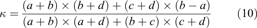
Producer’s accuracy (PA), user’s accuracy (UA), overall accuracy (OA), and κ are widely used in the field of remote sensing and pattern recognition because of high universality. 38 –40 PA, UA, OA, and κ are thus used as the evaluation indexes.
The number of pixels that are detected as obstacles by detection method but actually are not obstacles is ai. The number of pixels that are detected as obstacles and actually are obstacles is bi. The number of pixels that are not detected as obstacles by detection method but actually are obstacles is ci. The number of pixels that are not detected as obstacles by detection method and actually are not obstacles is di. Confusion matrix of detection results is shown in Table 2.

PA can be calculated as

UA can be calculated as

OA can be calculated as

κ can be calculated as
Confusion matrix of detection result.

Confusion matrix of AdaBoost method-detected results is shown in Table 3. Confusion matrix of SURF method-detected results is shown in Table 4. Confusion matrix of MSER method-detected results is shown in Table 5. Comparison of detection accuracy is shown in Table 6 and Figure 10. The obstacle detection results are shown in Figure 11.
Confusion matrix of AdaBoost method detected results.

Confusion matrix of SURF method detected results.

SURF: speeded-up robust features.
Confusion matrix of MSER method detected results.

MSER: maximally stable extremal regions.
Comparison of detection accuracy.

PA: producer’s accuracy; UA: user’s accuracy; OA: overall accuracy; SURF: speeded-up robust features; MSER: maximally stable extremal regions.

Histogram of detection accuracy.

Obstacle detection results. (a) Result of AdaBoost method. (b) Result of MSER method. The AdaBoost method did not detect the temporary traffic lights. MSER: maximally stable extremal regions.
It can be seen in Table 6 and Figure 10 that the PA of MSER method is lower than that of SURF method, and the UA of MSER method is higher than that of SURF method. That is because in complicated traffic environment, some obstacles are far from the camera or moving rapidly, and these obstacle regions may not be detected as stable regions by MSER.
It is also shown that the accuracy indexes of MSER method and SURF methods are higher than those of AdaBoost method in vehicle obstacle detection. The essence of AdaBoost method is bias classification, its accuracy is affected by the quality and quantity of training samples, and the accuracy of AdaBoost method is thus reduced. In addition, an AdaBoost method can only detect the trained targets, and if obstacles in test are not vehicles or pedestrians, AdaBoost method will not detect obstacles effectively.
Analysis of detection speed
Data of images and camera poses before and after moving should be processed in the SURF method and the MSER method, and all the time needed for detecting obstacles in an image is counted to compare detection speeds of the three methods. The average detection time of three detection methods is shown in Table 7.
Average detection time of three methods.

SURF: speeded-up robust features; MSER: maximally stable extremal regions.
It can be seen in Table 7 that the speed of AdaBoost method is faster than that of the SURF and MSER methods. That is because the AdaBoost method is trained using large amount of positive and negative samples and if the time of detector training is counted, the detection speed will be slower.
The speed of MSER method is faster than the SURF method because in MSER method, the processes of elliptical region fitting and feature point detected by SIFT or ASIFT are omitted. What’s more, MSER method detect region feature instead of local feature of every pixel in the image; thus, less number of stable feature points can be detected. Less points cause less calculation and faster obstacle detection speed.
Conclusion
In this article, fast image region-matching method based on MSER is proposed. In the fast image region-matching method, the processes of elliptical region fitting and feature point detecting by SIFT or ASIFT are omitted to improve the speed of image matching. The theoretical feasibility of detection method combining monocular camera with IMU is clarified through deriving horizontal distances from camera to static obstacle and moving obstacle. The fast road obstacle detection method based on MSER combining fast image region-matching method based on MSER and the vision-IMU-based obstacle detection method is proposed to bypass obstacle classification and to reduce time and space complexity for road environment perception.
Obstacle detection steps and indoor experiments are shown to expound the detection process of the fast road obstacle detection method based on MSER. The AdaBoost cascade detector, SURF-based obstacle detection method, and the proposed method are used to detect obstacles in outdoor contrast tests, and the PA, UA, OA, and κ are used as evaluating indexes to compare test results. The results show that the proposed method has higher accuracy, and the reason of high accuracy is analyzed. The processing time of AdaBoost cascade detector, SURF-based obstacle detection method, and proposed method are compared; the results show that the proposed method has faster processing speed, and the reason of faster processing speed is analyzed.
Footnotes
Declaration of conflicting interests
The author(s) declared no potential conflicts of interest with respect to the research, authorship, and/or publication of this article.
Funding
The author(s) disclosed receipt of the following financial support for the research, authorship, and/or publication of this article: This research is supported by the National Key Research and Development Program of China (2016YFD0701101), the Scientific Research Initial Foundation of Shandong University of Technology (4041416053), the National Natural Science Foundation of China (51508315), and the Natural Science Foundation of Shandong Province (ZR2016EL19).