
Abstract
In order to improve the kinematic reliability, it is crucial to find out the influence of each error source on the kinematic reliability of the mechanism. Reliability sensitivity analysis is used to find the changing rate in the probability of reliability in relation to the changes in distribution parameters. Based on the structural response surface function method, the functional relation between the kinematic reliability of a modified Delta parallel mechanism and the original input-error vectors is described using the quadratic function with cross terms. Moreover, the partial derivatives of the functional relation with respect to the means and variances of the original input errors are derived, which can efficiently evaluate kinematic reliability sensitivity of the mechanism. The advantages of this method are as follows: First, the response surface function, which can be easily set up by the position-error model of the mechanism, is convenient for calculating the variance, partial derivative, and reliability sensitivity. Second, in this case (unlike in the traditional error-mapping model), although the input-error values are unknown, pseudorandom variables used as random input-error sources can be generated by MATLAB software. Furthermore, the kinematic reliability of the mechanism can be assessed using the Monte Carlo method.
Keywords
Introduction
The Delta parallel mechanism was presented by Clavel 1 in 1988, as a high-speed parallel mechanism with three degrees of freedom (3-DOF). Currently, it is one of the most successful parallel mechanisms for commercial applications. However, it has the drawback of possessing several spherical joints, which are difficult to assemble and whose accuracy is difficult to guarantee. Tsai 2 –4 invented a modified 3-DOF Delta parallel mechanism. Its most important properties are that all the kinematic joints are rotational joints and that it provides large workspace, high stiffness, low inertia, and large payload capacity.
Kinematic reliability is defined as the probability that the end effector position and orientation fall within a specified range of the desired location. Because of geometric errors in the components of the mechanism, as well as the position and pose errors of the joints, the end effector position of the mechanism will deviate from the ideal kinematic trajectory, thereby reducing the mechanism’s kinematic accuracy. 5,6 Therefore, it is particularly important to determine whether the mechanism can accurately complete the specified motion by analyzing the kinematic reliability of this mechanism. The degree of influence of the errors on this kinematic reliability can be analyzed by means of kinematic reliability sensitivity analysis. 7 –16 At present, studies on reliability sensitivity analysis mainly focus on the structural system of the mechanism. Reliability sensitivity analysis research on the kinematic system of the mechanism is limited, and breakthroughs have been scarce. 17,18
This study aims to establish a kinematic-error model and analyze the kinematic reliability and reliability sensitivity of the modified Delta parallel mechanism, thus providing theoretical support for the design of such high-precision mechanisms.
Descriptions of the modified Delta parallel mechanism
The modified Delta parallel mechanism is shown in Figure 1.

Modified Delta mechanism.
The mechanism comprises a moving platform connected to a fixed platform by three parallel kinematic chains. Each chain contains a rotational joint activated by actuators on the fixed platform. The motion is transmitted to the moving platform through parallelograms formed by follower links and rotational joints, as shown in Figure 2.

Descriptions of the kinematic chain.
The end effector of the mechanism is installed at the center of the moving platform; its coordinates are expressed as [x, y, z]. The rotational joints at points Bi and Di (i =1, 2, 3) are placed in accordance with the equilateral triangle on the fixed and moving platforms.
The global coordinate system O-xyz is located at the center (point O) of the fixed platform. The xz plane coincides with the plane of the fixed platform, and the x-axis points to the center of the joint at point B 1 and the y-axis points vertically upward, as shown in Figure 3.
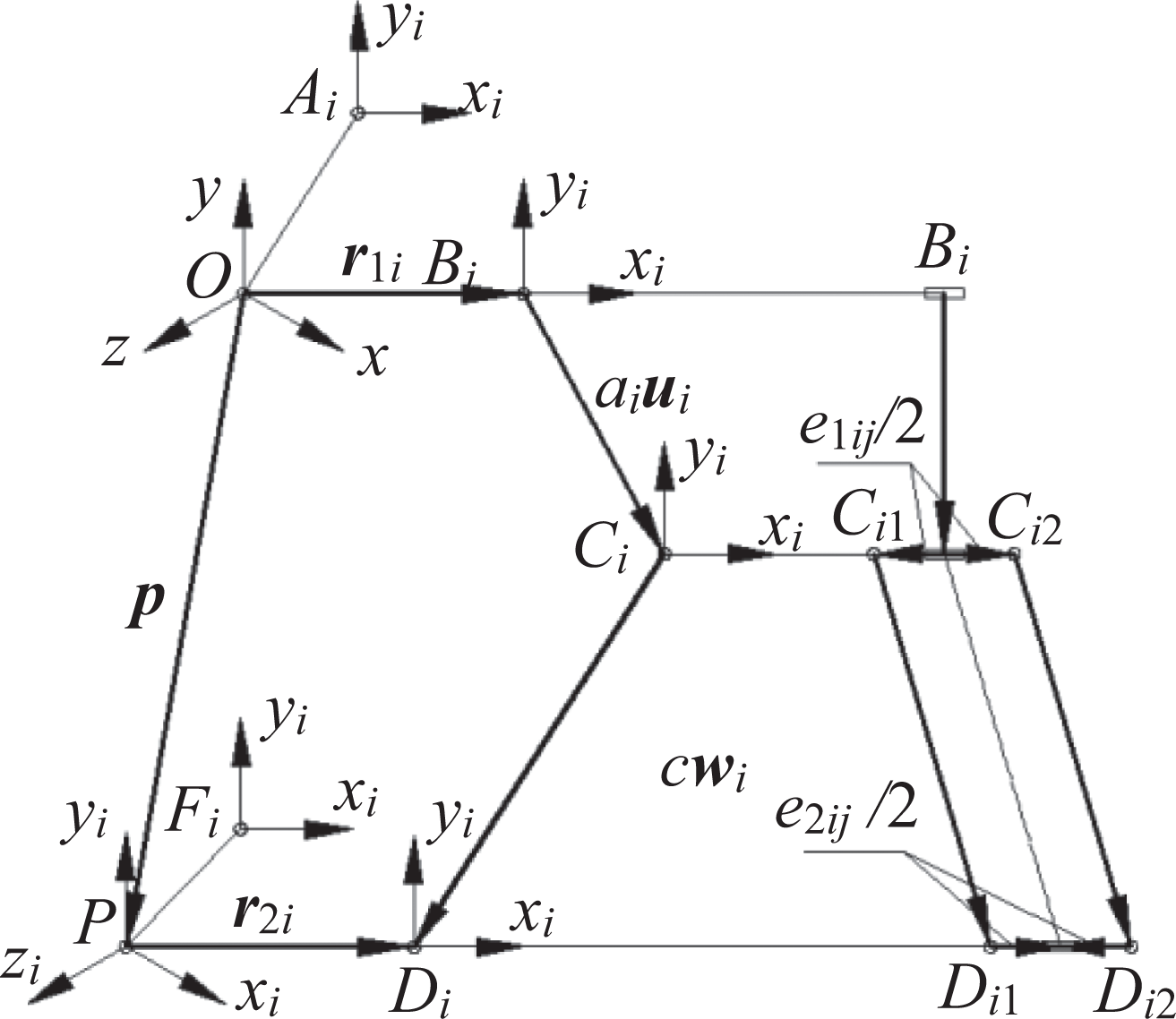
Coordinate system of the kinematic chain.
The reference coordinate system, Ai -xiyizi (i = 1, 2, 3), is obtained when O-xyz revolves by an angle βi (i = 1, 2, 3) around the y-axis, where βi is 0°, 120°, or 240°, respectively.
The body-fitted coordinate system Bi -xiyizi , Ci -xiyizi , and Di -xiyizi are located at points Bi , Ci , and Di , respectively. Their zi -axes coincide with the axes of the joints Bi , Ci , and Di , and their yi -axes point vertically upward.
The body-fitted coordinate system of the moving platform is given by P-xiyizi , whose xizi plane coincides with that of the moving platform and whose xi -axis points to the center of joint D 1 and the yi -axis points vertically upward. The reference coordinate system, Fi -xiyizi (i = 1, 2, 3), is obtained when P-xiyizi revolves βi along the yi -axis.
Kinematic-error model of the mechanism
According to Figure 3, a closed loop equation can be written for each chain

Rewriting equation (1) in the O-xyz coordinate frame leads to
where
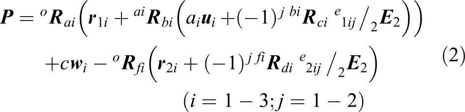
Under small perturbations, the position of the end effector can be expressed as

where
To obtain the position-error vectors Δ
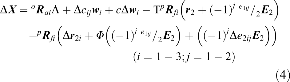
where
To eliminate the unit pose-error vector of the follower link, we multiply both sides of equation (4) by

where Δ
Subtracting equation (5) at j = 2 from equation (5) at j = 1 leads to

where Δcid = Δci 2 − Δci 1.
Simplifying equation (6), the pose-error mapping model of the mechanism can be constructed as

where
Adding equation (5) at j = 2 and equation (5) at j = 1 leads to

where ΔcPi = (Δci 2 + Δci 1)/2.
Substituting

where
Equations (7) and (9) show that 21 geometric errors affect the position and pose precision of the end effector, 9 geometric errors only affect the position precision of the end effector.
Kinematic reliability analysis of the mechanism using the Monte Carlo method
The Monte Carlo method is a numerical calculation method used to find an approximate solution to technical engineering problems by generating random statistical sampling data using a computer.
The process of evaluating kinematic reliability using the Monte Carlo method is as follows:
The mean values of the geometric errors of all components and joints were obtained according to the upper- and lower-limit deviations of all geometric errors because the geometric errors of individual parts obey the normal distribution, so the error means μi and variance σi can be obtained.
The random-error parameters Δyij (i = 1, 2…, m, where m is the number of error sources; j = 1, 2…, n, where n is the number of generated samples) can be generated using the normrnd(μi , σi ) function in MATLAB [version 6.5]. The kinematic errors of this mechanism can be obtained by substituting Δyij into equations (7) and (9). By repeating the above operation n times, n samples ΔXi (i = 1, 2…, n) of the output kinematic error can be obtained. Keep count of numbers (s = s + 1) if the output kinematic error is less than or equal to the permissible error (ΔXi ≤ Δ) before achieving the number of tests. According to the law of large numbers, the kinematic reliability of the mechanism is R = s/n. A flowchart of the reliability calculation is shown in Figure 4.

Flowchart of kinematic reliability analysis.
Reliability sensitivity analysis
The response surface function is based on the idea that when the output response is unknown, the relation between the output response and the input random parameter vector can be described by a quadratic function with a cross term.
By constructing the response surface function, the mapping relation between the random variables of the input errors and the position error of the mechanism can be established; namely, the functional relation between the position error of the mechanism, ΔX, and the input-error vector,

where C 0, Ci , Cij (i = 1…n; j = i…n) are undetermined coefficients.
When the permissible error obeys the normal distribution, the limit state function of kinematic reliability is

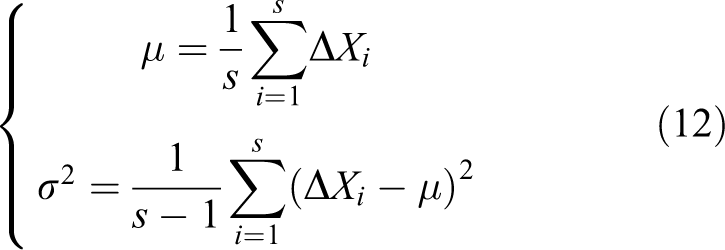
According to the Monte Carlo method, the mean and variance of the output position error of the mechanism can be obtained as
The reliability index is obtained as
Because G(X) follows a normal distribution, the kinematic reliability of the mechanism can also be expressed as

where Φ(•) is the standard normal distribution function.
Differentiating equation (14) with respect to the mean matrix,


where
Numerical example
The parameters of the mechanism are specified as follows: ai
= c = 1000 mm, e
1ij
/2 = 50 mm, and
Numerical example of error analysis of the mechanism
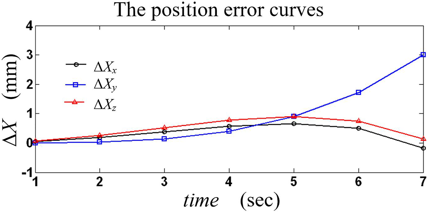
The length errors of the driving arms are given as Δa
1 = 0.5 mm, Δa
2 = −1 mm, and Δa
3 = −0.5 mm, and other errors are ignored. The output position error, Δ

Effect of driving-arm-length error on output errors of the mechanism as a function of time.
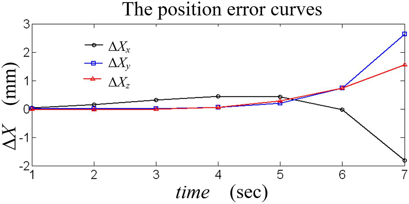
The length errors of follower links are given as Δc
21 = 0.5 mm, Δc
22 = 0 mm, Δc
21 = 0 mm, Δc
22 = −0.5 mm, Δc
31 = 1 mm, and Δc
32 = −1 mm, and other errors are ignored. Δ

Effect of the follower link’s length error on output errors of the mechanism as a function of time.
The configuration-position-error vector of the joint at points Bi
and Di
are given by Δ

Effect of each chain’s position on the mechanism’s position errors.
The pose errors of the coordinate systems are given by Bi
-xiyizi
, Ci
-xiyizi
, and Di
-xiyizi
:
Effect of the components’ attitude error on the mechanism’s position errors.
The length errors of the shafts CiCij
( j = 1, 2) are given as Δe
111 = 0.5, Δe
121 = −0.5, Δe
112 = 0.5, Δe
122 = −0.5, Δe
113 = 0.5, and Δe
123 = −0.5, and other errors are ignored. Δ
Effect of the connecting-shaft-length error on the mechanism’s position errors.
The following conclusions are obtained from Figures 5 to 9.
The length errors of the driving arms have little influence on the position error of the mechanism. The effect of the follower links’ length errors on the position error is larger than that of the driving arms. They affect both the position and pose accuracy of the mechanism when the lengths of two follower links differ. The length errors of shafts CiCij have a great influence on the position error of the mechanism. This effect will gradually increase with the lateral movement of the end effector. These factors, including the configuration-position errors and the pose errors of the joints, seriously affect the mechanism’s position and pose errors.
Numerical example of kinematic reliability analysis of the mechanism
The kinematic reliability of the mechanism can be analyzed using the Monte Carlo method when nominal dimensions and geometric tolerances of the parts are given, such as setting the lengths of the driving arms and follower links as ai = 1000 ± 1 mm and ci = 1000 ± 1 mm; the vector components of the configuration-position errors of the joints at Bi and Di as r 1ix = r 2ix = ±1 mm and r 1iy = r 2iy =r 1iz = r 2iz = ±0.5 mm; the lengths of links CiCij (j = 1, 2) as e 1i = e 2i = 100 ± 0.5 mm; and the vector components of the pose errors of the joints at points Bi , Ci , and Di as θBix = θBiy = ±0.3°, θCix = θCiy = ±0.3°, and θDix = θDiy = ±0.3°. Three joints can rotate freely around the z-axis; therefore, the z components of pose errors are 0. The number of samples is n = 400.
When the mechanism has a 7-s motion and the maximum permissible limit of the position error of the mechanism is Δ = [5 −5 8]T, kinematic reliability is determined based on the Monte Carlo method, as shown in Table 1.
Reliability calculation.

According to the data in Table 1, we find that the kinematic reliability of the mechanism was better when its end effector was near the initial position. With the lateral movement of the end effector, the kinematic reliability of the mechanism gradually reduced. In particular, when a driving arm moves to a horizontal position, the kinematic reliability reaches its lowest value, which is only 72.50%; therefore, the position of the mechanism should not be listed as being in a reasonable working space.
The calculations of position reliability in Table 1 are consistent with the kinematic-error distribution in Figures 5 to 9. When the position error of the mechanism increases, the kinematic reliability of the mechanism decreases.
Numerical example of kinematic reliability sensitivity analysis of the mechanism
According to equation (10), the response surface function of the kinematic position error can be constructed as

where C 1 = JPP (3,[1]), JPP (3,[1]) represents the first column of the 3 × 24 matrix JPP , C 2 = JPP (3,[2]), C 3 = JPP (3,[3,4,5]), JPP (3,[3,4,5]) represents columns 3, 4, and 5 of the 3 × 24 matrix JPP , C 4 = JPP (3,[6,7,8]), C 5 = JPP (3,[9]), C 6 = JPP (3,[10]), C 7 = JPP (3,[11,12,13]), C 8 = JPP (3,[14,15,16]), C 9 = JPP (3,[17]), C 10 = JPP (3,[18]), C 11 = JPP (3,[19,20,21]), C 12 = JPP (3,[22,23,24]), C 13 = JPJ (3,[1]), JPJ represents a 3 × 15 matrix, C 14 = JPJ (3,[2]), C 15 = JPJ (3,[3,4,5]), C 16 = JPJ (3,[6]), C 17 = JPJ (3,[7]), C 18 = JPJ (3,[8,9,10]), C 19 = JPJ (3,[11]), C 20 = JPJ (3,[12]), and C 21 = JPJ (3,[13,14,15]).
If Δ is the maximum permissible limit of the position error of the mechanism, according to equation (11), the limit state function of the kinematic reliability can be obtained

When the end effector of the mechanism reaches point P (22.8851, −907.9187, 110.9301)T in the workspace, the mean and variance of the output kinematic-position error can be obtained as
Kinematic reliability sensitivity to the mean of each error component (×10−3).

Kinematic reliability sensitivity to the variance of each error component (×10−3).

When the kinematic reliability sensitivity is 0, the reliability of the mechanism does not change with random errors. The magnitudes of the sensitivity’s absolute value indicate the rate at which the reliability changes with random errors.
The results of kinematic reliability sensitivity analysis can be seen in Tables 2 and 3.
Reliability sensitivity data in Tables 2 and 3 are in good agreement with the position errors of the mechanism in Figures 5 to 9.
We can see from the kinematic reliability sensitivity analysis in Tables 2 and 3 that the mean of the pose-error vectors,
The variances of the pose-error vectors
The influence of the pose errors of the joints on the kinematic reliability of the mechanism is much larger than that of the dimension errors of the components.
Conclusion
Using MATLAB software to generate random input errors that obey the normal distribution, the kinematic reliability of the modified Delta parallel mechanism was analyzed according to the Monte Carlo method under the condition of multiple errors. At the same time, a significant amount of experimental data for statistical analysis was easily obtained using this method. The reliability sensitivity of the modified Delta parallel mechanism was analyzed using the method of structuring the response surface function. Thus, the degree of influence of each error source on the kinematic reliability of the mechanism was determined. The assembly position and pose errors exhibited greater effect than dimension errors on the kinematic reliability of the modified Delta parallel mechanism.
Footnotes
Declaration of conflicting interests
The author(s) declared no potential conflicts of interest with respect to the research, authorship, and/or publication of this article.
Funding
The author(s) disclosed receipt of the following financial support for the research, authorship, and/or publication of this article: This work was partially funded by the USTL excellent talents training foundation (China; grant no. 2015RC12).
Appendix 1
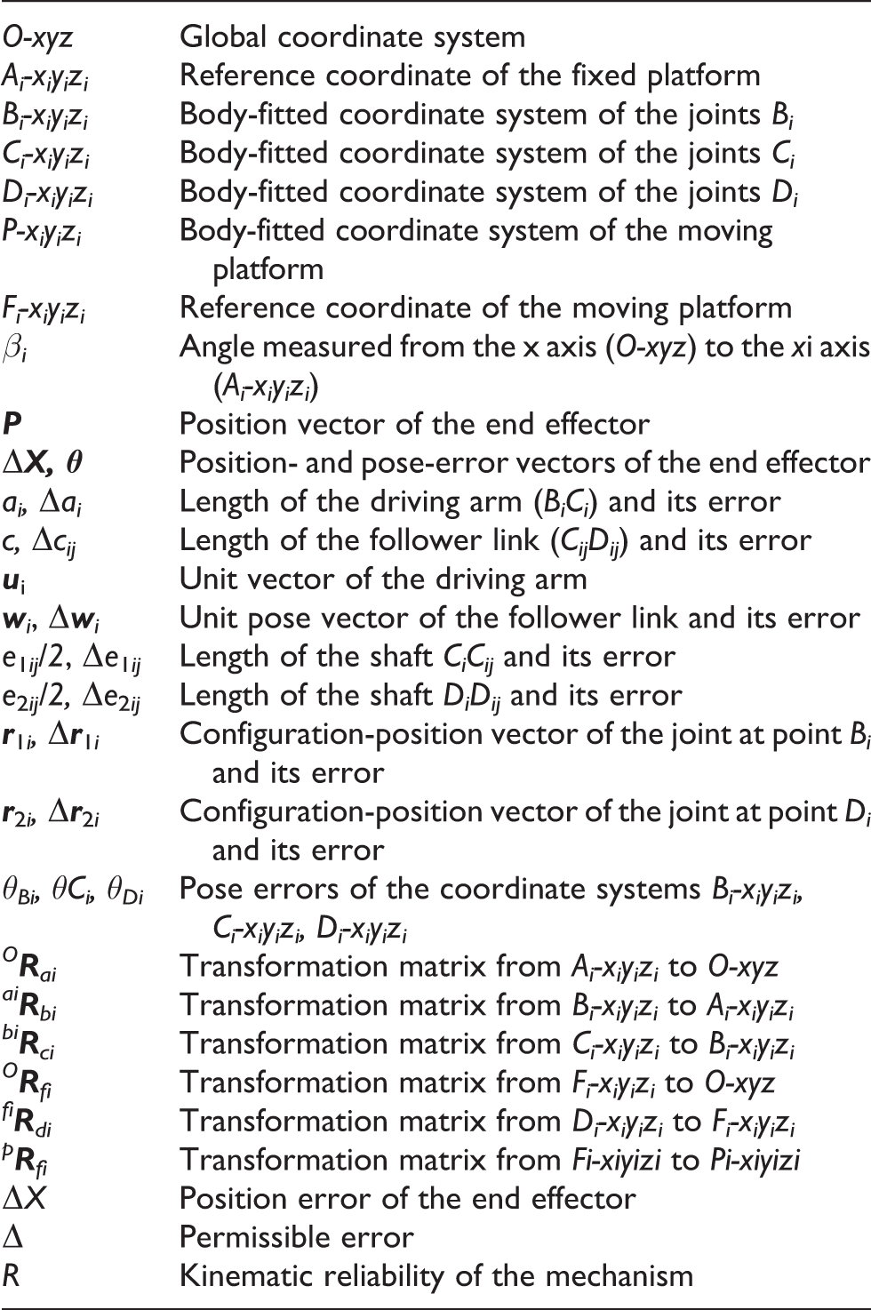
| O-xyz | Global coordinate system |
| Ai-xiyizi | Reference coordinate of the fixed platform |
| Bi-xiyizi | Body-fitted coordinate system of the joints Bi |
| Ci-xiyizi | Body-fitted coordinate system of the joints Ci |
| Di-xiyizi | Body-fitted coordinate system of the joints Di |
| P-xiyizi | Body-fitted coordinate system of the moving platform |
| Fi-xiyizi | Reference coordinate of the moving platform |
| βi | Angle measured from the x axis (O-xyz) to the xi axis (Ai-xiyizi ) |
|
|
Position vector of the end effector |
| Δ |
Position- and pose-error vectors of the end effector |
| ai, Δai | Length of the driving arm (BiCi ) and its error |
| c, Δcij | Length of the follower link (CijDij ) and its error |
|
|
Unit vector of the driving arm |
|
|
Unit pose vector of the follower link and its error |
| e 1ij /2, Δe 1ij | Length of the shaft CiCij and its error |
| e 2ij/2, Δe 2ij | Length of the shaft DiDij and its error |
|
|
Configuration-position vector of the joint at point Bi and its error |
|
|
Configuration-position vector of the joint at point Di and its error |
| θBi, θCi, θDi | Pose errors of the coordinate systems Bi-xiyizi, Ci-xiyizi, Di-xiyizi |
|
O
|
Transformation matrix from Ai-xiyizi to O-xyz |
|
ai
|
Transformation matrix from Bi-xiyizi to Ai-xiyizi |
|
bi
|
Transformation matrix from Ci-xiyizi to Bi-xiyizi |
|
O
|
Transformation matrix from Fi-xiyizi to O-xyz |
|
fi
|
Transformation matrix from Di-xiyizi to Fi-xiyizi |
|
p
|
Transformation matrix from Fi-xiyizi to Pi-xiyizi |
| ΔX | Position error of the end effector |
| Δ | Permissible error |
| R | Kinematic reliability of the mechanism |