
Abstract
Most of the reported three-dimensional chemical plume tracing methods use stereo sensing method to determine the next tracing step direction. For example, multiple sensors are used for detection in the left, right, up and down directions. Left and right detections are feasible for stereo sniffing; unfortunately, the same approach is infeasible for the up/down sensing of the quadrotor platforms because the propellers of the quadrotor continuously draw the air from the top and bring it down, which affects the sensing of the upper and lower sensors, and fails to determine the subsequent tracing step of up/down direction. Therefore, up/down sensing in the surging stage of chemical plume tracing is ineffective for quadrotor platforms (chemical plume tracing has two stages: surging and casting). To solve the problem, we propose an alternative that is not in the surging but in the casting stage of chemical plume tracing, by designing a new three-dimensional chemical plume tracing technique with variations of altitude (z-axis) control during the casting stage, which has never been considered in the previous works. Besides, we use a computational fluid dynamics software to study the airflow pattern of quadrotor platform. Subsequently, a fuzzy-based stereo-sniffing algorithm is developed by considering the quadrotor propeller’s air intake stream angle associated with the environmental wind direction angle, so as to improve the accuracy of stereo sensing. The results of the proposed solutions are verified and validated via both experimental and simulation approaches.
Introduction
The olfactory sense is one of the important senses in animals and is used for searching food, hunting and mating. Humans have been utilizing this important sense in training sniffer dogs, for example, in police and military operations. However, sniffer dogs have disadvantages, such as a long training time, a relatively limited serving time, restricted endurance and the inability to work under hazardous conditions. Therefore, researchers have been working hard to develop robots that can perform hazardous tasks such as chemical plume tracing (CPT) for detecting suspicious items in police operations. Over the last two decades, numerous studies have been conducted on CPT. However, these studies were mainly based on two-dimensional (2D) ground CPT methods that use wheeled mobile robots, such as the detection of methane gas leakages using a mobile robot. 1 The 2D CPT method has a serious limitation – the robot cannot detect a chemical plume above its height. From biological vectors that use three-dimensional (3D) flight tracing, such as moths, cover longer distances as compared with those that use 2D ground tracing, such as dogs. The chemical plume disperses into the atmosphere in 3D space, and a model of this dispersion would exhibit a chaotic, turbulent and non-linear nature. It can be modelled as a 3D Gaussian concentration dispersion model 2 as shown in Figure 1.
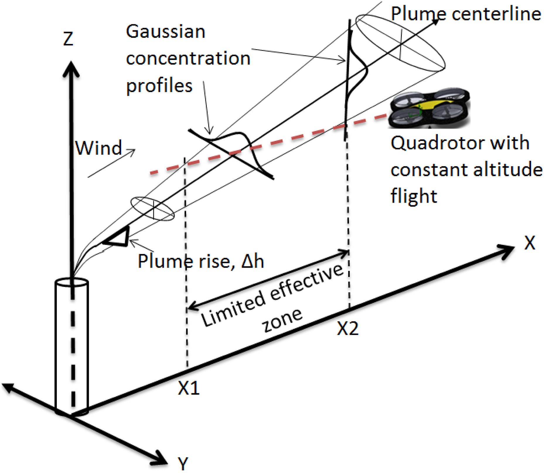
The constant altitude (z-axis) CPT method has only a limited effective sensing zone in the Gaussian concentration dispersion model. CPT: chemical plume tracing.
To illustrate the limitations of 2D CPT: Consider a flying object, such as a quadrotor performing CPT at a constant altitude (z-axis), and it has an effective detecting zone from X1 to X2 only; outside this zone, it would have poor detection as shown in Figure 1. The main reason for this is that the Gaussian concentration dispersion model has a plume rise Δh proportional to the x-axis (assuming that the chemical plume has a lighter density gas than air, e.g. methane gas); the chemical plume increases its altitude along the travelled distance. 2 Therefore, the variation of the altitude (z-axis) control in the casting stage of the 3D CPT must be investigated.
Attempts have been made to solve the 3D CPT problems. 3 –6 They contribute important exploratory studies in 3D CPT problems. In these works, multiple sensors are used for detection in the left, right, up and down directions.
Left and right detections are feasible for stereo sniffing; for this purpose, the differences between the left and right sensors are obtained, based on which the robot decides whether to turn left or right for the next tracing step.
Unfortunately, the same approach is not feasible for up/down sensing in real-world applications. Every flying mechanism generates airflow disturbances during flights, which can affect the chemical plume-sensing process. For instance, the propellers of quadrotor continuously suck in air from the top and bring it down, which causes no obvious contrasts between the upper and lower sensors, and insufficient to judge the subsequent tracing step of up/down sensing. For example, for the first scenario (refer to Figure 2(a)), chemical plume in the air is drawn from the top and bring it down and cause normalized sensing value for both upper and lower sensors; as for the second scenario as shown in Figure 2(b), neither upper nor lower sensors would detect the chemical plume because it has been blown away by the propellers before reaching the sensors.

The ineffective of up/down stereo sensing for quadrotor platforms, under two different scenarios: (a) normalized sensing value for both upper and lower sensors and (b) no detection for both upper and lower sensors.
Therefore, stereo sniffing for up/down sensing in surging stage of CPT is ineffective for quadrotor platforms. It is worth mentioning that CPT has two stages: casting and surging. 7 All previous CPTs so far have tracked against the wind direction (y-axis) and the variation for casting in the x-axis, with constant altitude (z-axis), that is, zigzag patterns at a constant altitude.
To overcome this problem, we design a new 3D CPT technique with variations of altitude (z-axis) control during the casting stage of CPT, which has never been considered in the previous works. Besides, we use a computational fluid dynamics (CFD) software to perform an airflow analysis of the disturbance generated by the quadrotors’ propellers. It is important to study how the airflow patterns of the quadrotor affect the chemical plume sniffing process and to incorporate it into the sensing algorithm. Hence, we develop a fuzzy-based stereo-sniffing algorithm that considering the quadrotor propeller’s air intake stream angle associated with the environmental wind direction angle. This improves the accuracy of stereo sensing because the most aligned propeller’s air intake stream angle with the environmental wind direction angle has highest weighting factor in detecting chemical plume – chemical plume always flows along with the environmental wind.
In this study, all the proposed solutions are discussed in third section, and the simulation and experimental results are discussed in fourth and fifth sections, respectively. Validation of the simulation and experiment results is discussed in fifth section. The final section presents the conclusions.
Related works
Some preliminary studies attempted to solve the 3D CPT problem. 8,9 Osório et al. 10 proposed the use of multiple gas sensors on a wheeled robot at different heights on a pole to generate a 3D gas distribution map. It is a good first attempt in 3D CPT. To the best of our knowledge, the first real 3D CPT with a flying mechanism was proposed by Ishida et al. 11 ; they used a blimp-based flying robot with multiple sensors placed at different locations on the blimp’s balloon (see Figure 3), which has the advantage of low airflow disturbance during flights, enabling reasonable left-right and up/down stereo sensing because the differences between sensors could be easily obtained in the low airflow disturbance flight condition. However, the flight controlling of the blimp-based flying robot is a very challenging problem. It has a serious drifting issue, even under a weak environmental wind condition. For example, drifting away from the commanded trajectory path, eventually, causes derailment during the CPT process. Moreover, CPT tasks require to trace against wind direction – but blimps drift along with the wind direction – this leads the implementing CPT task with blimp-based flying robot to be ineffective.

3D CPT with blimp-based flying robot. 11 3D: three-dimensional; CPT: chemical plume tracing.
In the latest study on 3D CPT, quadrotors have been suggested. 12,13 Neumann et al., 14,15 have made significant contributions to some significant aspects of 3D CPTs using quadrotors, such as the integration of the Infotaxis algorithms, gas distribution mapping and particle filter algorithms. However, they have not considered the altitude control in the casting stage of CPT, and the altitude was kept constant manually during the experiments. 16 Besides, the impacts of airflow disturbances generated by a quadrotors’ propellers have not been taken into account for designing their CPT algorithms. The airflow disturbances have a significant influence on the chemical plume-sensing ability of quadrotors; for example, propellers blow away chemical plumes before sensors can detect them. Therefore, in this study, we design a new 3D CPT technique that considers the impact of airflow disturbances generated by propellers.
As for the existing studies on 3D CPT algorithm in simulations, some of them implemented the simple representation model of flying robot (not the real model) to investigate the 3D CPT algorithms. For instances, Awadalla et al. 4 used a virtual robot in the Matlab platform and Gao et al. 3 used a simplified model of flying robot with four sensors setup for detection in the left, right, up and down directions, as shown in Figure 4. Recently, Soares et al. 17 has conducted a 3D CPT experiment in a wind tunnel. They mounted an emulated aerial robot on the traversing system of the wind tunnel; with this setup, they tested their 3D upwind-surge algorithm but without considering the airflow disturbances that generated from the flying mechanism. Nevertheless, they have laid an important foundation for 3D CPT research, by experimenting 3D CPT in a giant wind tunnel.

An example of the mounting positions of four sensors setup: upper, lower, left and right sensors.
In these studies, they had neglected that the flying mechanism of the realistic flying robot model can generate airflow disturbances during flight and cause the impractical of up/down stereo sensing (e.g. the propellers of the quadrotor, continuously draw the air from the top and bring it down, which affects the sensing of the upper and lower sensors). Therefore, further improvement of 3D CPT simulation that is closer to the real world needs to be developed by considering aspects such as real-scale 3D models of robots and taking consideration of airflow disturbance of flying mechanism. In the present study, we developed a 3D CPT simulation with a real-scale model of quadrotor and simulating the airflow disturbance of quadrotor; this helps us to realize the practical problem of up/down stereo sensing in the quadrotor platform, which the previous researchers have overlooked, and we will tackle the problem with our proposed solution.
Proposed solutions
This section discusses the proposed solutions for 3D CPT problems such as overcoming airflow disturbances generated by the flight mechanism, which affects the chemical sniffing process; solving the limitations of gas sensors; developing a stereo-sensing algorithm; and investigating effective 3D chemical plume-casting methods with altitude control. To address the above-mentioned issues, the following procedures are considered: (a) selection criteria of a suitable flight mechanism; (b) studying the selected flying mechanism using CFD airflow analysis; (c) designing a sophisticated algorithm to overcome long recovery problems of gas sensors; (d) incorporating the stereo-sniffing algorithm into the quadrotors’ system; and (e) designing a technique of varying altitude (z-axis) in the casting stage of the tracing. By combining all these proposed procedures, we present a complete CPT solution using the quadrotor as the platform.
Selection criteria of flying mechanisms
First, an appropriate flying mechanism needs to be considered before designing the 3D CPT technique. Two critical criteria need to be met for the selection of a flying mechanism. First, a high degree of locomotion manoeuvrability is required to perform CPT movements agilely. Second, the airflow disturbances generated during flight need to be low to avoid interference during the chemical plume-sensing process. However, a trade-off exists between these criteria; a high degree of locomotion manoeuvrability generates high airflow disturbances and vice versa. Given the contradictory conditions, to realize effective 3D CPT, the flying mechanisms need to be studied.
Two main categories of flying mechanisms are available, namely, aerostats and aerodynes. 18 The aerostat flight gains its lift through the use of a buoyant gas (such as helium) balloon and a blimp-based robot, making it lighter than air. Lightweight propellers that do not need to rotate at a high speed are used to control the aircraft’s direction. Hence, this mechanism generates the lowest airflow disturbance during flight compared with other flying mechanisms. However, it has the lowest degree of mobile manoeuvrability. This implies that an aerostat is good for chemical plume sensing owing to its low airflow disturbance; however, the flight controllability of aerostat is a challenging problem. It is difficult to hold on a fixed position, even though it is under a weak environment condition. 19 It also has a serious drifting issue, which drifts away from the commanded trajectory path, eventually, causes derailment during the CPT process.
In contrast, aerodynes, such as fixed-wing aircraft, rotorcrafts, multirotor aircraft and flapping-wing aircraft, are heavier than air but they have a higher degree of manoeuvrability as compared to aerostats.
Among aerodynes, quadrotors meet the requirement of the agile movement of moth-inspired CPT techniques because it has the highest degree of mobile manoeuvrability. Besides, it has a well-developed flight control system available in the market and high potential in the future. However, it also has the highest airflow disturbance, which affects the chemical plume-sensing process. We therefore chose quadrotor to perform CPT tasks, conducting a study of airflow analysis to address the issue of high airflow disturbance.
Airflow analysis of quadrotor systems
To understand the airflow disturbance generated by the propellers of a quadrotor, the flow simulation function of a 3D modelling CFD software, SolidWorks, is developed to obtain the simulation results of the airflow analysis. We draw an exact scale dimension 3D model of a quadrotor, as shown in Figure 5(a). Then, we simulate the spinning of propellers during the flight to generate the airflow analysis. Figure 5(b) to (f) shows the analysis results.
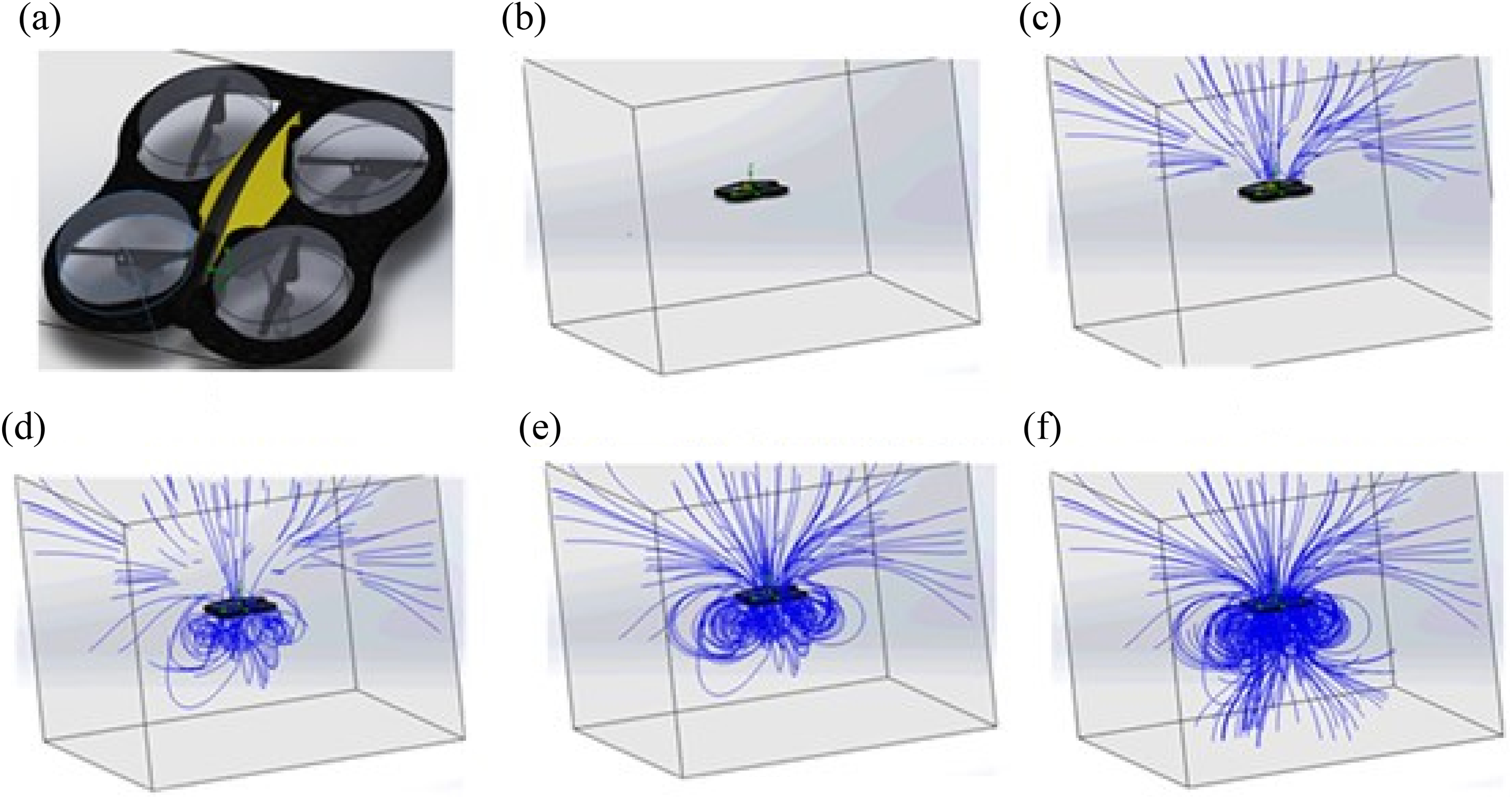
Airflow analysis simulation of a quadrotor system: (a) the 3D model of quadrotor; (b) simulating the quadrotor in the middle of a cube space; (c) drawing the surrounding air above the propellers to the quadrotor; (d) and (e) circulating some of the air back to the propellers, to form airflow eddies; and (f) emitting out the air. 12
From the simulation results, it can be observed that there are three regions in the airflow analysis: air intake, airflow eddies and air exhaust (see Figure 6). The airflow pattern is represented by dashed lines, and the airflow direction is represented by arrows. The air intake region has four main air streams intake into four different propellers; it indicates the sniffing areas of the quadrotor. Likewise, it can be reasoned that four chemical sensors can be mounted on each propeller to detect chemical plumes that come from four different air streams and directions. In the second region, at the airflow eddies, the air taken in circulates back to the propellers, it is only formed during the altitude of quadrotor is changing. 20 If the four chemical sensors are mounted below each propeller, they can detect the chemical plume more than twice and increase the sensing opportunities. In conclusion, the airflow analysis results show that the airflow disturbance generated by the propellers of quadrotor has no significant impact on the sniffing process, provided the chemical sensors are correctly mounted below each propeller. 12
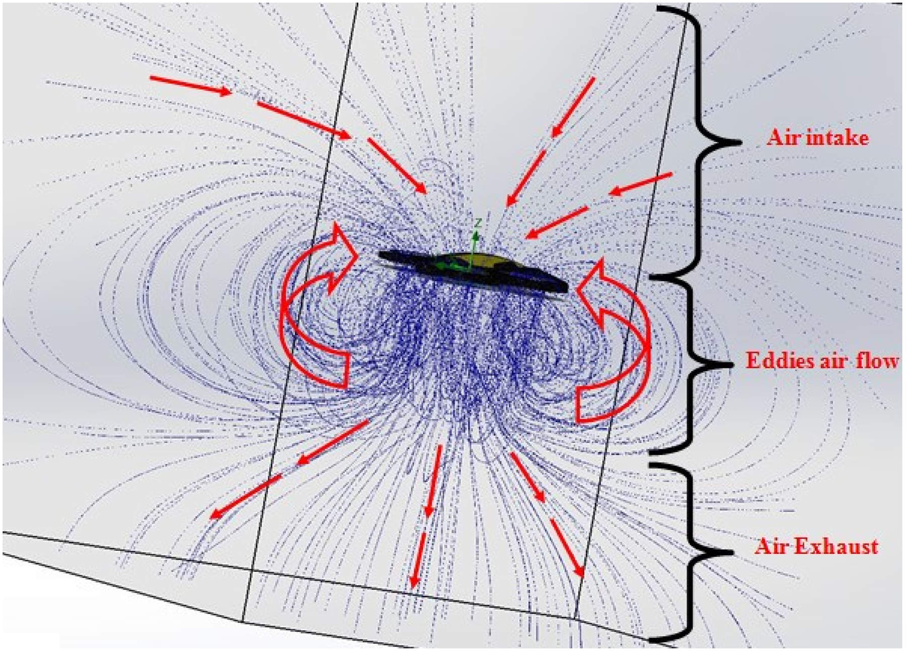
Three regions of the quadrotors’ airflow pattern: air intake, airflow eddies and air exhaust. 12
Chemical plume-sensing compensation algorithm
In this study, semiconductor Metal Oxide Semiconductor (MOX) gas sensors are used to detect the target chemical plumes. The MOX gas sensors have a fast response in gas detection, but they have a limitation of long recovery time after the removal of the target chemical plumes. 21 Hence, a compensation algorithm is needed to use this type of gas sensor in sniffer robots. From the characteristic of MOX gas sensors shown in Figure 7, we can see that the gas sensor has a fast response to detect the target chemical plume (in the blue region), with less than 2 s delay time. However, it takes approximately 70 s to return to its baseline after the removal of the target chemical plume (beyond the blue region). 22 It causes a delay in responses when sniffer robots are off-track of the chemical plume, which eventually leads to tracing failure.

The long recovery time characteristic of MOX gas sensors. 22
In this study, a sensing algorithm based on evidential theory, which uses certainty factors and evidential reasoning, is proposed. 23 The evidential reasoning is based on transient responses because the trend of transient responses can be reliable evidence to judge the sensing situations. 24 According to the chemical plume dispersion model, the odorant concentration is not linearly distributed from high to low concentrations and will not indicate the chemical plume flow direction. On this basis, when performing CPT tasks, sensing information, such as within a chemical plume (in-track) or out of a chemical plume (out-track), is more important than odorant concentration information because it does not indicate the chemical plume flow direction. In fact, the chemical plume flow direction can be indicated by the wind flow direction. Subsequently, MOX gas sensors just need to judge in-track or out-track sensing scenarios during CPT, instead of judging odorant concentrations. To judge in-track or out-track sensing scenarios, the transient response trend of MOX gas sensor is a reliable indication or evidence. For the in-track sensing scenario, if an MOX gas sensor without a target chemical plume changes to include exposure to a chemical plume, it would have continuous positive transient signals. If a few positive transient signals are continuous in subsequent discrete times, it could indicate the in-track sensing scenario. Likewise, if there is only a positive transient signal in a discrete time, it might be a false and distorted transient signal from the sensor’s error, and this would be insufficient evidence to judge the sensing scenario. For the out-track sensing scenario, a negative transient signal has a smaller gradient value than the positive transient signal because of slow recovery problems. However, if there are a continuous number of negative transient signals in subsequent discrete times, it could indicate the out-tracing sensing scenario. Similarly, if there is only a negative transient signal per discrete time, then it is an insufficient evidence to judge the scenario. Based on this premise, the judgement of the out-tracing sensing scenario can be significantly improved during the delay time, if there is an evidential reasoning for a number of continuous negative transient signals in subsequent discrete times, instead of the sensor value resuming the baseline threshold.
Certainty factor theory and evidential reasoning are used to measure the above-mentioned transient sensing evidence in the numerical value. It is based on the measurement of the hypothesis, and the measurement is determined by the certainty factor (cf). The maximum value of cf is +1.0 if the hypothesis is definitely true, while it would be −1.0 if the hypothesis is definitely false. Likewise, there is some evidence that if a hypothesis is almost certainly true, a cf value of +0.8 would be assigned to this evidence. These cf values are tuned by trial and error. To judge in-track or out-track sensing scenarios for CPT tasks, an MOX gas-sensing evidential reasoning system with certainty factors is developed; it consists of a set of rules that have the following syntax: /*MOX = Gas-sensing expert system with certainty factors *PGTT = Positive gas transient threshold *NGTT = Negative gas transient threshold
Rule: 1
IF: Gas-sensing value t > Gas-sensing value t − 1 AND: Transient signal Tn > PGTT THEN: In-track sensing scenario {cf 0.8}
Rule: 2
IF: Gas-sensing value t > Gas-sensing value t − 1 AND: Transient signal Tn < PGTT AND: Gas-sensing value < Gas-sensing threshold THEN: In-track sensing scenario {cf 0.2}
Rule: 3
IF: Gas-sensing value t > Gas-sensing value t − 1 AND: Transient signal Tn < PGTT AND: Gas-sensing value > Gas-sensing threshold THEN: In-track sensing scenario {cf 0.45}
Rule: 4
IF: Gas-sensing value t < Gas-sensing value t − 1 AND: Transient signal Tn > NGTT THEN: Gas plume is not detected {cf 0.70}
Rule: 5
IF: Gas-sensing value t < Gas-sensing value t − 1 AND: Transient signal Tn < NGTT AND: Gas-sensing value < Gas-sensing threshold THEN: Gas plume is not detected {cf 0.75}
Rule: 6
IF: Gas-sensing value t < Gas-sensing value t − 1 AND: Transient signal Tn < NGTT AND: Gas-sensing value > Gas-sensing threshold THEN: Gas plume is not detected {cf 0.15}
Evidence of fired Rule 6 at the current time t
Rule: 7
IF: Current Fired Rule is Rule 6 AND: Previous Fired Rule at t − 1 is Rule 6 AND: Previous Fired Rule at t − 2 is Rule 6 ⋮ AND: Previous Fired Rule at t − n is Rule 6 THEN: Series of evidence of Fired Rule 6
Rule: 8
IF: Series of evidence of Fired Rule 6 THEN: Gas plume is not detected {cf 0.68}
For the set of rules, gas-sensing value signal patterns are observed as evidence. First, the gas sensor value at the current time t is compared with the gas-sensing value at the previous time t − 1; this will be evidence of positive or negative transient signals. Second, the transient signal is compared with the positive gas transient threshold (PGTT) or the negative gas transient threshold (NGTT) as evidence of dynamics response. Third, the gas-sensing threshold (or baseline value) will be considered as evidence of the previous sensing status. Lastly, the rules 6, 7 and 8 will be used to find a reason for the long recovery time problem of MOX gas sensors. Based on the set of rules designed, only rules 6 and 8 have chances to occur concurrently, and their cf value can be combined using equation (1)

To prove the validity of the certainty factor sensing, we conducted experiments and compared with another two commonly used algorithms such as simple threshold method and transient response algorithm. The experiments involved two different sensing scenarios: from non-detecting to detecting – to test the rise time response; and from detecting to non-detecting – to test the recovery time response.
Figure 8 shows the results of the rise times, recovery times and accuracy of the algorithms. For the rise time performance, certainty factor sensing algorithm has an average rise time of 1.876 s, which is 0.822 s slower as compared to transient response algorithm’s average rise time of 1.054 s. This is acceptable because it will not affect much in chemical plume tracking task of sniffer robots, as compared to the long recovery time of the simple threshold method (averagely 48.522 s).

The comparison of rise times, recovery times and accuracy for simple threshold, transient response and certainty factor sensing.
The average recovery times of transient response and certainty factor sensing algorithm are 1.126 and 2.258 s, respectively. The reason behind slightly slower rise and recovery times of certainty factor algorithm as compared to transient response algorithm, is to increase the accuracy and reliability, so as to overcome the problem of high sensitivity and also over response to the noisy and distorted transient signals of MOX sensors, which is the main limitation of transient response algorithm. This can be observed from Figure 8 that the accuracy of the transient response algorithm is 87.9%, whereas the accuracy of the certainty factor sensing is 100%.
To emphasize again, the critical failure factor of chemical plume tracking task of sniffer robots with MOX gas sensor is the long recovery time (which is averagely 48.522 s from the simple threshold method). Therefore, the result of certainty factor sensing algorithm in recovery time is significant.
Incorporating stereo-sniffing algorithm into the quadrotors’ system
The airflow analysis study of the quadrotor system has been investigated in ‘Airflow analysis of quadrotor systems’ section. We identified a pattern of four main streams of active air intake as an important factor that influences the sniffing process. Likewise, the certainty sensing algorithm for judging whether the robot is in-track or out-track has been developed in ‘Chemical plume-sensing compensation algorithm’ section. This section incorporates the findings of the previous two sections with the fuzzy expert system functioning as the stereo-sniffing algorithm. The purpose of the stereo-sniffing algorithm is to judge the CPT direction of the subsequent tracing step.
Before designing the fuzzy inference structure, the formula for calculating the environment’s wind direction weighting factor is needed. On this basis, the chemical plume disperses along the wind direction although in a chaotic way. The relation between the azimuthal angle of the environmental wind direction and the azimuthal angle of the mainstream of air intake by the quadrotor propeller is an important weighting factor that must be considered for calculating the subsequent steps of the CPT direction. Closer the two angles are, the higher the weighting should be. The equation of this weighting factor can be expressed as below

where Wf pn is the weighting factor for propeller n{1,2,3,4}, α wa the Azimuth angle of the environment wind direction and β pna the Azimuth angle of the air intake stream direction of propeller n{1,2,3,4}.
Figure 9 shows that the air intake stream angle of propeller 1 with β p1a has the highest weighting factor in this scenario because β p1a is closely aligned with α wa, as compared with other propellers. This can be calculated using equation (2).
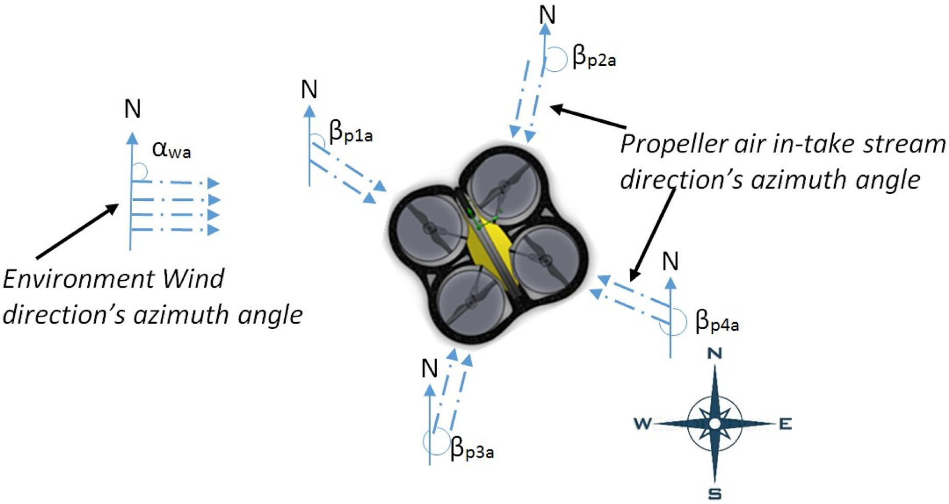
The wind direction angle associated with quadrotor propeller’s air intake stream angle.
The weighting factor of the wind direction angle associated with the quadrotor propeller’s air intake stream angle can be integrated with the certainty sensing algorithm to develop a fuzzy inference system for stereo sniffing, as shown in Figure 10. It is used to compute the CPT direction of the subsequent tracing step. The fuzzy inference system of stereo sniffing has four rules for each air intake stream or each propeller. These rules are the product

Figure 10 shows an example for calculation of the fuzzy inference system at various certainty sensing factors and wind weighting factors. After evaluating the four fuzzy rules, it is aggregated into a single fuzzy set for the overall fuzzy output. The last step in the fuzzy inference process is defuzzification. The defuzzification method is called the centroid technique, which is used to calculate the centre of gravity (COG) of the overall fuzzy output set. It can be expressed as


Fuzzy inference structure of stereo sniffing with an example of certainty sensing factors of cf p1 = 0.8, cf p2 = 0.2, cf p3 = 0.45 and cf p4 = 0 and wind weighting factors of wf p1 = 0.833, wf p2 = 0.333, wf p3 = 0.666 and wf p4 = 0.166.
The calculated output of equation (4) indicates the direction angle of the next tracing step.
To verify the performance of the fuzzy-based stereo-sniffing algorithm, we conducted the experiments with two different cases that a plume source changes the orientation from time ti = 0 to ti = 1, as shown in Figure 11. For case 1, the plume source was located at 45° at time t = 0 s, then it was shifted to 90° after time t = 10 s. Likewise, for case 2, the plume source was first located at 90° (t = 0 s), then changed to 135° (t = 10 s). We compared the fuzzy-based sensing’s COG with the COG directly calculated from the bar chart of the sensors’ raw values (parts per million). The COG from the bar chart of the sensors’ raw values has a maximum error of 84.44%, but the COG from the fuzzy-based sensing has a small maximum error of 7.688% only. These results show that the COG of the fuzzy-based sensing has the higher accuracy to estimate the direction angle of the next tracing step.
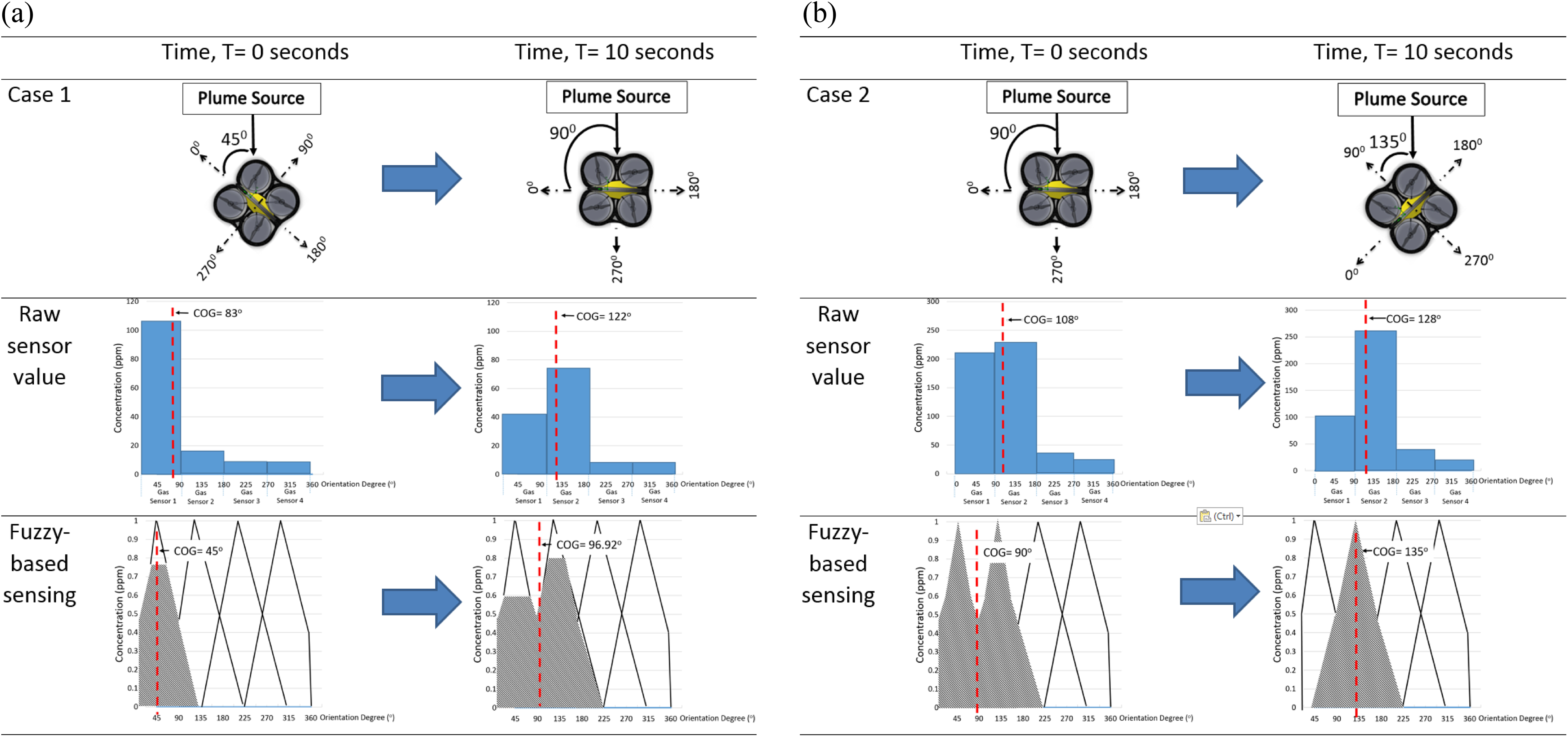
The performance of the fuzzy-based stereo-sniffing algorithm: (a) Case 1, changing the orientation of quadrotor from 45° to 90° and (b) case 2, changing the orientation of quadrotor from 90° to 135°.
Variation of altitude (z-axis) control in the casting stage of the 3D CPT algorithm
Chemical plume dispersion has a chaotic nature, which is always stretched and twisted by the environment’s airflow; therefore, CPT involves two stages: surge and cast tracing. In surge tracing, stereo sniffing is applied whenever the chemical plume is detected; in other words, it is an in-track sensing scenario. On the other hand, cast tracing is applied whenever the tracing of the chemical plume is lost or when there is out-track sensing. To the best of our knowledge, cast tracing methods that have been commonly applied in previous works are zigzag and spiral casting, as shown in Figure 12 (a) and (b). Both these casting methods have their own advantages. Zigzag casting has better efficiency at the beginning of the lost track sensing scenario because it is a faster way to return to the chemical plume tracks. However, spiral casting can be used in a condition when chemical plume tracks had been lost for a long period because it is a faster way to discover the new track again. Both these casting methods are applied mostly in 2D ground tracing that uses wheeled mobile robots. Zigzag casting is designed to track along the up-wind direction (y-axis); it tracks the orthogonal zigzag movement where variation in the x-axis slowly increases its zigzag wavelength after each iteration. Spiral casting is designed with variations in the x- and y-axes in the spiral movement, and then it slowly increases its spiral radius after each iteration. These two casting methods have one thing in common – they do not consider variation in altitude (z-axis) because they are 2D tracing. 25,26

(a) 2D zigzag-casting method (top view) and (b) 2D spiral-casting method (top view). 2D: two-dimensional.
As previously stated, the basis of the Gaussian dispersion model is that the plume rise Δh is proportional to the x-axis (assuming that the chemical plume has methane, which is lighter than air); therefore, the chemical plume increases its height along the travelled distance. Hence, constant altitude (z-axis) casting is not effective at all (See Figure 1).
In this study, we develop zigzag casting with variation in the altitude (z-axis); it is defined by the equations (5) to (7). For each iteration of the cycle time t cycle i , the t cycle i will increase by the factor σ (extending factor of cycle time) and lambda λxi (x-axis direction parameter) will also change the sign for each iteration of the zigzag movement. Within one iteration, the altitude’s phase angle θt increases from 0 to 2π, which is amplified with the phase angle factor ωz; this provides the variation in the z-axis for an iterative zigzag movement. The wavelength of the z-axis is determined by the altitude’s amplitude r and is slowly increased for each iteration. Lastly, the pattern-determining factor q create the alternate altitude pattern for each iteration. This is illustrated in Figure 13.


where


3D zigzag-casting method (isometric-, top-, and front-view). 3D: three-dimensional.
The proposed spiral casting with variation in the z-axis is also developed; it is defined by equations (8) to (10). For each iteration of the cycle time t
cycle i
, the t
cycle i
will increase by the factor σ (extending factor of cycle time), the spiral’s radius ri
will increase by the factor μ (expanding factor of spiral’s radius). The value of pattern-determining factor qi
will increase by one for each iteration of the spiral movement, to produce the alternate altitude pattern for each iteration. Within one iteration, the altitude’s phase angle θt increased from 0 to 2π; this provides variation in a circular effect of x- and y-axis, and a variation in the altitude (z-axis) for an iterative spiral movement but only the z-axis is amplified with the phase angle factor ωz. The circular effect of x-, y- and z-axes are based on the centre point (


where

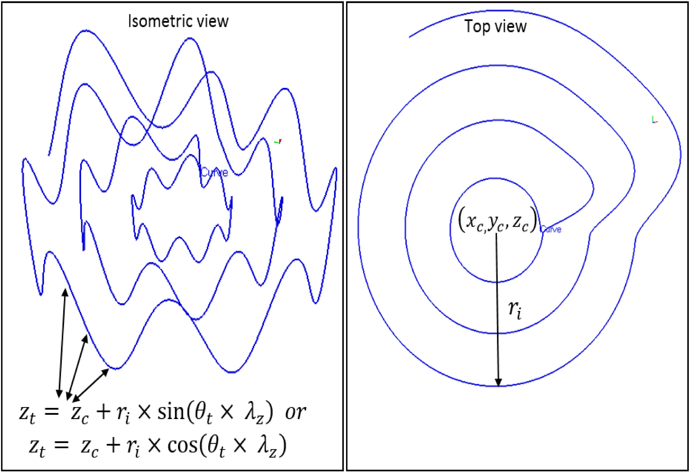
3D spiral-casting method (isometric- and top-view). 3D: three-dimensional.
Integration of proposed solutions
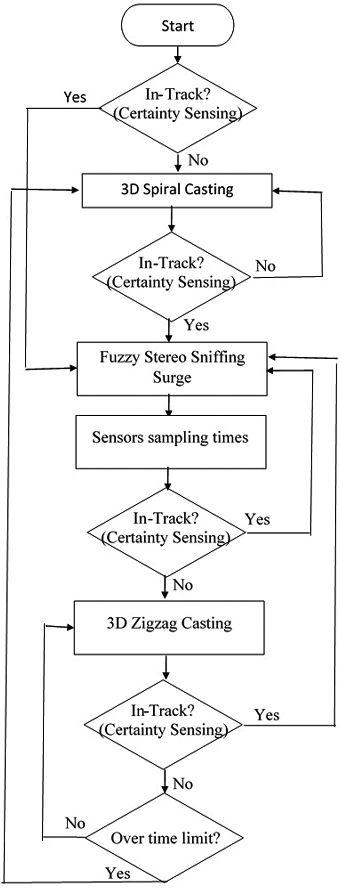
The entire solution can be integrated as shown in Figure 15. First, certainty sensing is used to detect whether it is an in-track or out-track sensing scenario. If the CPT is on the track, it should fire the fuzzy stereo-sniffing surge. If the CPT is out of the track, 3D spiral casting will be triggered for the first time. The reason for triggering 3D spiral casting first instead of 3D zigzag casting is that 3D spiral casting can detect the trace of the chemical plume faster when the previous chemical plume information is unknown or when there is insufficient information about it. The 3D spiral-casting technique is applied until the in-track sensing scenario is detected, and then the fuzzy stereo-sniffing surge will be fired. Based on this premise, the out-track sensing scenario could occur again because the chemical plume is non-linear. Once this occurs, there is a sensing sampling time to make sure it is in the out-track sensing scenario, then zigzag casting will be used to find the chemical plume track. In this situation, zigzag casting is more effective than spiral casting because the previous detection of the chemical plume is known, and it is not too far away; therefore, zigzag casting could rediscover the in-tracing sensing scenario quickly. If it is back to in-tracing, fuzzy stereo sniffing will be employed again. However, if zigzag casting has failed to discover the chemical plume track in a certain period, it will trigger spiral casting again to increase the chances of finding some trace of the chemical plume.
The overall block diagrams of the proposed solutions.
Simulation results
We developed a physics engine 3D CPT-tracing simulation, 27 as shown in Figure 16. A real-scale dimension quadrotor was simulated in an open 3D space. Four gas sensors were mounted below each propeller, as described in ‘Airflow analysis of quadrotor systems’ section. Each sensor’s response was captured in a graph, as shown in Figure 16. A 3D dispersion of a chemical dispersion source was simulated by using the filament model proposed by Farrell et al. 28 We applied three independent Gaussian random factors to the filaments’ coordinates (x-, y- and z-axis), to generate 3D intermittent plume with the time-variant characteristic. The odorant concentration was represented by the intensity of colours from dark red to light blue.
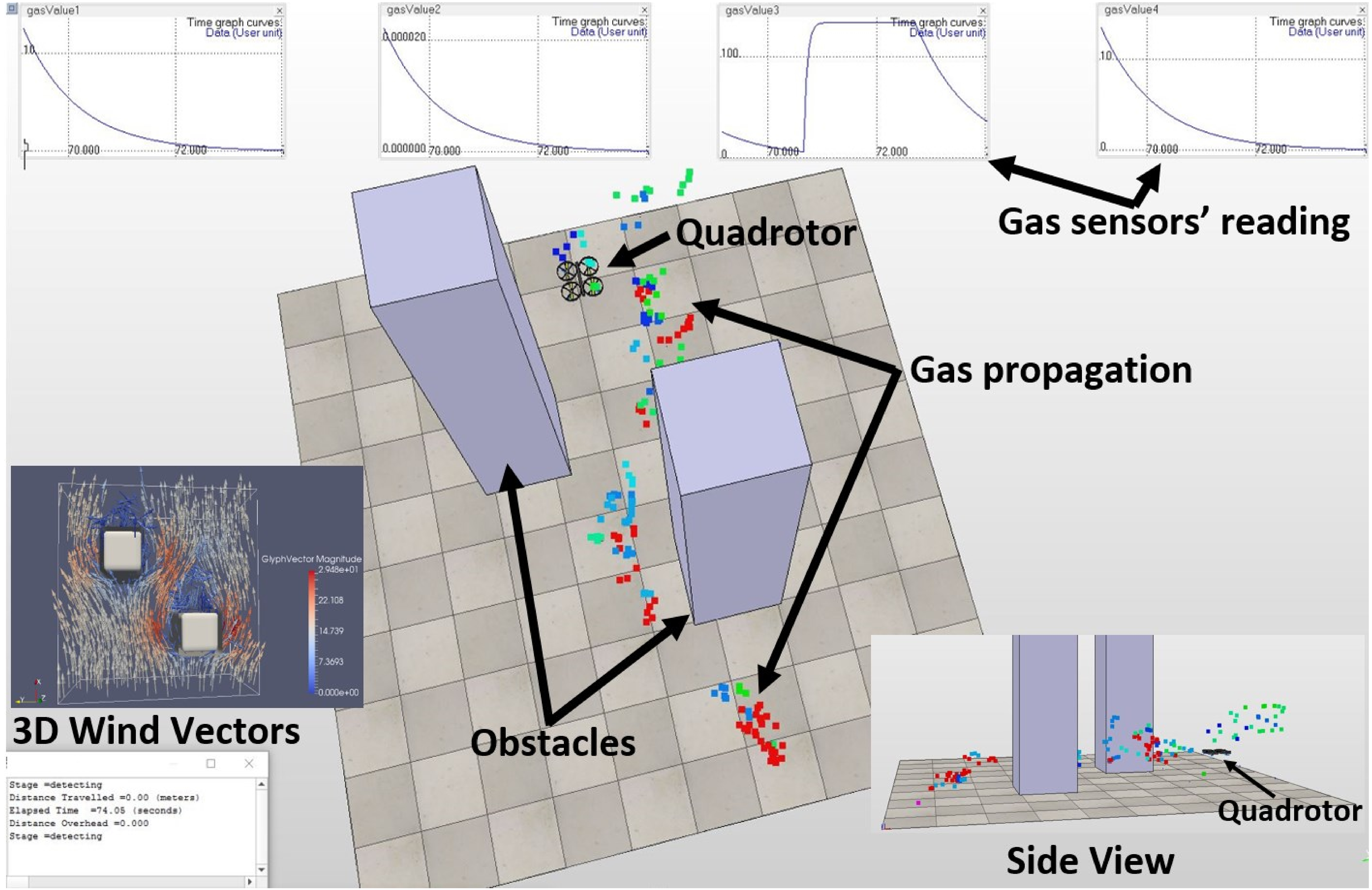
The illustration of 3D physics engine CPT simulation, showing a quadrotor is tracing toward a gas source. 3D: three-dimensional; CPT: chemical plume tracing.
For a truthful gas, dispersion simulator has to first generate the environment wind vectors by a CFD software, and then followed by simulating plume propagation model. Therefore, we used an open source CFD software, TYCHO, which uses a Lagrangian remap version of piecewise parabolic method 29 to generate the environment wind vectors. Figure 17 shows that the TYCHO generated wind vectors in a 3D space with a rectangular cuboid obstacle at the middle. The colours of the arrows indicate the wind speed according to the intensive colours from blue (minimum speed) to red (maximum speed). The arrows’ direction indicates the wind vector. These wind vectors are then be integrated into our CPT simulator, where substituting into the wind elements of the filament-based equation. Figure 18 shows the outcome of a truthful 3D gas dispersion incorporated with CFD wind vectors, where the plume propagates along the wind vectors and surrounds over the contour of the obstacle, as shown in Figure 18. There are two sources for noise of plume dispersion: the Gaussian random factors of the filament model and the turbulence wind vectors from the CFD. The plume source released from a range of 20–80 filaments per second with time-variant. The average wind flow set in the CFD is 5 m/s and the speed of the quadrotor ranged from 0.05 to 0.25 m/s, according to the number of the casting iterations.

3D wind vectors generated by TYCHO, simulating the wind vectors with an obstacle block in the middle of a cube space. 27 3D: three-dimensional.

The result of the incorporating CFD into plume propagation model, the plume propagates along the wind vectors and surrounds over the contour of the obstacle. CFD: computational fluid dynamics.
Several experiments have been conducted to investigate the effectiveness and efficiency of 3D CPT. There are two key performance indicators to evaluate the CPT performance: distance overhead and elapsed time. Distance overhead is defined as the total travelled distance divided by the distance of the shortest path to the source. A smaller distance overhead value indicates better performance. Similarly, a shorter elapsed time indicates better performance.
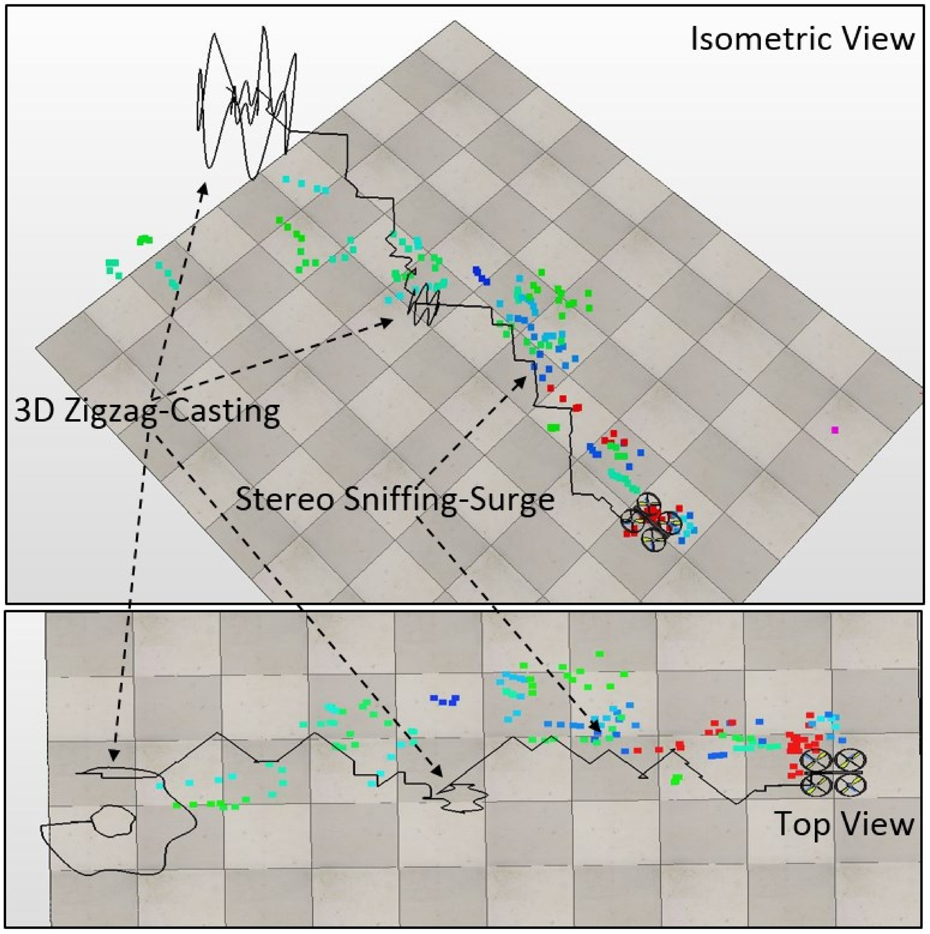
First, the parameters that influence the performance of 3D zigzag casting in terms of the variation of the altitude (z-axis) are investigated. Equation (5) implies that there are two parameters, the spiral’s radius r and phase angle factor ωz, which influence the variation in the z-axis. Figure 19 shows one of the scenarios of 3D zigzag casting CPT simulation.

The illustration of 3D zigzag-casting simulation (isometric- and top-view). 3D: three-dimensional.
From Table 1, the impact of the spiral’s radius r is investigated; it varies from 0.01 to 0.08 m, and phase angle factor ωz has a constant value of 4. Table 1 shows that over-assigning a high value to the spiral’s radius r can increase both the elapsed time and the distance overhead. Eventually, this will lead to a failure in the CPT task. This is because if the spiral’s radius r is over-assigned, it will have a higher amplitude on the altitude (z-axis) or fluctuation. The over-fluctuation flights will increase the elapsed time and the travelling distance, eventually leading to a failure in the CPT task. However, an under-assigned spiral’s radius r would have a small amplitude on the z-axis, and it would require more iterations of zigzag casting, which could reduce the overall performance. From Table 1, it is clear that experiment 3 with spiral’s radius r of 0.04 m gives an optimistic result with the shortest elapsed time and second smallest distance overhead.
Simulation results of 3D zigzag casting with constant phase angle factor ωz.
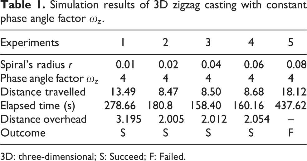
3D: three-dimensional; S: Succeed; F: Failed.
From Table 2 the impact of ωz has been investigated from 2 to 6, with a constant value of spiral’s radius r of 0.04 m. It can be observed that under- or over-assigned values of ωz produces poor performance. Therefore, from Table 2, it can be seen that experiment 3 has the most optimistic result in terms of both distance overhead and elapsed time.
Simulation results of 3D zigzag casting with constant spiral’s radius r.

3D: three-dimensional; S: Succeed; F: Failed.
Second, the parameters that influence the performance of 3D spiral casting in terms of the variation of the z-axis are investigated. In equation (8), there are two parameters, spiral’s radius ri and phase angle factor ωz, which influence variations in the altitude (z-axis). Figure 20 shows one of the scenarios of 3D spiral-casting CPT simulation.
The illustration of 3D Spiral-casting CPT simulation (isometric- and top-view). 3D: three-dimensional; CPT: chemical plume tracing.
From Table 3 we investigate the parameter ri from 0.05 to 0.4 m at a constant value of ωz = 6. From the results, it can be observed that the under- or over-assigned value of spiral’s radius ri would lead to poor performance. The under-assigned spiral’s radius ri has a small amplitude on the altitude (z-axis); it would require more iterations of spiral and increase both the elapsed time and the distance overhead. Eventually, it will lead to a failure in the CPT task. The over-assigned spiral’s radius ri would also have a higher value of distance overhead and elapsed time because it has a larger amplitude on the altitude (z-axis), and it would increase the elapsing time and travelling distance. The optimistic result having the shortest elapsed time and distance overhead is spiral’s radius ri of 0.2 m.
Simulation results of 3D spiral casting with constant phase angle factor ωz.
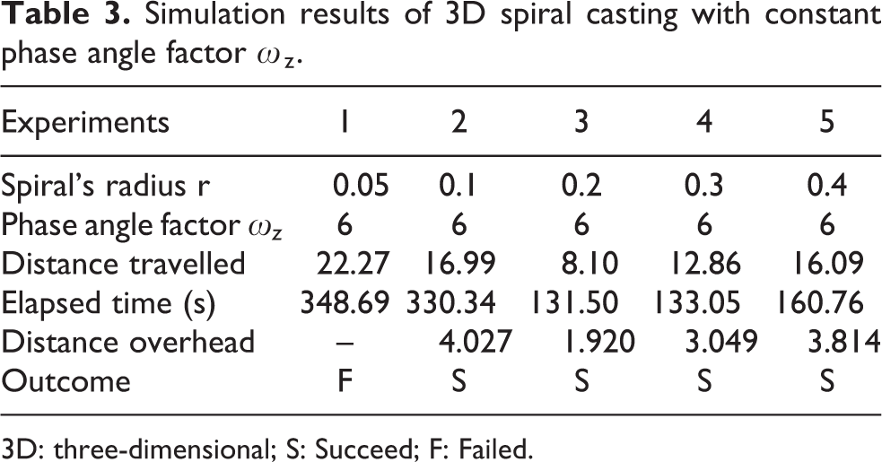
3D: three-dimensional; S: Succeed; F: Failed.
The impact of ωz is also investigated from 2 to 10 m at a constant spiral’s radius (ri) value of 0.2 m. Experiment 3 in Table 4 with the ωz value of 6 shows optimistic results with the shortest elapsed time and distance overhead. It can be noted that the under-assigned value of ωz has a high number of iterations for spiral casting; over-assigning would cause a large oscillation of the altitude (z-axis) per iteration.
Simulation results of 3D spiral casting with constant spiral’s radius r.

3D: three-dimensional; S: Succeed; F: Failed.
Lastly, the parameters for 3D zigzag casting and 3D spiral casting are tuned. Then, the performance between 3D zigzag casting, 3D spiral casting, and a combination of 3D spiral and zigzag casting are compared at different initial positions of the chemical source and the sniffer robot. We conducted a total of 1200 simulation tests (400 tests for each casting method: (1) 3D zigzag casting; (2) 3D spiral casting; and (3) the combination of both castings), with random initial positions of the sniffer robot. We categorized the random initial positions of sniffer robot into four different scenarios: scenario A, B, C, and D, as shown in Figure 21. The setting of scenario A is to locate 100 random initial positions of the sniffer robot in a region where it is at advantageous positions and near (short to middle range distance) to the down-stream plume Gaussian concentration dispersion model. As for scenario B, it is to randomly locate the sniffer robot in a region, where it is at advantageous positions but far (middle to long-range distance) from the plume source. Scenarios C and D are to randomly locate the initial positions of sniffer robot at the disadvantaged initial positions, beyond the down-stream chemical plume Gaussian concentration dispersion model. The only difference is that the sniffer robot is randomly located near to the plume source in scenario C, whereas the sniffer robot is randomly located far away from the plume source in scenario D.

Four different scenarios of the random initial positions of sniffer robots: Scenario A – advantageous positions and near to the down-stream plume propagation; scenario B – advantageous positions and far from the down-stream plume propagation; scenario C – disadvantageous positions and near to the down-stream plume propagation; scenario D – disadvantageous positions and far from the down-stream plume propagation.
As shown in Figures 22 and 23, in scenarios A and B, the sniffer robots were located at advantageous positions (on the down-stream chemical Gaussian concentration dispersion model). At these initial positions, 3D zigzag casting performs better in terms of both the elapsed time and the distance overhead as compared with 3D spiral casting, where around 32.42–56.37% better in distance overhead and around 14.93–28.97% better in terms of elapsed time. However, the success rate of the 3D spiral casting (100 and 99%) is better than 3D zigzag casting (97 and 69%) in scenarios A and B, respectively. Furthermore, in scenarios C and D, the robots were located at disadvantaged initial positions beyond the down-stream chemical plume Gaussian concentration dispersion model. The 3D zigzag casting failed in the CPT tasks, where zero percentage in both scenarios C and D. As for the 3D spiral casting, it has a success rate of 94 and 59% in scenarios C and D, respectively. It can be observed that the success rates for both methods are lowest in scenario D because the sniffer robot was located at disadvantaged initial positions, which is far away from the source and beyond the down-stream chemical plume Gaussian concentration dispersion model.

Simulation results of 3D zigzag casting at different initial positions. 3D: three-dimensional.

Simulation results of 3D spiral casting at different initial positions. 3D: three-dimensional.
Therefore, we can conclude that 3D zigzag casting has better efficiency when it is at an advantageous initial position near to the down-stream chemical plume Gaussian concentration dispersion model because this allows faster movement to discover the chemical plume near the surrounding. However, the 3D spiral shows higher efficiency in discovering far-off surroundings; hence, it would have better performance in terms of success rate. Apart from this, a disadvantaged initial position is when the robot is located upstream of the chemical plume; in such a case, 3D zigzag casting could fail because it does not support backwards casting. However, a 3D spiral does support backwards casting, and it would be able to complete the CPT tasks even at a disadvantaged initial position.
In the aspect of elapsed time, it is proportionate to the initial distance between the robot and the plume source. For instance, elapsed time of scenario B is higher than scenario A; and elapsed time of scenario D is higher than scenario C. However, one important observation that elapsed time of scenario B is higher than scenario C, even though the scenario C has bigger distance overhead than scenario B. There are two reasons for this attribution: first, scenario B has longer initial distance between the robot and the plume source than scenario C; second, scenario B has higher number of transitions from surge to casting stage, where the transitions consumed times during sensing sampling (see Figure 15).
The 3D CPT method could be improved by combining 3D zigzag and spiral casting. Both of these casting methods have their own advantages; spiral casting could be used for conditions in which there is a disadvantaged initial position or a long period of losing chemical tracks because it is a faster way to discover the new track. However, zigzag casting has better efficiency at the beginning of the scenario when track sensing is just lost or when it is at an advantaged initial position, which is a faster way to return to the chemical plume tracks. Figure 24 shows one of the scenarios of the 3D spiral-zigzag-casting CPT simulation.
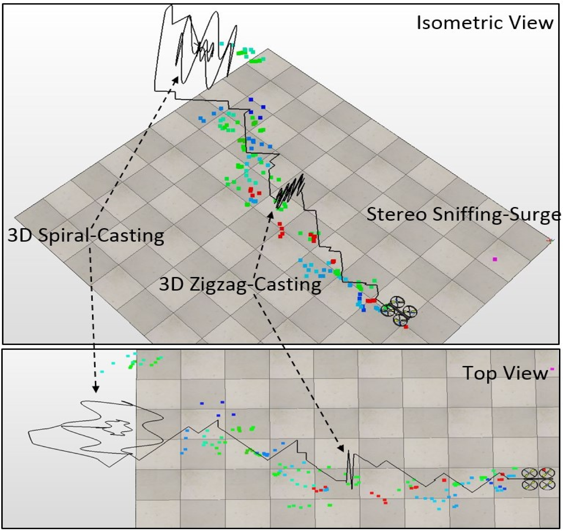
The illustration of 3D spiral-zigzag-casting CPT simulation (isometric- and top-view). 3D: three-dimensional; CPT: chemical plume tracing.
Figure 25 shows that 3D spiral-zigzag-casting CPT has higher success rate than 3D zigzag casting (where spiral-zigzag-casting CPT has 96% and 59% success rate in scenarios C and D, respectively, as compared to zigzag casting, which has zero percentage success in both scenarios C and D); because it can overcome the limitations of the 3D zigzag casting at a disadvantaged initial position. Besides, it has superior performance in terms of distance overhead and the elapsed time of 3D spiral because it inherits the advantage of the 3D zigzag of returning faster to the chemical plume when just beginning the out-tracing sensing scenario, around 3.42–15.25% in terms of distance overhead and 1.33–14.62% in terms of elapsed time.

Simulation results of 3D spiral-zigzag casting at different initial positions. 3D: three-dimensional.
Experimental platform and results
An experimental platform was developed, which involved a quadrotor with four gas sensors mounted below each propeller. A target coloured mark was pasted on the top for the image processing of the positioning system to specify the target, as shown in Figure 26. A multi-camera array was set up, and the image processing-based positioning system with the Kalman filter was developed, as shown in Figure 27. Figure 28 shows the graphical user interface that displays the wind information and the real-time trajectory path of the quadrotor, such as the direction and the speed. A chemical plume generator was developed by using the ultrasonic atomizing transducer to produce ethanol vapours, which releases its plume into 3D space, as shown in Figure 29.

The quadrotor that equipped with four gas sensors mounted below each propeller.

Multi-camera array image processing-based positioning system.
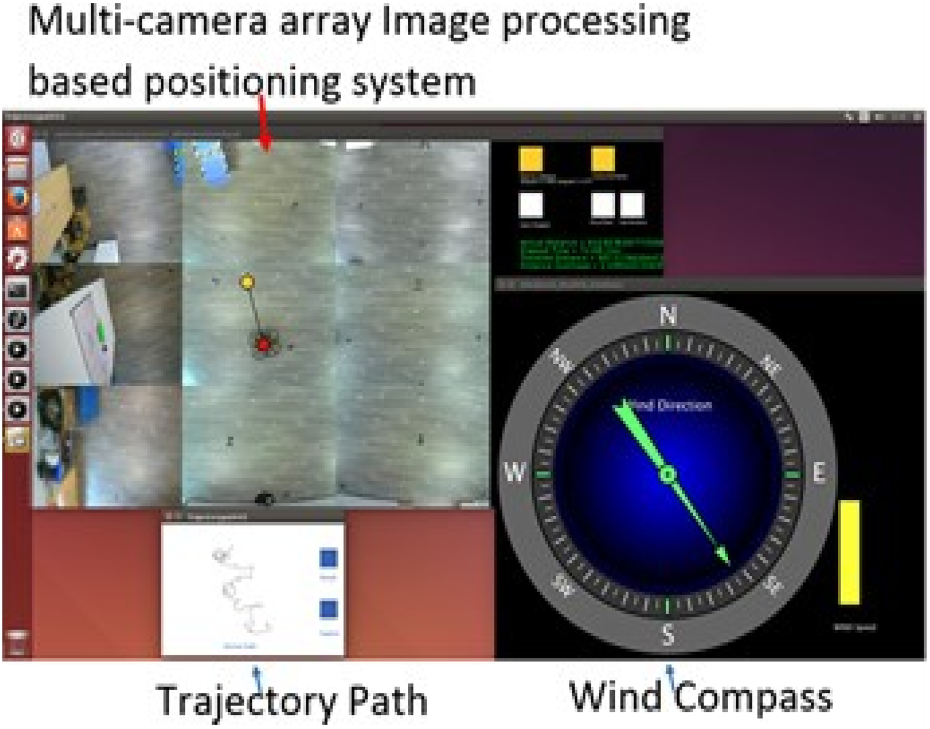
CPT control system user interface. CPT: chemical plume tracing.

Chemical plume generator.
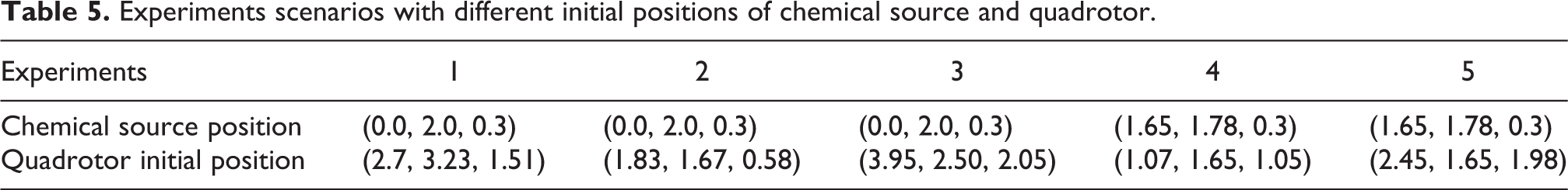
The experimental results obtained are shown in Figures 30 to 32 which compares with simulation results, under the same testing parameters. The chemical source and the quadrotors’ initial positions for both simulation and experiments tests are given in Table 5. The experimental results are consistent with the simulation results, although the experimental results have slightly poorer performance than simulations in terms of the distance overhead and the time elapsed. This is because the wind velocity in the simulation was ideal, which provided better stability than experimental conditions. However, in the real world, the environmental wind is hard to control.

Experimental results of 3D zigzag casting at different initial positions. 3D: three-dimensional.

Experimental results of 3D spiral casting at different initial positions. 3D: three-dimensional.

Experiment results of 3D spiral-zigzag casting at different initial positions. 3D: three-dimensional.
Experiments scenarios with different initial positions of chemical source and quadrotor.
Overall, the experimental results agreed with the simulation results by showing that 3D zigzag casting fails at disadvantaged initial positions when the robot is located beyond down-stream of the chemical source. This proves that 3D zigzag does not support backwards casting, as shown in Figure 30 – experiments 4 and 5. However, the 3D spiral does have backwards casting, and it would be able to complete the CPT tasks at disadvantaged initial positions, as shown in Figure 31 – experiments 4 and 5. The simulation and the experimental results both showed that the 3D spiral-zigzag-casting CPT exhibit better overall performance as compared with 3D zigzag casting and 3D spiral casting. The 3D spiral-zigzag-casting CPT has a higher success rate than 3D zigzag casting; it also shows better performance than 3D spiral casting in terms of the elapsed time and distance overhead, as shown in Figure 32.
Conclusion
In this study, we implemented a 3D CPT with a quadrotor and analysed its airflow. A certainty factor algorithm was developed to sense the in-track or out-track sensing scenarios and overcome the long recovery problem of MOX sensors. A fuzzy logic-based stereo-sniffing algorithm was also developed; it was incorporated into the quadrotor system, which enabled determination of the direction of the subsequent tracing step towards the chemical plume. A 3D spiral-zigzag casting with variations in the altitude (z-axis) was studied and its results were tested through both simulation and experiments. The results prove that the variation in the altitude (z-axis) during the casting stage is one of the key elements of a successful 3D CPT algorithm. As for future works, the impact of various environmental parameters on the performance of the algorithm will be studied, especially the one which involves the dynamic moving obstacles that change the airflow direction affecting the sniffing process.
Footnotes
Declaration of conflicting interests
The author(s) declared no potential conflicts of interest with respect to the research, authorship, and/or publication of this article.
Funding
The author(s) received no financial support for the research, authorship, and/or publication of this article.