
Abstract
Energy consumption has significant influence on the working time of soft robots in mobile applications. Fluidic soft actuators usually release pressurized fluid to environment in retraction motion, resulting in dissipation of considerable energy, especially when the actuators are operated frequently. This article mainly explores the potential and approaches of harvesting the energy released from the actuators. First, the strain energy and pressurized energy stored in fluidic soft actuators are modeled based on elastic mechanics. Then, taking soft fiber-reinforced bending actuators as case study, the stored energy is calculated and its parametric characteristics are presented. Finally, two energy harvesting schematics as well as dynamic models are proposed and evaluated using numerical analysis. The results show that the control performance of the energy harvesting system becomes worse because of increased damping effect and its energy harvesting efficiency is only 14.2% due to the losses of energy conversion. The energy harvesting system in pneumatic form is a little more complex. However, its control performance is close to the original system and its energy harvesting efficiency reaches about 44.1%.
Introduction
Soft robots have drawn growing research interests in recent years due to their inherent compliance and flexibility in comparison with traditional rigid robots. 1 They are manufactured using low-modulus materials such as silicone rubber and have deformable structures inspired by biological systems. Based on the biomimetic design, soft robots are endowed with abilities which allow safety and adaptive interactions with unpredictable environments, while rigid robots are typical operated in well-defined environments. These features make soft robots ideal candidates in a variety of applications including service robots, medical robots, rescue robots, and defense robots. 2
Fluidic soft actuation is an important type of actuation technique for soft robots. Pneumatic and hydraulic powered soft actuators have the advantages of lightweight, high power density, low material cost, and ease of fabrication. They usually comprise elastomer films which will be deformed when embedded channels are expanded by pressurized fluid. The channel structure can be classified as ribbed type, hollow type, and seamless pleated type. 3 In addition, inextensible layer and fiber are employed as auxiliary materials in some actuators to achieve certain actuation like bending or twisting. 4
Fluidic soft actuators are driven and controlled by fluidic power systems consisting of a series of pumps, valves, and sensors. The energy consumption of the power systems has significant influence on the working time of soft robots in mobile applications such as autonomous robots and wearable robots which are supplied by independent power source. It is noticed that the fluidic soft actuators generally release pressurized fluid to atmosphere or water tank in retraction motion. Thus, considerable energy is wasted when the actuators are used to perform frequent periodic motions such as walking, 5 grasping, 6 swimming, 7 and so on.
To make full use of power source, it is worth harvesting the energy released from fluidic soft actuators instead of exhausting to environment. Energy harvesting is an attractive technique for self-powered electronics and energy-efficient mechatronic systems. 8,9 There have been a large number of articles on this topic and herein some literatures about harvesting energy from repetitive motion of human limbs and fluidic actuators are introduced. Yeo et al. presented a miniaturized generator which can harvest the energy from upper limb pulling motion to improve human motion economy. 10 Donelan et al. developed a biomechanical energy harvester which generated electricity during human walking. 11 Energy harvesting from hydraulic actuators in retraction motion can be achieved by using either electrical generators or hydraulic accumulators. 12 –14 Luo et al. investigated the reutilization of exhausted air from pneumatic actuators by developing a hybrid pneumatic-electrical system for energy saving. 15 The above contributions provide valuable references to the energy harvesting of fluidic soft actuators; however, they cannot be directly applied to fluidic soft actuators of which the harvestable energy form is different.
Wehner et al. 16 and Wang and Ren 17 have proposed initial fluidic schematics which route released air back into the pumping system to realize energy harvesting from fluidic soft actuators in retraction motion. However, they just introduce the concept of harvesting energy for soft robotics and technical details such as the characteristics of stored energy and the dynamics of energy harvesting systems are not involved. To further improve this technique, it is necessary to carry out further investigation and comparison between different energy harvesting schemes.
In this article, the strain energy and pressurized energy stored in fluidic soft actuators are analyzed and modeled. Taking soft fiber-reinforced bending actuators as case study, the stored energy is calculated and its parametric characteristics are presented. Then, two energy harvesting schematics as well as dynamic models are proposed and evaluated using numerical analysis. Finally, some conclusions are drawn based on comparison and discussion.
Energy stored in fluidic soft actuators
General analysis
Figure 1 shows several typical structures of fluidic soft bending actuators. 3 Despite the variability in structures, their operating principles are universal. When the chambers in the actuators are filled with pressurized fluid, fluidic pressure generates stress in the elastomer films, causing the material to strain. Considering the top and bottom parts of the actuators have equal lengths, if the top part is strained due to pressurized fluid, but the bottom part is contained by an inextensible layer, then the actuators will bend. The actuator shown in Figure 1(a) is the ribbed type where ribs between channels can mitigate strain normal to the neutral axis. The pleated type actuator shown in Figure 1(b) is capable of bending to higher curvatures than other structures, but it is more complex to manufacture. The hollow type actuator shown in Figure 1(c) has the simplest structure and is robust against delamination under high pressure. However, it requires a considerable amount of input energy to expand the actuated channel radially. To constrain radial deformation, fibers can be arranged along the actuator length as shown in Figure 1(d).

Structures of fluidic soft bending actuators. (a) Ribbed type, (b) pleated type, (c) hollow type, and (d) hollow type with reinforced fiber.
Considering the quasi-static status, the energy stored in actuated fluidic soft actuators mainly consists of two parts which are the strain energy in the elastomer material and the pressurized energy in the fluid. Silicone rubber is commonly used in the fabrication of soft actuators. It can be modeled as an incompressible Neo-Hookean material and then the strain energy per volume can be expressed as 18

where G is the shear modulus of the silicone rubber, and I 1 is the first invariant related to the orthogonal stretches λ 1, λ 2, and λ 3 as

By integral calculation on the whole elastomer, the total strain energy can be obtained as
where Vs is the volume of the silicone rubber.
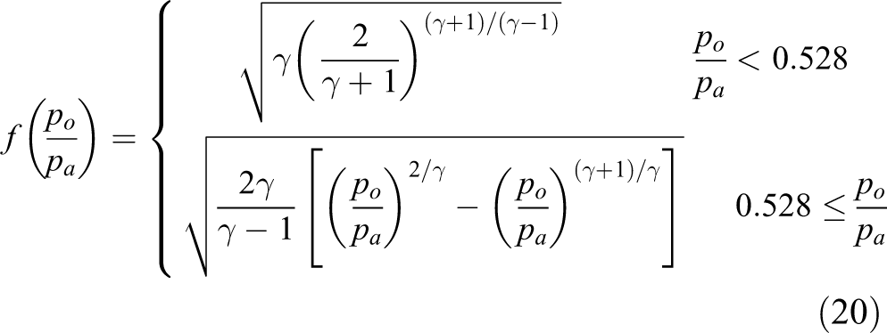
The fluidic drive can be either hydraulic or pneumatic. Soft actuators driven hydraulically usually require additional liquid tanks which are redundant for mobile application. Therefore, this study concentrates on soft actuators driven pneumatically where fluid can be obtained from the atmosphere directly. The release process of the pressurized air in the actuators can be regarded as adiabatic and described by using the following equation according to the ideal gas law

where pa and Va are the pressure and volume of the pressurized air, respectively, and γ is the specific heat ratio of air. The pressurized energy is equal to the work done when the air is released to the atmosphere and can be calculated as
where p atm is the atmosphere pressure. Then, the total energy stored in the fluidic soft actuators can be simply written as

Modeling of fiber-reinforced type
To further investigate the characteristics of stored energy, it is necessary to develop a detailed model with dimension parameters. There is no universal expressions because the actuators’ deformation characteristics are strongly dependent on their structures. In this study, the actuators with fiber-reinforced structure are taken as case study because they have much simpler tubular geometry that offers ease of manufacture, and where fibers are arranged along their length to avoid trivial deformation. Figure 2 shows the side view and the cross-sectional view, respectively, of a fiber-reinforced bending soft actuator, where L is the length of the inextensible layer which is also equal to the initial axial length of the actuator, θ and r are the angle and the radius corresponding to bending actuation, and a is the inner radius of the semicircular cross section. For convenience of modeling, the cross section is divided into top part and bottom part, of which the thicknesses of silicone rubber are denoted by t and b.

Fiber-reinforced bending soft actuator. (a) Side view and (b) cross-sectional view.
Since silicone rubber is effectively incompressible, its volume can be assumed as constant. In another word, the axial, the circumferential, and the radial stretches satisfy the relationship

The variation of the actuator’s radial size is negligible due to the fiber reinforcement constraint; therefore, the circumferential stretch is set as λ 2 = 1 and the following equation is obtained

Then, the strain energy density can be rewritten as

As shown in Figure 2, the axial stretch of the elastomer varies with the position on the cross section. At the bottom part, the axial stretch can be given by

where β is the variable along bottom thickness and varies between 0 and b. At the top part, the axial stretch can be given as

where τ is the variable along top thickness and varies between 0 and t, and φ is the variable related to polar angle and varies between 0 and π. Thus, the strain energy stored in the bottom part and the top part can be calculated by the following expressions

According to equation (5), the pressurized energy can be calculated once the fluidic pressure and volume corresponding to the bending angle are determined. The fluidic pressure has been modeled in literature 19 and can be expressed as

where Mb and Mt are the torques produced by the deformations of the bottom part and the top part, respectively, and their expressions are given as


The fluidic volume can be calculated as

Thus, the air pressurized energy can be obtained by substituting equations (14) to (17) into equation (5).
Characteristics
It is difficult to obtain analytical solutions for all the aforementioned integral calculations, so numerical method is employed to investigate the characteristics of the energy stored in the fluidic soft actuator. The shear modulus of the silicone rubber is set to 314 kPa in the calculations. 19 The nominal inner radius, length, and thickness of the studied actuator are 8 mm, 160 mm, and 2.5 mm, respectively. Figure 3 presents the air states and stored energy curves varying with bending angle. It can be seen that the air volume is almost linear with the bending angle and its variation only takes about 10% of the initial air volume when the bending angle reaches 360°. There is a little nonlinearity in the air pressure curve where the variation range is about 300 kPa. The total energy stored in the actuator is also linear with the bending angle. It is noticeable that the air pressurized energy is much more than the strain energy because of the air compressibility.
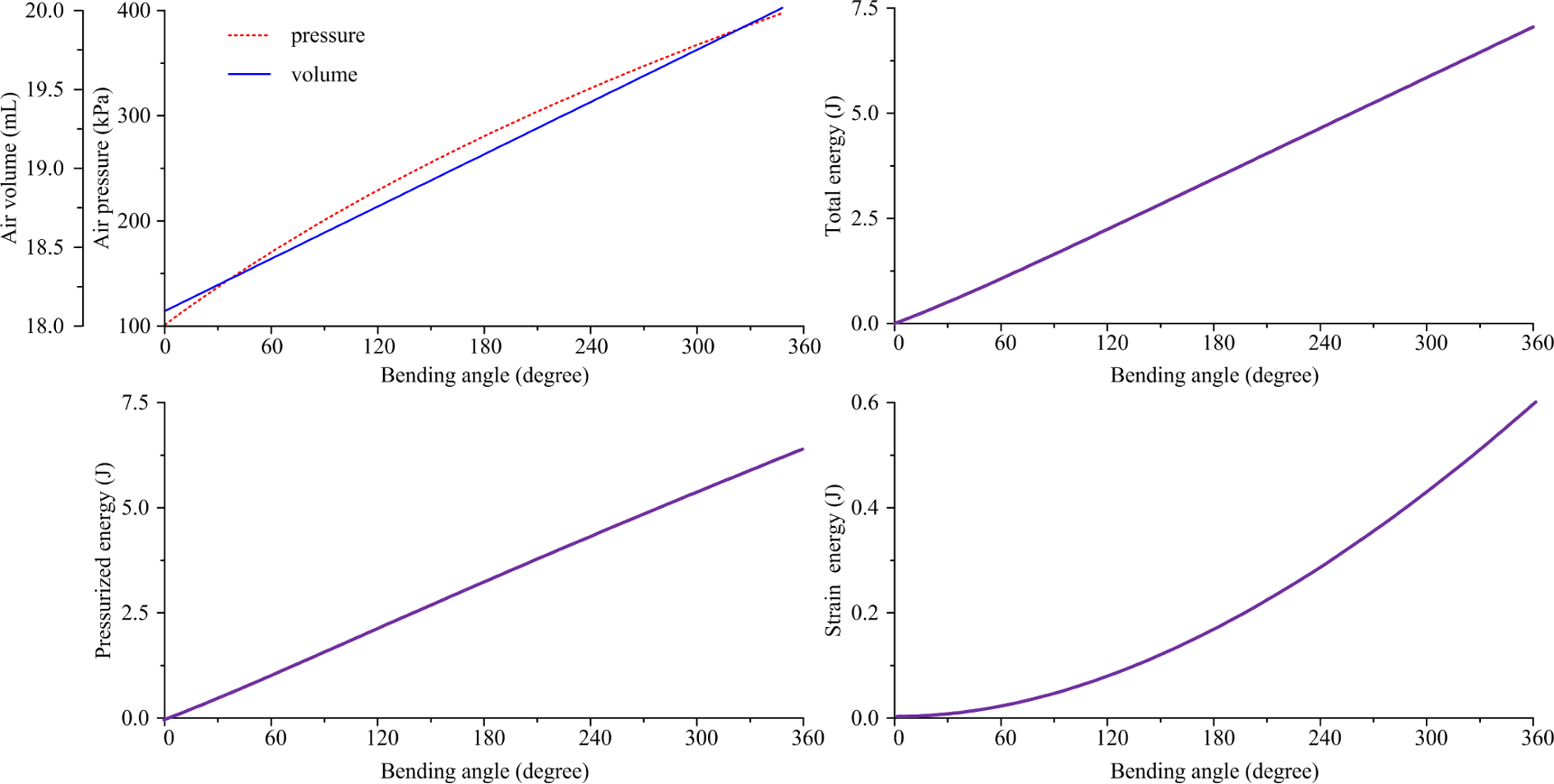
Air states and stored energy varying with bending angle.
Calculations with different dimensional parameters are also implemented in order to understand their effect on the total stored energy of fluidic soft actuators. It can be observed from Figure 4 that the stored energy becomes higher with the increase in the inner radius and the thickness of the actuator. However, the effect of the actuator length is relatively little in comparison with other dimensional parameters.

Effect of dimensional parameters on total stored energy.
Energy harvesting systems
Drive system without energy harvesting
In general, pneumatic soft robots in mobile applications can be driven by microcompressors, compressed fluid, and direct chemical reaction. The microcompressors are often the best choice for soft robots with relatively low pressure and flow rate because they provide the highest flow capacity in a commercial package. 16 Figure 5 shows a pneumatic drive system for fiber-reinforced fluidic soft actuators. When the actuator is extending, the microcompressor compresses air from the atmosphere and supplied energy in the form of pressurized air to the actuator. And when the actuator is retracting, the microcompressor stops running and the pressurized air in the actuator is directly released to the atmosphere. Two 2-position solenoid valves with pulse width modulation (PWM) are employed to govern the airflows through the charging and the discharging lines, respectively. It can be found that this drive system is not energy-efficient because the energy stored in the actuator is not well reutilized.

Drive system without energy harvesting for a fluidic soft actuator. (a) Extending motion and (b) retracting motion.
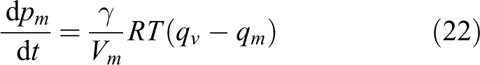
Then, the study focuses on the retracting motion as well as the air release process in which the air dynamics can be written as 20

where R is the universal gas constant, T is the air temperature, and qv is the mass flow rate through the 2-position solenoid valve. By using averaging approach, the air mass flow rate through the solenoid valve can be regarded as a function of control signal and pressures as 21

where
and uv is the PWM control signal of the solenoid valve, Cv is the valve flow rate coefficient, A is the effective valve area, and po is the valve outlet pressure which is equal to the atmosphere pressure as shown in Figure 5.
As analyzed in the “Energy stored in fluidic soft actuators” section, the bending angle of the soft actuator is a function of the pressure in the soft actuator. Therefore, the feedback of the actuator pressure is usually employed to realize closed-loop control and improve dynamic performance. 22 In this study, a proportional-integral controller is applied to regulate the actuator pressure during the retraction motion and the generated control signal of the solenoid valve is given as

where Kp and Ki are the proportional coefficient and the integral coefficient, respectively, and ep is the error between the target pressure and the practical pressure.
Energy harvesting in electrical form
Figure 6 presents the schematic of a pneumatic drive system with energy harvesting in electrical form. The basic principle is to install an energy harvester consisting a pneumatic motor and a coupled electrical generator in the air exhausting line. When the fluidic soft actuator is retracting, the pressurized air can drive the energy harvester and then generate electricity instead of releasing to the atmosphere directly. The generated electrical energy can either be supplied to attached electronics such as sensors or used to charge batteries.

Drive system with energy harvesting in electrical form. (a) Extending motion and (b) retracting motion.
In comparison with the system without energy harvesting, the system shown in Figure 6 has similar dynamics of the actuator and the valve; however, the outlet pressure of the valve is enhanced by the energy harvester rather than the atmosphere pressure. The pressure dynamics in the chamber from the valve outlet to the motor inlet can be given as
where pm and Vm are the pressure and volume of the chamber, respectively, and qm is the average mass flow rate through the pneumatic motor which can be expressed as
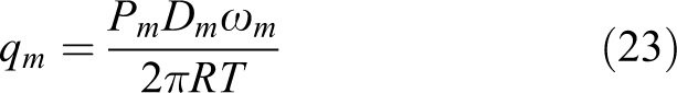
where Dm is the nominal displacement volume of the pneumatic motor and ωm is the angular velocity. The output mechanical torque of the pneumatic motor is given as

where ηm is the efficiency of the pneumatic motor considering the energy loss of pressurized air. Then, the rotor dynamics of the energy harvester is given as

where Tg is the electromagnetic torque induced by the electrical generator, Jt is the total moment of inertia, and Bm is the viscous frictional coefficient. It is assumed that the electrical generator is direct current (DC) type. Then, the electromagnetic torque can be written as

where Kt is the torque coefficient and ig is the generated current. In practical application, the generated electrical energy should be stored in a battery or a capacitor with the help of a converter circuit. In this study, it is assumed that the generated electrical energy is directly consumed by a resistive load in order to reduce the complexity of the system dynamics. The electrical dynamics in the generator can be described as
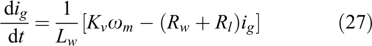
where Lw is the winding inductance of the generator, Kv is the electromotive force coefficient, Rw is the winding resistance of the generator, and Rl is the load resistance. The harvested energy in electrical form can be calculated as

The advantages of this energy harvesting method include simple configuration and convenience of energy reutilization. However, based on equations (22) to (27), it can be found that the harvesting mechanism has an equivalent damping effect on the system dynamics. When the actuator velocity (or the airflow rate) increases, the rotational speed, the electromotive force, and the DC current of the electrical generator will be increased accordingly. Then, the electromagnetic torque which is proportional to the DC current produces a larger resistive influence on the retraction motion.
Energy harvesting in pneumatic form
An alternative system shown in Figure 7 is to harvest the energy stored in the fluidic soft actuator by using an air tank. For retracting motion, the actuator energy flows to the air tank if the air pressure in the actuator is higher than in the air tank, otherwise the actuator energy directly exhausts to the atmosphere. A 3-position solenoid valve is employed to switch air circuit and regulate pressure. For extending motion, the microcompressor provides energy to the actuator with the auxiliary energy in the air tank. A 2-position solenoid valve is used to govern the connection between the microcompressor and the air tank according to the actuator motion mode. A check valve is installed to isolate the air tank and the atmosphere. When the pressure of the air tank is higher than the atmosphere pressure, the microcompressor will suck air from the air tank. When there exists some degrees of vacuum in the air tank, the check valve will be open and the microcompressor will suck air from the atmosphere. It is better to adopt a check valve with low cracking pressure so as to reduce the energy consumption on the valve.
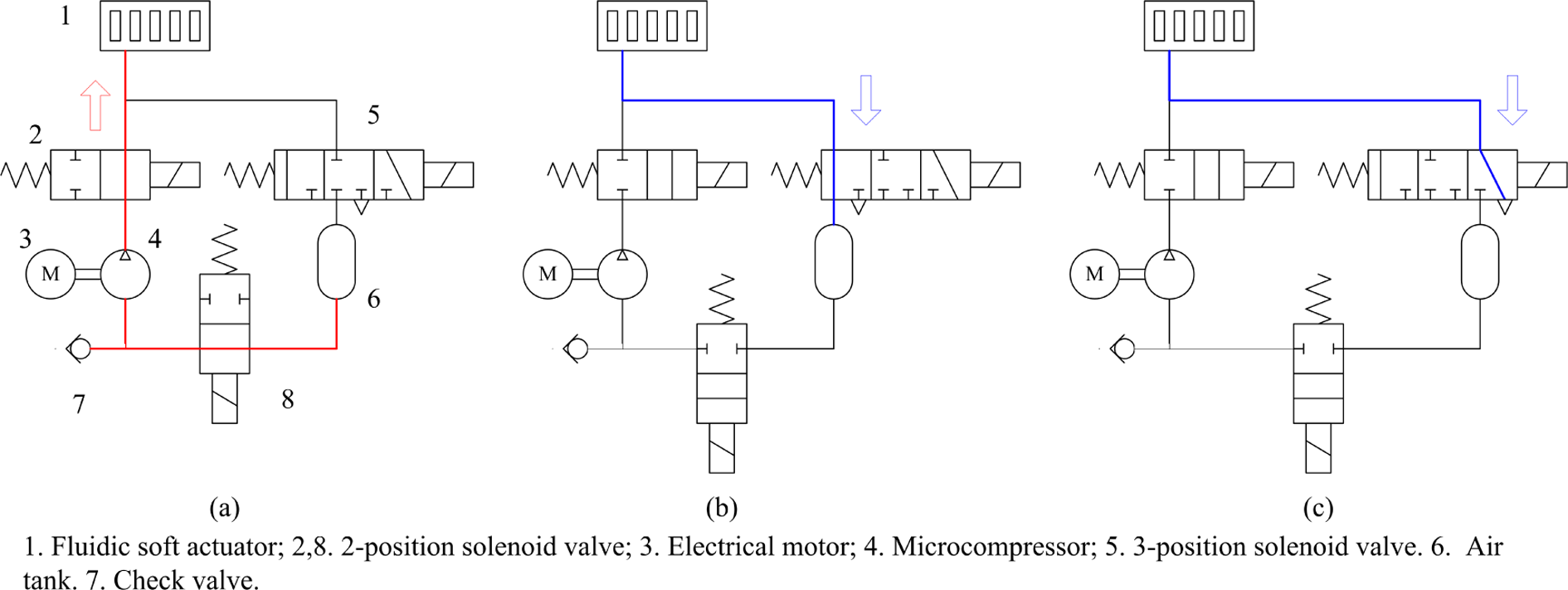
Drive system with energy harvesting in pneumatic form. (a) Extending motion, (b) retracting motion if actuator pressure is higher than air tank, and (c) retracting motion if actuator pressure is lower than air tank.
In comparison with the system without energy harvesting, the system shown in Figure 7 also has similar dynamic equations of the actuator and the valve. The difference mainly lies in the pressure variation of the air tank when the actuator is retracting. The pressure dynamics in the air tank can be given as

where pt and Vt are the pressure and volume of the air tank, respectively. When the pressures in the actuator and the air tank are equal, the harvested energy in pneumatic form can be calculated as

where pte is the quantity of the balanced pressure.
As there is no energy conversion in the harvesting process, this energy harvesting system has higher efficiency, and the harvested pressurized air can be used to boost the pneumatic power source. Its disadvantages include that more valves are required and the system structure is more complex.
Numerical analysis
To evaluate the proposed energy harvesting technique, simulations based on the dynamic models are implemented using MATLAB/Simulink software [version 2014]. The numerical analysis mainly concentrates on the retracting motion of the fluidic soft actuator as well as the energy harvesting performance. The original drive system, the system with electrical energy harvesting, and the system with pneumatic energy harvesting are all involved to make comparison and labeled as systems (1), (2), and (3), respectively, for convenience. The characteristics of the fluidic soft actuator are modeled as lookup tables which are precalculated in the “Energy stored in fluidic soft actuators” section. The bending angle varies from 360° to 0° in the retraction motion. Figure 8 shows the simulation model of the energy harvesting system in electrical form, where the dynamics of main components are packaged as submodules.

Simulation model of electrical energy harvesting system for fluidic soft actuator.
The parameters required in the numerical analysis are presented as follows. The specific heat ratio of air is 1.4, the universal gas constant is 287 J/kg/K, the atmosphere pressure is 1.013 × 10⁵ Pa, the valve flow rate coefficient is 0.06, the effective valve area is 3.8 × 10⁻⁶ m2, the proportional coefficient and the integral coefficient of the controller are 0.002 and 0.05, respectively, the chamber volume from the valve outlet to the pneumatic motor inlet is 1.5 mL, the nominal displacement volume of the pneumatic motor is 0.5 mL, the pneumatic motor efficiency regarding the pressurized loss is 0.65, the total moment of inertia is 1.8 × 10⁻⁶ kg·m2, and the viscous frictional coefficient is 3.2 × 10⁻⁶ Nm/(rad/s), the torque coefficient is 0.025 Nm/A, the electromotive force coefficient is 0.025 V/(rad/s), the winding inductance and resistance of the generator are 0.5 mH and 1.8 Ω, respectively, the load resistance is 20 Ω, and the air tank volume is 50 mL. Since the variation of air temperature is much slower in comparison with other state variables such as mass and pressure, it is assumed that the air temperature in the simulations keeps constant as 300 K.
Figure 9 presents the performances of pressure control and energy harvesting of the studied systems with step input and ramp input, respectively, which are effective to verify the systems’ dynamic response and tracking performance. It can be observed that system (1) which cannot harvest energy has the best control performance regarding response time and tracking error. The control performance of system (3) is close to system (1) except for some distortion in the step response, which is caused by valve switch. System (2) has the worst control performance especially when the actuator pressure becomes relatively low. The reason is that the electrical energy harvester induces a strong damping effect on the system dynamics.

Performances of pressure control and energy harvesting. (a) Step response and (b) ramp response.
In general, the energy consumption of power source is equal to the sum of the energy stored in soft actuators and the energy dissipated in meter-in solenoid valves. The latter is strongly dependent on microcompressors’ pressure-flow characteristics which vary with different machines. It is impossible to obtain a uniform ratio between the harvested energy and the energy consumption of power source. Therefore, this study chooses the ratio between the harvested energy and the energy stored in soft actuators as evaluating index. From the numerical results, it can be found that the energy amount harvested by system (2) is about 0.998 J, while system (3) is about 3.111 J, of which the ratios to the stored energy in the actuator are 14.2% and 44.1%.
The parametric effect on energy harvesting efficiency is also investigated. Figure 10 presents the energy harvested by system (2) with different load resistances. It can be seen the harvesting efficiency reaches optimal when the resistance is about 15 Ω. The limited variation range of the harvested energy shows that the load influence on system performance is not significant. Figure 11 presents the energy harvested by system (3) with different air tank volumes. From the curve, it can be observed that the harvesting efficiency increases with the increase in air tank volume and tend to saturate when large volume is employed. A tank volume of 50 mL is a trade-off design considering both energy efficiency and installation space. Despite a more complex configuration, the energy harvesting system in pneumatic form is advantageous on the whole in comparison with the system in electrical form.
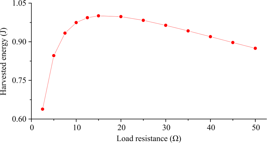
Energy harvested by system (2) with different load resistances.

Energy harvested by system (3) with different air tank volumes.
Conclusion
This article mainly explores the potential and approaches of harvesting the energy released from fluidic soft actuator. Based on modeling and numerical analysis, the following conclusions can be drawn. First, according to the developed model, it is found that the energy stored in the fluidic soft actuator is considerable and approximately linear with the bending angle. The actuator’s inner radius and thickness have positive effects on the stored energy, but the length has little effect. Second, an energy harvesting system in electrical form is proposed by installing a pneumatic motor and an electrical generator in the air exhausting line. The results show that the system has bad control performance because of increased damping effect and its energy harvesting efficiency is only 14.2% due to energy conversion. Third, an energy harvesting system in pneumatic form is a little more complex. However, its control performance is close to the system without energy harvesting and its energy harvesting efficiency reaches about 44.1%. It is advantageous on the whole compared with another energy harvesting approach. In future, experiments with various conditions will be implemented to investigate the proposed energy-saving systems.
Footnotes
Declaration of conflicting interests
The author(s) declared no potential conflicts of interest with respect to the research, authorship, and/or publication of this article.
Funding
The author(s) disclosed receipt of the following financial support for the research, authorship, and/or publication of this article: This work was supported in part by the National Natural Science Foundation of China (grant no. 51405147), the Natural Science Foundation of Zhejiang Province (grant no. LY18E090001), the Cooperation Program between Zhoushan City and Zhejiang University (grant no. 2017C82217), the Project of Key Innovation Team of Zhejiang Province (grant no. 2013TD14), the Natural Science Foundation of Hunan Province, China (grant no. 2015JJ3041), and the Fundamental Research Funds for the Central Universities.