
Abstract
The article presents the design and application of multi-software platform for solving kinematic synthesis of robot manipulator systems. It also presents a modern theoretical and application approach for modelling coupled mechanical systems, which include mobile robots. Due to high requirements for accuracy, efficiency, reliability and life cycle of technical equipment, several parameters ensuring optimal operating parameters need to be taken into account while dealing with the design. This is the reason for linking computational models to optimization algorithms that allows us to find the appropriate design parameters of analysed mechanical system, mechanisms, including mobile robots mostly by iterative way. The commercial working interface of the program ADAMS and open architecture of MATLAB programming language enable to share common data while dealing with model simulations in parallel. Both of them were used while designing and implementing the algorithm for the evaluation and optimization of parameters of technical equipment from the point of view of selected properties. While working on the task of the spatial mechanism of the six-member robot manipulator system, the algorithm solving the optimal parameters was created by applying the selected optimization techniques of the program MATLAB. Presented algorithm involves the creation of a map operating positions, which is further linked to the solution of the motion of interest points in the robotic system following a prescribed trajectory. This requires the geometry optimization of the selected members of the spatial robotic system in order to achieve such parameters so that the trajectory of the interest point of the output member would precisely match with the prescribed trajectory. It is important to note that these types of tasks create wider space for solving the assignments dealing with the development and application of technical equipment like mobile robots and their outputs that are linked to the needs of the practice.
Introduction
The current solution to the problems of the industrial automation production is bound up with powerful computers and efficient algorithms that can solve very complex synthesis problems of robots with different purposes. In other words, demanding engineering tasks can be solved thanks to the development of algorithm numerical procedures and computer efficiency. In the past, the solution to the problems of kinematics and dynamics of robotic systems was based on the principles of analytical mechanics. The first applications of the dynamics of rigid bodies are related to gyrodynamics, mechanism theory and biomechanics. 1 However, requirements for more complex models and a rapid hardware as well as software development of computers lead to the development of a new branch dealing with mechanical problems of coupled mechanical system (CMS). Results of classical mechanics were extended to computer algorithms, which deal with the multibody formalisms. One of the first formalisms was created by Hooker and Margulies 2 in 1965. This approach was developed for satellites consisting of an arbitrary number of rigid bodies interconnected by spherical joints. Another formalism was published by Roberson and Wittenburg. 3 In 1980, software systems for the modelling, simulation and animation as described by Schwertassek and Roberson were offered on the market. 4 The next step forward in flexible multibody systems was documented by Shabana. 5,6 In 2006, Bachau 7 considered computational multibody dynamics (MBD) approaches including impact problems.
The following section reviews chosen works that can be considered as beneficial for discussed branch of mechanics. Lederer 8,9 deals with the usage of optimization methods in the synthesis of mechanisms in his works from 1988 to 1989. He presented different optimization methods in the synthesis of CMS from a mathematical perspective. At the same time, he deals with the synthesis of mechanisms using methods which do not exploit the mathematical methods of optimization. Brat 10 devotes his work from 1981 to matrix methods in the analysis and synthesis of spatial CMS, in which the kinematic analysis is described in detail whereas dynamic analysis is discussed in abbreviated form. The application of optimization algorithms in the mechanics of bodies is discussed in the work of Saga, 11 in which he summarized the optimization methods and presented practical examples from the mechanics of flexible bodies. The useful information can be found here as he reflected CMS with the elastic members. A valuable chapter dealing with the genetic algorithm, the usage of which is demonstrated by practical examples, can be found in the book written by Bocko and Delyova. 12 Complex synthesis procedure of the guidance CMS is described by Jensen and Hansen 13 in his article. He devotes a special attention to the issue called ‘Non-Assembly’, where the algorithm enumerates the target function for different dimensional configurations of CMS. Then, Lederer et al. 14 in his scholarly text investigate the usage of higher order derivatives in design of crank and cam CMS. Martínez-Alfaro 15 presented the usage of simulated annealing algorithm in the synthesis of CMS so that a specific path point described the trajectory through a given set of n points as accurately as possible. The evaluation is carried out by using probabilistic methods. In Hansen’s article, 16 one can follow three ways of synthesis of CMS. To be more specific, the change of geometry depending on the trajectory, the replacement of some members by the spring and damping device, and finally, the method of synthesis, which enables conditions of ‘Non-Assembly’, which do not allow the mechanism to assemble dimensionally. Kim et al. 17 presents a method of topology automated synthesis of planar mechanism, which is composed of tie rods. The stiffness of the springs of the individual blocks of the system is compared and then they are joined by rotary or rigid link, or they are disconnected. Optimal topology of CMS is obtained by this iterative procedure. Yang et al.’s work 18 deals with the implementation of numerical methods and their algorithms into the programming environment of MATLAB. The most applicable chapters are those, which deal with the optimization and solution of the system of nonlinear and differential equations. The book written by Fletcher 19 is dedicated to clarifying the basic principles of the optimization methods, which provides insights into their derivations and proofs. Numerical tests of the methods and comparison of their efficiency are very beneficial. Moreover, the author of this book is one of the founders of commonly used Broyden–Fletcher–Goldfarb–Shanno methods, which are fully described and compared with other methods of optimization without constraints.
Therefore, software packages based on the principles of MBD are currently applied for the kinematic and dynamic analysis of manipulators – robot arms, vehicle and mobile robots. They deal with solving flexible CMS, contact problems, impact problems, optimization of mechanical systems with applications to machinery, vehicle dynamics, robotics, and they even address biomechanical issues and more. Designing mechatronic systems requires the development of multiphysical simulation models and how to manage them. Both of these areas develop rapidly. Valasek 20 in his article develops the concept of mechatronic system, methods for simulation model development, methods of model management and he also provides the examples of mechatronic systems in automotive applications.
Researchers continue with the intensive development and research of parallel and hybrid kinematic structures in the fields, such as mechanics and mechatronics, automation and robotics. As a result, we currently have a lot of knowledge and technologies that allow us to develop and explore these areas efficiently. 21 Modern applied mechanics of multibody systems is characterized by systems consisting of mechanical, electrical and hydraulic components, which are currently controlled by the control elements. Algorithms of the intelligent management along with other elements of the technical intelligence, such as sensors and actuators, can cope with incorrect and also insufficient inputs during unexpected and non-standard situations. Developing the algorithms of self-regulation, learning and generally acquired knowledge are needed for intelligent management, and therefore, we use apart from modern numerical methods also the combination of the strengths of the artificial intelligence techniques, including expert systems, neural networks, fuzzy logic and genetic algorithms. 22
Theoretical aspects of kinematics and mechanical systems optimization
Kinematic solution of CMS
The kinematic solution while dealing with the tasks of CMS is necessary and often very difficult phase, for example, when assessing the accuracy and sensitivity of their activities, solving dynamic problems, kinematic and dynamic synthesis, while analysing stress or dealing with optimization tasks, and so on. Therefore, main task of kinematic analysis is to describe the kinematic quantities of any CMS depending on the time, if the movement in the driving members is known while at the same time the structure of the kinematic chain and geometric parameters of its members are known.
As a result, the kinematic description of CMS, under which we understand the choice of coordinates and their types, has a considerable impact on the complexity and speed of the solution. 23
However, one should keep in mind that each solution of kinematic and dynamic of CMS can be based on several approaches. For the kinematic description of planar system CMS, we use trigonometric method, vector method, complex numbers method and matrix methods. For spatial CMS, we use the same methods as with planar system plus we use Euler parameters (quaternions) for spherical movement, 24 using number of rotation and more. Each method has its advantages and disadvantages. From the overview of the works devoted to kinematics of spatial and planar CMS, it is evident that most of the current authors prefer the vector or various modifications of matrix methods.
Description of CMS via constraint equations
Let us describe briefly an onward applied approach of the vector method to formulate and to solve kinematic equations of CMS on the level in which constraint equations are formed by the method of complementary bonds. 24 Examples stated in the publication 24 are to lead to a construction of a systematic method for formulation as well as for solution of kinematic equations which is further solved by a suitable software package.
The basis of the stated methodology is formed by strong nonlinear algebraic spatial equations that must be derived to be equivalent with physical bonds. Constraint equations are not only derived from geometry of joints but they also must contain it.
A set of variables that specifies a position and a configuration of all bodies in CMS, that is, a configuration of mechanism is composed by generalized coordinates (Figure 1). These may be free or lock-up and they are required to meet the equation of constraint.
Let us define generalized coordinates by means of the column vector
When conditions of mutual movements between pairs of bodies are expressed as algebraic equations, which account generalized coordinates, these equations are termed as holonomic kinematic constraints. The system of nh holonomic equations that are not dependent upon time, that is, they are scleronomic, can be expressed by equations of geometric bonds

In case of time-dependent kinematic relations, it is the equation of kinematic bond

When time t does not explicitly enter into the equation of geometric bond, as in the case of equation (1), the bond is termed as stationary (scleronomous). Bonds specified by equations in the shape of equation (2) are dependent upon time (reonomous). Equations that contain a relation between elements of velocity are termed as non-holonomic (a function is not an integrated function of velocity).
In the article, we assume that holonomic bonds are most frequent in technical practice.
The mathematical model does not define a motion of system if kinematic constraints do not include inherently equations of geometric and kinematic bonds. This is further clarified as follows:
If n′ > nh, then a number of equations of geometric bonds (1) or (2) are not sufficient to solve

To set up a motion of system, a calculator must define the following: additional kinematic conditions that define forces that act on the system, in this case,
If DOFs of independent kinematic bonds for kinematic analysis are specified and formulated as

then a configuration of the system can be defined as a function of time, that is, constraints (2) and (3) can be written into one matrix in which n from generalized coordinate figures

Positional analysis
Kinematic equations provide an analytical basis for an analysis of a position, velocity and acceleration. In this paragraph, we state forms of writing of equations of position, velocity, acceleration and a possibility to control a formulation of equations of positions of planar CMS. Geometric bonds provide with a definition which takes a function of a system into account. For a corresponding system, they may be formulated in the following matrix

where
Active bonds can be formulated as follows

We assume that a number of active equations in (6) are the same as a number of DOF of CMS and nh + DOF = n′. That is why equations (5) and (6) contain n′ equations in case n′ generalized coordinates.
Equations of geometric (5) and kinematic (6) bonds form a following system of kinematic equations

A task of an analysis of a position is to solve the vector

For a solution is important the following rule:
The theorem of the implicit function says that since the function
The basic method which is applied for a solution of nonlinear equations (7) is the Newton–Raphson method and its modifications. It is an iterative method which starts with the initial estimate

The estimate of the solution in the next step will be

Let us mention that the convergence of the Newton–Raphson method is quadratic and for an incorrect estimate of the initial approximation the method diverges. The method also diverges in case there does not exist any solution.
Modifications of the Newton–Raphson method strive to remove its two main deficiencies: to secure global convergence and to reduce demands on a calculating period.
If the Newton–Raphson method does not converge or the Jacobian is singular, an estimate of the initial approximation is incorrect (a given mechanism is not possible to construct).
To define the initial configuration, it is possible to use optimization techniques that enable us to find a better approximation of the initial configuration of the mechanism. The final function for minimization can be as follows
24

The vector
Velocity analysis
Assuming that the Jacobian matrix (8) is regular, and then, the stated theorem of the implicit function secures that there exists velocity and acceleration of the system.
By derivation (7), we obtain the equation of acceleration

Acceleration analysis
By means of the further derivation (12), we obtain equations of acceleration

It is exactly as in the case of the equation of velocity, the right side of the equation of acceleration can be formulated by the application of right sides of equations of acceleration for bonds defined in the work of Haug 24 (chapters 4.2 up to 4.5). Let us mention that the Jacobian matrix occurs in the equation of velocity as well as in the analysis of acceleration.
Application principles of optimization in robotic systems geometry draft
In the case of the structural optimization of mechanisms (robotic systems), we usually follow several stages. Let us try to define these stages as a methodological tool for realization of a calculating process that we performed and we present in the next chapter. Authors propose to follow the following procedure when solving optimization tasks 11,12 :
Step 1: To understand environmental conditions and the factor of expediency. Conditions under which the analysed CMS will serve its purpose are environmental conditions. Factors of expediency are agents according to which it is possible to evaluate whether a given mechanism is capable to serve its purpose.
Step 2: To establish criteria to determine optimum. We look for agents according to which we may evaluate quality of the robotic system (it can be, e.g., accuracy of movement – a prescribed trajectory). In case the agent of quality reaches extreme, we speak of gaining of the optimum state.
Step 3: To specify geometry and to establish draft variables. This stage of the draft is the most complex from the standpoint of the analytical procedure. A constructor uses a capability to forecast behaviour of various parameters in a specified operation of a robot and his previous experience with a similar proposed issue to synthesize construction parameters.
Step 4: To establish additional conditions. When we suppose draft variables in a task entering the axis n-dimensional space, then every point in this ‘draft space’ represents a draft that needs to be considered. A question which of the two points represents a better draft may be answered after appointment of valid coordinates into a target function and after a comparison of its values. The comparison has the point only then when the stated points represent an acceptable draft. The draft point is acceptable unless, in the case of environmental conditions, one of basic limiting states takes place, for example, to obtain the stress limit, a critical deviation in trajectory and so on. This condition is defined by the system of inequalities that express that the actual solution exceeds the prescribed values in no subsystem.
Step 5: To set up a mathematical model of a physically simplified technical task and mathematically correctly described optimization task, that is

In the case of a synthesis of robotic systems, the most frequent target function represents a mathematical description of kinematics of some of members. In our case, the target function is set as a sum of squares of discrete differences between points of a prescribed and simulated trajectory of the point of interest. Additional conditions may be additional equations, acceleration demands or acceleration in selected points and, last but not least, limit values of proposed variables.
Step 6: To select a suitable mathematical optimization method and to formalize an extremum task. Methods of optimization quite frequently vary, not only from a standpoint of basic principles and numerics, but also in efficiency in various applications. Each method requires a formalized extremum task to a certain extend which is described generally. However, it is not possible to formalize in an arbitrary way and to apply an arbitrary optimization algorithm. Every technical problem is described by its own superspace of optimization variables and mathematical qualities of the solved mathematical model. In the past, local searching algorithm based in simple iteration procedures was applied (Nelder–Mead, gradient approach, etc.) At present, based on genetic algorithms, as a member of the family of evolutionary searching approaches, it is possible to find a global extremum which is significant for a solution of an optimized draft of construction parameters of robotic system of various applications. Hybrid algorithms (e.g., memetic) use a regulated combination of different methods of optimization 25,26,28,29 according to their actual efficiency are now in the spotlight in an application in the sphere of optimization of mechanical systems.
Step 7: A mathematical solution of a formalized extreme task. In this stage of the draft, there takes place a mathematical processing and solution (the most frequently a numeric one) of formalized task of optimization. A procedure of the processing depends on a formulation of the task on a large scale and a selected method of a solution. 27,28
Step 8: A technical interpretation of the obtained solution. It is obvious that the final solution of the optimized task is necessary to ‘formulate into a language of engineers’ and to prepare for a practical application.
Robotic system structural optimization by application of multi-software approach
The solution to the synthesis of robotic devices is to find a suitable structure – geometry and corresponding suitable parameters of the mechanism (machine dimensions, geometry and cross-section, material, control algorithms, etc.) that meet certain functional and technological requirements. 29 These requirements may, for example, apply only to the position of mechanism parts or elements. In this case, we refer to geometric synthesis. 11,12,30 In other cases, we need to address speed and acceleration requirements. The methods that address these issues are the subject of kinematic synthesis. Dynamic requirements (balancing, reduction of reaction forces, reduction of operating irregularity, required operation characteristics, etc.) are addressed by dynamic synthesis.
The issue of mechanism synthesis was primarily characterized as a relationship between input and output (1:1). However, for mechatronic devices, the issue is quite complicated. It covers the entire area of mechanics and control. Solutions can be characterized by a greater number of inputs and outputs. Here arises the need to extend the techniques of traditional mechanics by techniques based on the theory of general design. 30
The article presents the original numerical approach to the solution of kinematic synthesis of mechanisms with the application and connection of the robust ADAMS system with mathematical tools of a high-level programming language MATLAB, expanding the possibilities to investigate the impact of changing multiple parameters on the solved system of fixed objects.
The aim of the solution is to create a map of operational positions of points of interest and to optimize selected virtual prototype parameters (operating device of the mobile machine) in such manner that the point of interest within its working cycle follows the prescribed trajectory as accurately as possible.
Figure 2 shows the kinematic scheme of the investigated device, which describes its five DOFs and point of interest ‘A’. Figure 3 presents a complex virtual prototype of the presented operating robotic arm of the mobile machine.

Planar Cartesian generalized coordinates of the body.
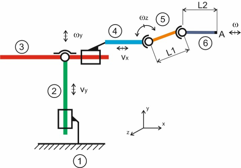
Kinematic scheme for a robotic arm of a mobile machine.

Virtual prototype with ADAMS/View software [Version ADAMS 2013.2].
Flowchart of geometric optimization.
We mainly address the so-called inverse kinematic task, that is, we search for appropriate design parameters of the system to achieve the prescribed motion of the point of interest.
23
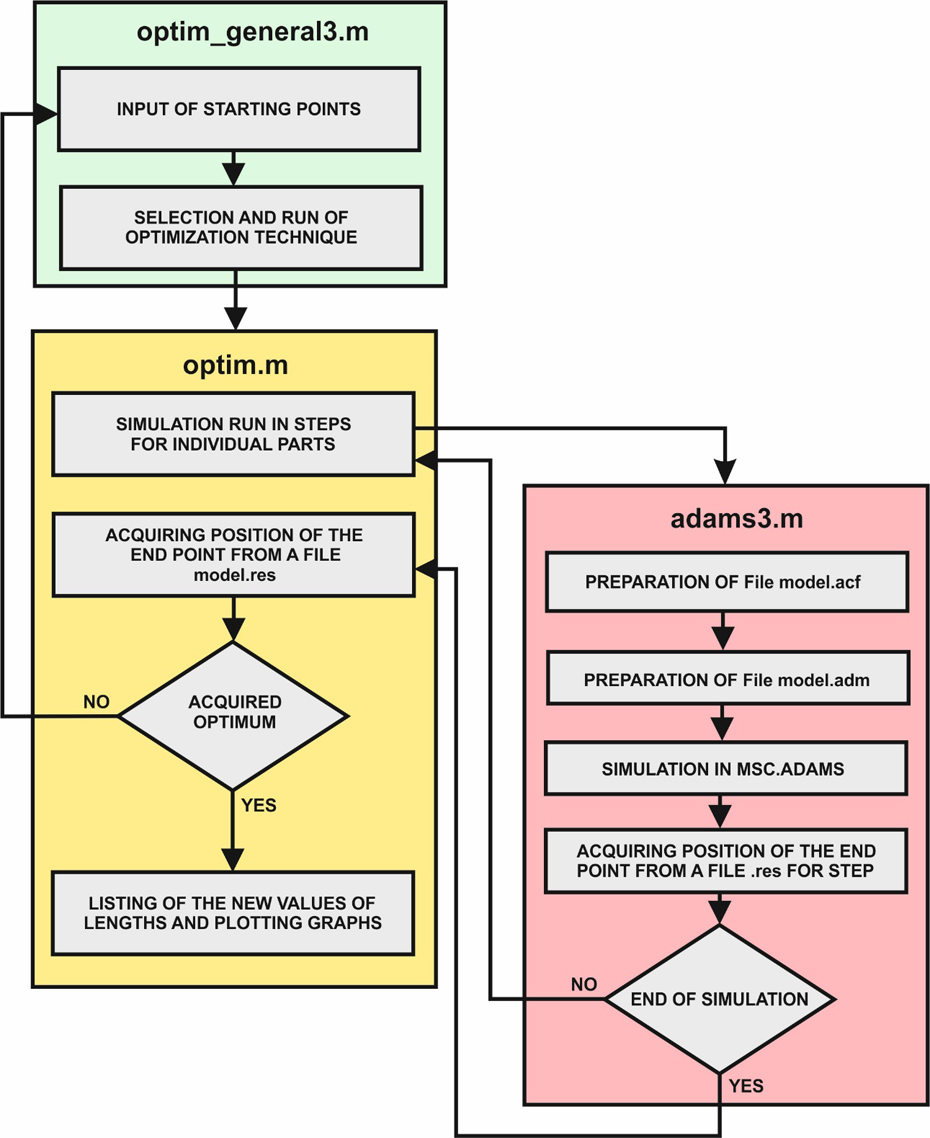
In order to achieve the prescribed motion, we will use a connection of text documents (.adm, .acf and .res files) of the MSC.ADAMS program addressing kinematics of the system with text environment of the MATLAB program, which control the optimization and evaluation process. For example, we briefly describe the main files created in MATLAB to perform the specified analyses: optimim_general3.m – in the file – there are defined starting points for the performance of optimization process and it also includes a selection of applicable optimization algorithms with definition of the file to calculate the target function (optim.m). optim.m – the file includes the definition of a progress of the motion in steps, representing a calculation of the target function, that is, the minimum distance of a point from the prescribed trajectory and drawing of a map of the ‘A’ point of interest locations; the program further cooperates with the file adams3.m, where the results of kinematic analysis are processed (ADAMS). adams3.m – loads template.adm file, creates files model.acf and model.adm, runs MSC.ADAMS program and opens the result file model.res.
The final structure of the described calculation procedure is shown in Figure 4.
The file created in MATLAB contains commands that amend the input parameters of the kinematic mechanism (shifts and angular rotations) and optimization variables (geometry of CMS parts). The prescribed trajectory was a curve (screw line) created by quadratic interpolation through previously defined points (see Figure 5). Assuming the use of stepper motor with a step of 5 mm and five levels, a map of operating positions (coordinates) of the end point ‘A’ was generated (see Figure 6).

The definition of the prescribed trajectory of the point of the interest of the mechanism.

The map of the operational positions of points of interest of the robotic arm.
In the next step, a map of operating positions around the prescribed trajectory was created and points nearest to it were looked up (see Figure 7). The detail is shown in Figure 8.
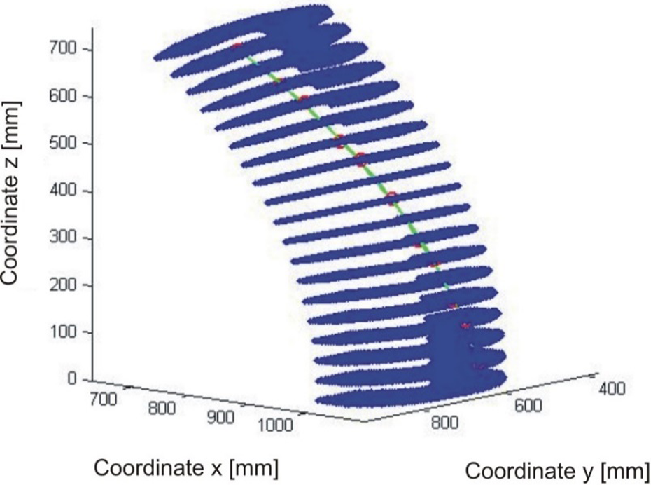
The map of the operational positions, trajectory and the nearest points to it.

The map of the operational positions detail – the nearest points to the trajectory.
The points nearest to the prescribed trajectory were selected from the map of operating values. Therefore, in order for the motion of the ‘A’ end point of the selected mechanism to follow the prescribed trajectory even more accurately, the optimization of lengths of the selected parts of the mechanism was performed. The solution procedure was as follows: A map of operating positions of the ‘A’ point of interest contains n points, that is, positions of ‘A’ point when moving along the followed k
1 trajectory.
n fixed points were defined on the prescribed k
2 trajectory – required positions of the monitored point. Nearest points of both trajectories were selected from the map of operating positions, based on minimizing criterion (target) function defined as a quadratic function of coordinates variances, that is

where


where

History of iterative process.
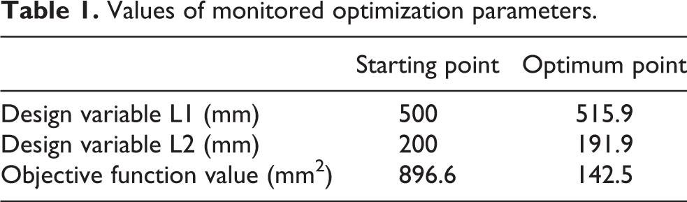
The search process has ended when that the relative change of target value reached less than ε = 1 × 10⁻⁴. The result of the solution (see Table 1) was values of selected geometric parameters L1 = 515.9 mm and L2 = 191.9 mm (see Figures 10 and 11).
Values of monitored optimization parameters.

Iteration process history for the length L1.

Iteration process history for the length L2.
Discussion
The article presents a design and performance of the original approach of a multi-software solution for the optimization of mobile robotic systems. Research on trajectory optimization, planning and control of industrial robots has an important practical relevance for improving their operating performance. It has to be noted that the correcting optimization of the prescribed trajectory is necessary, because the work tool path needs to be performed without any restrictions with regard to not only the quality of the implemented technology, but also to the mechanical damage caused by strain in the structure of the manipulator industrial robot. The application of theoretical procedures was performed on a six-part calculation model of a spatial robotic arm, with five DOFs, the configuration of which has a real basis in industrial production. The solution algorithm of optimum kinematic parameters was performed by applying the specialized software in MATLAB created by the authors, with a connection to the commercial software package for the solution of MSC.ADAMS object systems dynamics. Solving the issue has highlighted the possibilities of implementing optimization algorithms such as from MATLAB to a common configuration with ADAMS software package; in addition, the algorithm for solving the synthesis of its kinematic parameters was tested on an example of six-part robotic arm with the application of a selected optimization algorithm from the environment of MATLAB language. An important aspect is the fact that the proposed methodology will also confirm the selection of an appropriate kinematic virtual prototype topology. It can also be used for special application tasks, where the development of modularity and subsequent reconfiguration of these mechanisms is considered. Ultimately, this approach was verified in a simulation environment, the mathematical apparatus of which allows solution not only with regard to kinematic but also to dynamic parameters of the proposed and optimized virtual prototype.
Footnotes
Declaration of conflicting interests
The authors declared no potential conflicts of interest with respect to the research, authorship, and/or publication of this article.
Funding
The author(s) disclosed receipt of the following financial support for the research, authorship, and/or publication of this article: The work has been accomplished under research projects nos VEGA 1/0795/16 ‘Development of effective methods for correction and optimization of coupled mechanical systems’ and KEGA 015ŽU-4/2017 ‘Advanced computational and experimental tools and their implementation into new study programs of mechanical engineering’.