
Abstract
Haptic devices have been highly valued in virtual training environments in the medical field. Nevertheless, the principal challenges to develop these environments are the complexity to model the virtual elements and to provide proper haptic feedback during tasks. In this study, it was decided to take advantage of NVIDIA PhysX physics engine to produce a fast and effortless process in the creation of a virtual training environment for suturing tasks. Although PhysX correctly deploys collisions between solid and deformable objects in the graphical environment, it does not send this information to the developers environment to provide haptic rendering. Therefore, in this article, a “simplified method” was proposed to facilitate the detection of collisions between rigid and deformable bodies. This simplified method allows the calculation of haptic feedback to be displayed, and it avoids complexity and high computational costs. Additionally, an architecture to facilitate the integration of haptic devices was designed. The study case proposed in this work was the development of an application to perform a suturing task, SutureHap. The system was tested by volunteers from different areas and senior medical students. The latter pointed out that SutureHap is very promising, and it could be a useful tool to develop surgical skills. Finally, participants agreed that the use of the elements in the environment is reasonably intuitive, and all of them stated that they would recommend the simulator.
Keywords
Introduction
Haptic devices are electro-mechanical devices with handlers that allow motion with several degrees of freedom. They provide the user the sense of touch during virtual reality simulations. Current haptic devices use two basic variations to control interaction: impedance control and admittance control. In impedance control, the user moves the device, and it sends the data back to the computer; therefore, the application is responsible for controlling the feedback. On the other hand, admittance control devices convert the force exerted by the user on the device to deploy a displacement that is proportional to the force. This action is translated in the device as displacement of the input and force feedback as the output of the system. This type of control provides the users with the freedom in the mechanical design of the devices, and these devices are able to produce movement with greater force and stiffness. However, due to their complexity, they are usually very large and they must be carefully designed to interact safely with humans. Consequently, they are not commonly used in the training field.
Haptic devices provide tactile feedback in virtual environments. These allow users to experience the sense of touch during simulations. 1 Therefore, haptic devices have been highly valued in virtual training environments, especially in the medical field. Training and learning skills in medicine is a complex process which continues through the professional life of doctors. As the variety of surgical procedures is constantly growing, many researchers have been creating simulators that use haptic devices in order to provide realistic virtual environments. 2 However, the principal challenge to develop haptic simulations is the complexity to model the virtual elements and the challenge to provide proper haptic feedback during tasks. Consequently, researchers have been exploring simulation engines to produce a fast and effortless process in the creation of virtual reality applications. 3,4 Among these, Nvidia PhysX, Chai3D, Unity3D, and Unreal Engine can be mentioned. 5 –8
After reviewing various simulation frameworks that are capable of generating the desired environment, in this study, it was decided to use a physics motor called Nvidia PhysX. The decision was taken due to the following: (i) PhysX allows the creation of virtual environments that comply with the laws of classical physics; (ii) it can generate primitive objects (spheres, capsules, parallelograms, etc.), complex objects (combination of primitives), or generate them from meshes that are formed by triangles; (iii) PhysX enables the inclusion of deformable objects in the environment, constructed using tetrahedral or flat deformable objects (fabrics); (iv) deformable objects have characteristics that can be modified, such as flexibility, bending, friction on the surface, and depth; (v) PhysX let developers create joints between objects, where these can possess diverse degrees of freedom and modalities; (vi) Dynamics of deformable objects can be calculated on the graphics processing unit (GPU), which reduce computational workload on the central processing unit (CPU); (vii) It provides collision detection and response of solid objects; and (viii) the environment can interact in a simple way with OpenGL, which allows the graphic rendering process to be integrated quickly in the virtual scene. Nevertheless, the proposed method in this research can be used with any other physics engine that meets these requirements.
Despite these advantages, PhysX doesn’t include haptic interaction modules. Moreover, during the implementation process, a very important limitation was found for the simulation of suture tasks using haptic devices. In the graphical environment, PhysX correctly deploys collisions between solid and deformable objects, but it does not send this information to the developer’s environment to provide haptic rendering (HR). Even though collision detection is processed and displayed graphically adequately in the scene, there is a lack of precision in some of the axes and directions during interactions between rigid and deformable objects. Therefore, in this article, a method to obtain the necessary data to calculate haptic feedback, from haptic interaction point (HIP) and deformable object’s particles positions, is proposed.
Current models for interaction between a solid body and a deformable cloth are based on dynamical physical data of each particle on the mesh, which are subject to multiple interactions with their neighboring particles. 9 The masses of the particles and the nature of interacting forces are needed to solve the differential equations of motion of all the particles on the mesh. This approach implies sending complex calculations to the GPU. Therefore, in this work, an environment was planned to avoid complexity and high computational costs. This “simplified” method employs a sphere that emits rays from its center, which facilitates the detection of collisions between rigid and deformable bodies. This allows the calculation of haptic feedback that is going to be displayed on the device. We take advantage of the fact that PhysX physics engine already simulates the appropriate physical behavior (motion) of cloth’s particles when interacting with the sphere, providing a realistic visualization. We incorporate a geometric algorithm based only on the displacements of some contact points (26–98) to calculate feedback forces. The actual coordinates of these points can be retrieved from PhysX using the kinematics data obtained from it.
In this article, the architecture proposed by Salisbury et al. was used as basis for the current virtual environment. 10 However, a simulation block that uses the Nvidia PhysX framework, and a geometry-based collision detection module for deformable and rigid objects were added. This article is structured as follows: the following section presents the related work. First a review of collision detection algorithms between rigid and deformable bodies is presented. The second part of the related work is focused on researches that developed medical suture training environments that are coupled with haptics devices. The next section describes the proposed methods to develop the virtual application. This section describes the systems architecture, the simplified method, and the case study of a virtual suture environment for medical training, SutureHap. In the next section, the evaluation process of the calibration of a skin object to simulate the physical properties of the human skin is described. Moreover, in this section, the evaluation of the medical training environment is covered. Senior medical students and volunteers from different areas tested the system. Finally, in the last section, results are discussed and the conclusions of the study are described.
Related work
Medical simulations deal with interactions with virtual objects. Therefore, techniques such as soft tissue modeling, HR, collision, and detection have to be considered and implemented in order to create realistic environments. These methods have been studied in several researches. 11 –13 In this section, we will describe current research in the area of virtual bodies dynamics and suturing environments for training. HR is the computational technology that allows us to interact with virtual worlds through the sense of touch. The diverse properties of objects, rigid and deformable bodies, induce complicated environments from the point-of-view of contact handling. Consequently, collision detection has been an important research topic in computer graphics for many years. During manipulation of rigid objects, object’s rigidity limits the number of contact points to a few. However, in finite element discretization of typical deformable bodies, the contact point affects only a small number of degrees of freedom. Therefore, modeling becomes arduous when contact between rigid and deformable objects exists.
One of the most common approaches to calculate collisions between rigid and deformable objects is bounding volume hierarchy (BVH). Lauterbach et al. present a GPU-based linear BVH approach for collision detection and separation distance computation for rigid and deformable models. 14 Their approach uses thread and data parallelism to perform fast hierarchy construction, updating, and traversal using oriented bounding boxes and rectangular swept spheres. Results showed that their algorithm reduces the bottlenecks in collision traversal, and they exposed the advantages of wide-branching tree structures over binary trees in parallel distance queries.
On the same area of GPU-based collision detection, Pabst et al. proposed a novel hybrid CPU/GPU collision detection algorithm for rigid and deformable surfaces. 15 Their algorithm is based on spatial subdivision, which exploit the computational power of modern GPUs. They used NVIDIA CUDA to exact collision tests in a narrow phase. They focused on collision detection between triangles by finding all vertex-triangle and edge-edge pairs closer to each other than a user-specified distance. Then, they used spatial hashing techniques to check whether there are collisions between the objects by identifying identical hash values.
Another interesting work is the one presented by Miguel and Otaduy. They proposed a contact solver algorithm to solve the linear complementarity problem of virtual environments that combines rigid and deformable objects. 16 They iteratively refined the collision response on the rigid bodies, avoiding traversing a dense matrix in each iteration. To prevent this, they decomposed the system matrix into a sparse sub-matrix and a dense but low-rank sub-matrix. Therefore, their approach provides important speedups that allow interactive simulations under moderate scene complexity compared to the standard algorithm.
In Medicine, basic suturing is pointed as an important procedural skill. Therefore, the design of surgical simulators that contain rigid and deformable objects is the subject of current intent research. Medical virtual simulators allow users practice as long as they want, providing several difficulty and dexterity levels. Moreover, they constitute low-cost solutions that can provide realism close to real procedures. 17 Therefore, in suture simulation, many examples of virtual systems have been presented in the literatures in recent years.
Payandeh and Shi decided to design a basic suture simulator as a serious gaming system. 18 Two geomagic touch haptic devices were used. To emulate interactions, BVH algorithms were used to identify collisions between objects and objects’ self-collisions. For objects, they used virtual reality modeling language files to create their 3-D models. Payandeh and Shi worked in this research on the emulation of knot tying and tissue tearing. For the latter, they made an algorithm that identifies the intersection points between each polygon of the deformable mesh and the deformation path that was originated during the interaction.
In the endoscopic area, Punak et al. developed a wound closure simulator. 19 These authors used geomagic touch haptic devices to interact with virtual objects. A linear hexahedral model and FEM techniques were used to design the deformable object. The wound in the deformable object was implemented as a triangular mesh embedded in the model. To create the thread model, a simplified Cosserat theory of elastic rods was used in the simulator. The simulator uses BVH for the collision detection, and it has a finite state machine to animate the knot tying sequence.
On the area of applications that use GPUs, authors have successfully detected collisions, and they have generated HR. In Maule et al. work, a method called local spherical hash is presented. 20 It is based on spherical sliding but it adds an algorithm to parallelize the calculations. Data are sent to the GPU to calculate collisions between complex deformable objects. The authors used the results from the collisions to generate the necessary haptic feedback and send it to a geomagic touch haptic device.
They used NVIDIA CUDA language to implement it. Also in this research, the development of a surgical simulator that uses NVIDIA PhysX gaming engine is presented. Deformable objects were used to represent the organs of the human body; however, they do not employ the cloth models that are available in NVIDIA PhysX. This work shows that this gaming engine is a viable option to develop alternative virtual environments for simulation, and simulators can be useful for learning processes.
Another work that uses NVIDIA PhysX is the research of De Paolis, who designed and implemented a serious game for training suturing in laparoscopic surgeries. 21 De Paolis incorporated two geomagic touch haptic devices in his simulator, and he used a spring-mass model to create the deformable skin. On the side of the needle and the thread, they were modeled as segments composed by interconnected spheres, and the movement of the thread was simulated using follow-the-leader (FTL) algorithm. This approach facilitates flexibility of elements and allows the implementation of a simple trimming algorithm.
Finally, Choi et al. also used NVIDIA PhysX in collaboration with OpenGL and geomagic open haptics toolkit to create a suture simulator that uses two geomagic touch haptic devices. 22 The deformable skin was formed using a mass-spring model, and the thread was built as linear concatenations of short segments. The joints of the thread were modeled as spherical objects to allow each segment to rotate freely on its neighbors segments.
Proposed methods
In this article, NVIDIA PhysX version 2.84 and OpenGL 2.2 were used for the implementation of the system. Nevertheless, in this version, the skin object, which is a Cloth element, is different from an actor element. Consequently, it was not possible to obtain information about collisions between the skin object and any solid object. Therefore, a collision detection algorithm between a solid sphere, called the HIP, and a deformable skin was designed. The algorithm takes into account the kinematics of the deformable skin given by the visualization displayed by PhysX, as explained below.
Simplified method
In this section, a simplified method to calculate haptic feedback with the support of a physics engine on virtual environments is presented. First, the process to detect collisions between the HIP and a deformable skin is given. Then, the geometric algorithm used to infer haptic feedback forces from the displacement of mesh points in the skin is discussed.
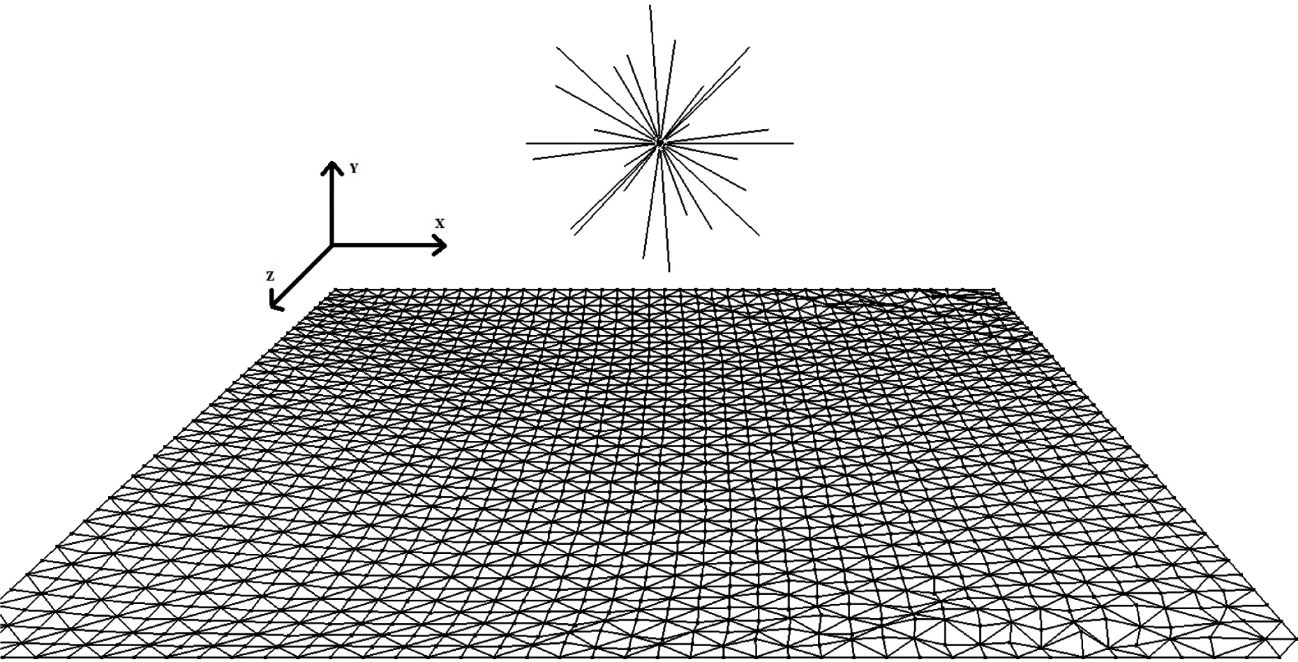
We consider a virtual skin composed by an array of particles connected by springs, as shown in Figure 1. The skin model is explored using a sphere controlled by a haptic device (Figure 2). It is assumed that the interaction between neighboring particles on the mesh follows Hooke’s force law in which the force is proportional to the displacement of the string.12 A simplified method to calculate the force exerted by the skin on the haptic sphere is proposed next.

Bidimensional particle array of the skin model.
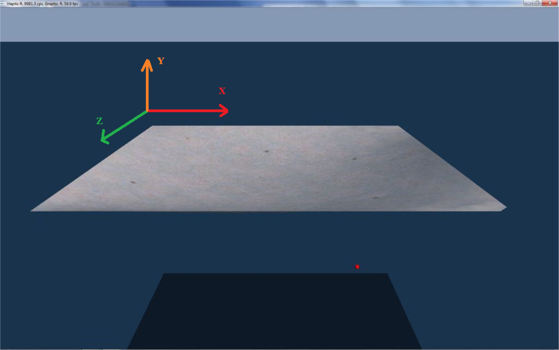
Deformable object to be explored by a haptic interaction point.
To calculate the position of the HIP-skin collision and the force exerted by the skin on the HIP in the virtual environment, an algorithm has been developed based on ray casting from the center of the HIP in different radial directions. The number of rays can be set between 26 and 98. We exploited NVIDIA PhysX to calculate the positions of all skin’s particles. It allows the possibility to calculate the distance between the haptic sphere and the skin at each instant. The number of rays, the HIP radius, the skin thickness, and the density of particles on the skin model can be adjusted in order to make the physical force felt by the user correspond to the visualization given by PhysX, as explained below.
An algorithm based on the penalty method was used to reduce calculation times for HR.12 According to this algorithm, there is a contact between the HIP and the skin surface when the distance between the HIP’s center and the skin mid-plane is lower than the HIP radius plus half the skin thickness. When a collision occurs, the number of rays intersecting the skin and the precise locations of the corresponding HIP-skin contact points are calculated. For each ray that is in contact with the skin, the initial contact point’s coordinates are recorded. As the HIP is pushed against the skin, a displacement vector is calculated from the initial and final ray contact-point’s coordinates. The displacement vectors corresponding to the different HIP-skin contact points are added, and a vector force is generated from them and sent to the haptic device, as presented below.
Consider the exploration of a virtual skin, which is an elastic deformable surface. As stated above, the skin is represented by NVIDIA PhysX as an array of connected particles through spring-damper-like interactions. It has physical properties such as width, length, thickness, and particle density, as well as stretching and tearing qualities.
The exploration is performed with a HIP, represented as a sphere with specific radius. A haptic device controls the HIP, which casts rays to detect collisions and rendering forces originated at the HIP’s center (Figure 3). For each ray that is casted, an estimation is made to determine whether there is a collision between the skin and the HIP. If there is a collision, the ray’s coordinate at the HIP’s radius is considered the first contact point, Pi1 (Figure 4(a)). It is important to mention here that for simplicity, Figure 4(a) is shown in two dimensions but calculation is done considering three dimensions. The coordinates are recorded to later calculate the corresponding displacement vectors. Given that NVIDIA PhysX determines the planes generated by adjacent particles on the mesh, it is always possible to find the distance between the HIP and the skin’s mid-plane along any ray. In this way, this distance can always be calculated regardless the rays’ fall directly on a vertex or on a particle of the mesh.
Skin model made of particles connected by springs and dampers and haptic sphere with rays.

Generation of displacement vectors. (a) Initial contact of the first point Pi 1. (b) Contacts of the following rays. (c) Displacements of the initial contact points. (d) Displacement vectors.
Perpendicular HIP displacement against the skin
As the HIP continues its movement against the skin, in the perpendicular direction, and this starts to warp, the distance to the closest point on the mesh is also calculated for each of the other rays intersecting the deformable surface. Applying the same criterion for the initial contact point, new initial contact points,
The positions of the actual contact points P1, P2, and P3 at a later time are shown in Figure 4(c). Therefore, their corresponding displacement vectors,

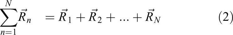
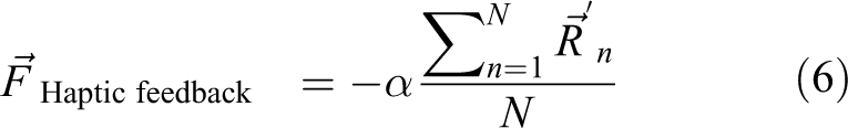
The sum of all displacement vectors for the N rays intersecting the skin is then calculated using the following equation
Therefore, the haptic feedback force is calculated as follows
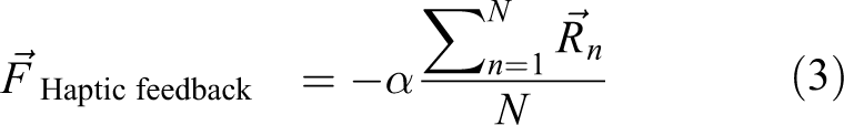
Equation 3 is based on Hooke’s law, which states that string forces are proportional to the particle displacement from its equilibrium position. Therefore, in this article, the average displacement of all particles in the mesh in contact with the HIP is taken into account, instead of taking the displacement of only one particle of the skin. In this equation, α is an empirical adjustment factor used to increase or to decrease the haptic response, and the minus sign is included to represent the direction of the force exerted by the skin on the haptic device. The value of α depends on the skin’s elasticity or strength, and it is chosen to match the physical effort felt by the user when moving the haptic device to the visual perception on the screen. The larger its value the larger the physical effort made. In this work, the value that best satisfied our requirements for a typical human skin was 0.2. To obtain this value, several tests were performed to recreate the best sensation. This is the algorithm used in this article for calculating feedback forces when the HIP pushes perpendicularly against the skin.
Tangential motion of the HIP on the skin
It is worth mentioning that if the position of the initial contact point is fixed in the previous calculations, undesirable and non-realistic forceful forces may be produced for large displacements. This problem arises and becomes particularly critical when the sphere is moved tangentially to the skin. To correct this situation and to improve the haptic perception when the HIP moves tangentially to the skin, a modification of the initial contact point coordinates is proposed, as follows

In this relation:
Pn: Actual contact point position.
k: “Maximum distance constant” used to limit the maximum force to be sent to the user. Its value is less than 1. In this work, it was found that the value that best reproduced the force perception when exploring tangentially the skin model with the HIP was 0.3. This value was obtained after a series of tests using the haptic device to perceive the best response.
In this calculation, the position of the new initial point is updated each time the HIP displacement exceeds a distance of 0.3 units (the virtual skin dimensions are 10 × 10 units, see below). This allows to properly reproduce a constant “kinetic friction-force” sensation when displacing the HIP in a tangential direction on the skin.
It is important to specify at this point that PhysX reproduces the appropriate visual behavior (motion) of the skin model (with similar properties to those of a human skin) in the animation, but does not provide the actual force values involved in it. In this work, a simple way of extracting feedback forces on the HIP is proposed; therefore, the empirical values for α and k parameters introduced previously are chosen to best match the visual animation with the tactile sensations felt by the user handling the haptic device.
The new calculation’s geometry can be seen in Figure 5. First, the initial contact for point 1, Pi1, is presented in Figure 5(a) (at time t0). In Figure 5(b), the next contact position for point 1, P1, and the initial contact positions for points 2 and 3, Pi2 and Pi3, at time t1 are shown. Finally, in Figure 5(c), the actual position of point 1 and the generation of the new displacement vector for point 1,

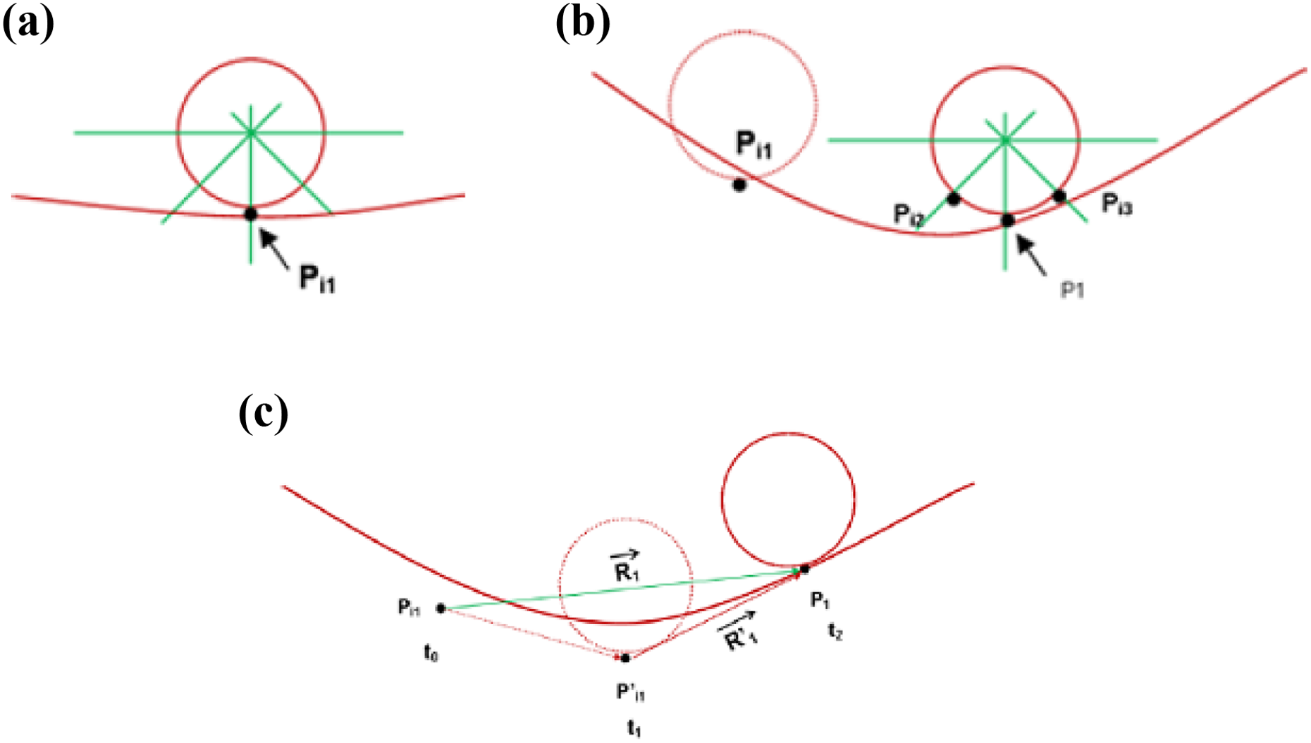
Displacement vectors for tangential displacements. (a) Initial contact position for point 1. (b) Tangential sliding and initial contact positions for points 2 and 3. (c) Sketching the new displacement vector for contact point 1.
Therefore, the new haptic force feedback is calculated by replacing
This is the algorithm used in this work to send the force feedback to the haptic device for tangential displacement of the HIP on the skin.
It is important noting here that: If the HIP is moved backwards, away from the skin, the skin model moves back to its original place. In this case, the force strength on the HIP is reduced according to the modulus of equation (6), and it becomes zero when there is no more contact between HIP and the skin. PhysX already reproduces proper cloth rupture visualization for large vertical downwards/upwards displacements of the HIP on the skin, according to skin width and flexibility properties from PhysX libraries. When this occurs, there is no more contact point between the skin and HIP, so the feedback force goes back immediately to zero (equation (3)).
Architecture
In this work, the simulator was build by taking as basis the architecture proposed by Salisbury et al.. 10 However, according to the components needed for a virtual environment of this type, an adaptation was made (Figure 6).

Architecture proposed. The architecture is composed of three blocks: ViR, HR, and simulation. ViR: visual rendering; HR: haptic rendering.
One of the objectives of this work is to demonstrate that using some engine libraries could reduce the time and effort to develop medical applications that combine the use of haptic devices with virtual environments. For example, using NVIDIA PhysX library facilitates the modeling of virtual skins by using its cloth models. However, the problems of handling collisions between flexible and rigid bodies for haptic interaction presented important challenges. This library does not provide the necessary values to calculate feedback forces. Therefore, a contribution in this architecture was to add a model of collision detections (which we call geometric), in order to properly couple the rest of the modules to the system.
It has to be noted that the architecture proposed by Salisbury et al. had to be developed and programmed to obtain a practical application.
The following paragraphs describe in detail each of the blocks of this architecture.
Simulation
A physical force-feedback human-computer interface (two haptic devices) coupled with a virtual simulation using NVIDIA PhysX 2.84 and OpenGL 2.2 enables the user to manipulate a virtual skin, which simulates the behavior of the human skin and a suture thread. This physics engine is able to manage collisions between objects and performs its calculations on the GPU. However, when collisions between solid and deformable objects occur, PhysX does not send this information to the developers environment to provide HR. To overcome this deficiency and generate an appropriate haptic response between the skin (represented as a cloth) and the HIP, a geometric module was developed using the simplified method described before.
Haptic rendering
For the purposes of this work, three blocks of HR were developed: (i) Collision detection and response are performed by the simplified method, (ii) response force between colliding solid objects used the “penalty method” standard technique, 10 and (3) the control algorithm block includes the restricted maximum force, and routines to improve the perception, according to the haptic device that is being employed. Finally, force feedback experienced during the simulation is provided to the user using the haptic devices.
Visual rendering (ViR)
In this section, the necessary operations to create the environment and display it on the video device are done. NVIDIA PhysX 2.84 and OpenGL 2.2 generate the virtual environment by using basic deployment techniques. PhysX is in charge to deploy the virtual skin, and OpenGL was used to create the deformable thread. Subroutines for collision handling were programmed to combine both visualizations and display the final scenario. Finally, it has to be noted that no hardware acceleration was used in SutureHap.
Implementation
The details of the deployment environment, as well as the component parts, will be described in the following subsections. The simulation was implemented on a Dell workstation with an Intel Xeon E5620, 2.4 GHz processor, 12 GB RAM, NVIDIA GeForce 9800 GX2, and running the Windows 7 64 operating system. A pair of phantom omni haptic devices was used to interact with the virtual skin and thread models. We built an intermediate “sample and hold” routine to compensate different refresh rates, because NVIDIA PhysX responds to frequencies up to 60 Hz while the haptic device needs to be updated at a rate of at least 1 kHz. Therefore, during the time period, it takes to PhysX to change its information (1/60 s), the input values sent to the haptic device are repeated 16 times, and they are updated until the beginning of the next period. In the following sections, the processes that are performed in SutureHap’s architecture are described. Figure 7 depicts the corresponding flow diagram.
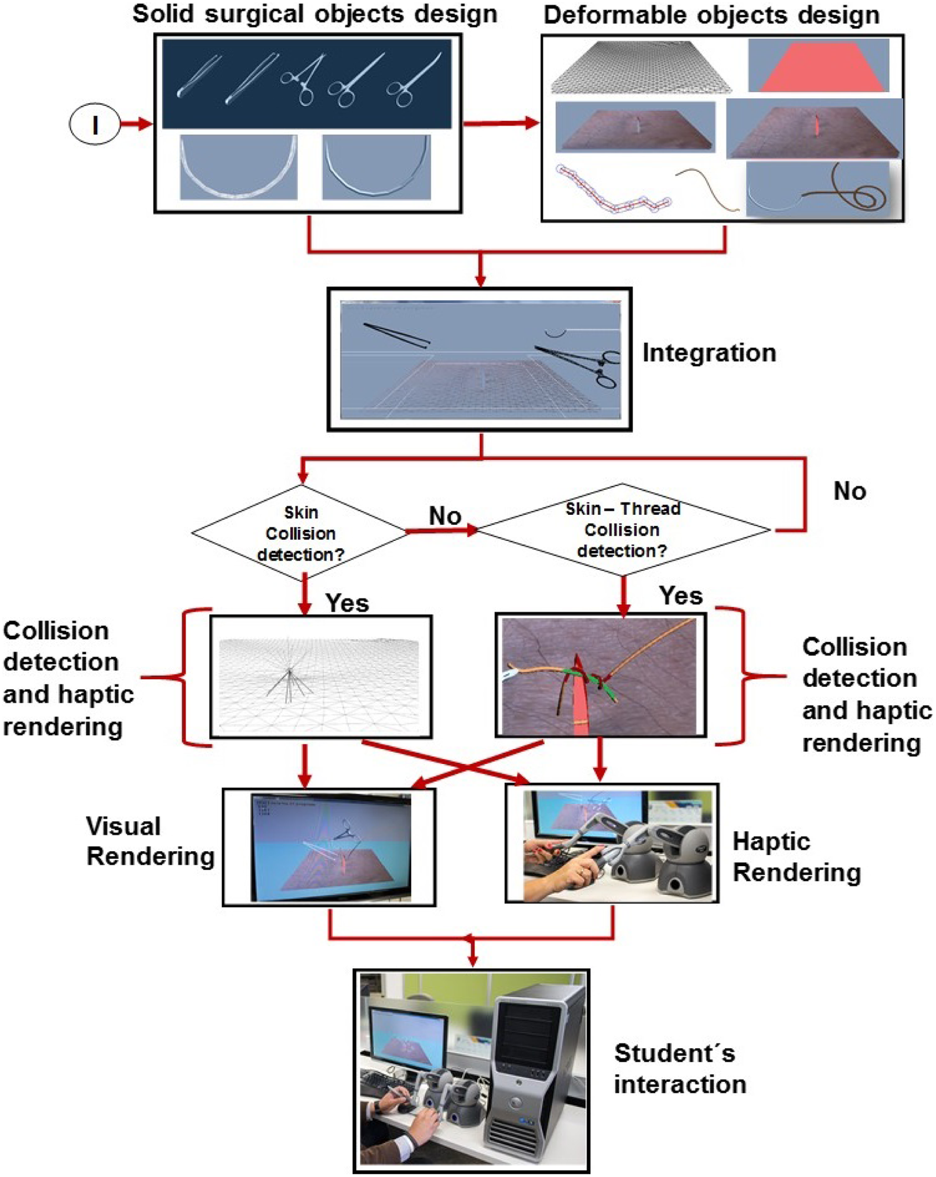
Flow diagram of SutureHap architecture.
Surgical tools
In this research, it was necessary to prepare several models of surgical tools. The models were created using Autodesk Maya (Figure 8). For the initial stage of this research, only the blunt-nosed thumb forceps, Kelly forceps (needle holder), and Metzenbaum surgical straight scissor were used.

Various models of instruments developed to be used in SutureHap. From left to right: Kelly forceps and blunt-nosed thumb forceps.
Moreover, a curved needle model was created to perform the suturing task on the virtual environment (Figure 9). This needle is attached to the suture thread, which is created at the time of execution without a predefined pattern because it possess a dynamic behavior.

Model of the suture curved needle used in SutureHap.
Finally, in order to simulate movements in SutureHap, each tweezer model has been segmented in separated parts, with the pivot in the right place for the rotation of each piece. In the environment, the user can rotate them as he desires, and he can interact in the virtual environment by opening or closing the gripper of each tool.
Physical and geometric simulation
The algorithm presented in the previous section was implemented in a NVIDIA PhysX environment. An initial skin model of 10 ×10 units containing 3362 triangles and 1764 vertices was implemented. This corresponded to a distance of 0.25 units between adjacent vertices. The HIP sphere had a radius between 0.05 and 0.1 units. The skin thickness ranged between 0.2 and 0.8 units. Several tests of the skin model response, while interacting with the HIP sphere, were performed as explained later. Although PhysX allows working with arbitrary distance units, in this article, it was assumed that 1 unit in the simulation equals 1 cm, in order to transform arbitrary units to physical ones. Therefore, the skin dimensions are 10 × 10 cm2.
Within the NVIDIA PhysX environment, the skin was generated using the NxCloth class, while for the HIP, a kinematic actor of the NxActor class was used. A special routine was developed to generate and control the rays used to detect skin-sphere collisions and calculate the force feedback vectors. When a ray intersects the skin, the distances to the closest point and closest vertex are calculated, and the simplified method described previously is performed to detect whether a collision occurs.
Figure 10 shows the HIP ray casting above the skin. In the figure, thin rays are not yet in contact with the skin while thick rays are already colliding with it. Figure 7(a) shows only one ray in contact, while Figure 7(b) shows seven rays in contact. Force feedback is determined from the vectors created from these contacts. In addition to performing an accurate physical simulation of the skin, NVIDIA PhysX is also able to simulate perforations or even ruptures on the skin. In these cases, the HIP is held in the correct position on the surface of the skin at all times. If the HIP pierces the skin, the algorithm to simulate the behavior and force strength sends the appropriate force feedback in the correct direction to the haptic device. It is also possible to simulate tearing in the skin when the HIP is interacting with it. Finally, the environment was used to perform a simple suturing task. We called this application SutureHap. Tools were mounted on two HIPs and a thread model was added to enable users to perform a basic suturing task. A preliminary version of SutureHap is described in the study by Ricardez et al. 23

HIP is ray casting to detect a collision with a virtual skin. (a) One ray in contact with skin. (b) Seven rays are in contact with the skin’s surface. HIP: haptic interaction point.
Skin model
As it has been mentioned before, a deformable mesh, based on the representation of cloth model, was used to render the skin. This mesh is placed in the center of the skin, and it is configured with a certain width or thickness, which improves skin characteristics. To achieve different consistencies, the elasticity and damping parameters are adjusted. To generate the skin, PhysX Nx-Cloth class is used. In the case of the haptic avatar, a kinematic actor from PhysX NxActor class is created. Finally, to improve the appearance, a similar texture of human skin is added (Figure 11).

SutureHap applies a texture to virtual skin to simulate similar visual features on the environment as the ones seen on a real suture task.
Thread model
To create a proper thread model, this work used as basis the technique developed by Lian and Chen 24 combined with the ones proposed by Brown, Latombe and Montgomery. 25 This methodology was implemented to achieve proper interaction in the GPU between the simulated skin and the thread, which should have a strict control of collision detection. Since PhysX engine was used in this research, an additional mechanism of collision detection was added. To build the movement of the thread, the FTL algorithm was used. 25 Figure 12 shows a segment of the thread. In this model, particles are represented by spheres. The line segments connecting the center of each particle can be appreciated and the cylinders generated from the particles are observed between the thread and other objects; a method, based on geometric properties of line segments, is formed by joining the centers of the particle.

Thread segment made from particles, represented as spheres
When segments are too close and it is not possible to move them to avoid a collision, the proposed algorithm consider that a knot can exist if and only if the following conditions are met: 10 or more colliding cylinders must exist. Colliding cylinders are in at least two blocks and each block is contiguous. Each block contains at least four contiguous cylinders.
The above conditions are met in the example of Figure 13, where two segments of the thread, one green, and one red are shown. Cylinders ABCDEF, which are contiguous and belong to the red segment, are colliding against cylinders abcde, which are also contiguous and belong to the green segment.

Knot tying detection example.
It is important to highlight that in order to detect colliding segments that belong to different blocks, there must be a distance interval of at least five cylinders between the segments. When a possible existence of a knot is detected, the distance of these segments with respect to the skin (cloth) is evaluated. If the knot comes to a predetermined distance, it is considered that the knot is getting closer and it will be fixed. Consequently, the system will immobilize all segments that form the knot.
Evaluation and results
In this section, different tests to assess the collision algorithm are presented first. Later, a user-oriented test was conducted to validate SutureHap as a learning tool to practice basic suturing skills.
Collision algorithm
The simplified collision algorithm presented above was tested. Perforation and sliding tests were carried out (Figure 14). For this purpose, the calculated feedback force that corresponds to different interactions between the HIP and the skin was explored, taking into account the following parameters: number of cast rays by the HIP, haptic sphere size, skin width, effect of gravity, effect of HIP’s direction of motion, and particle density of the mesh. In the following tests, the force is given in Newton (N), which corresponds to the units provided by the haptic device. On the other hand, displacements are given in distance units (1 unit = 1 cm).

Different tests performed: (a) Perforation test and (b) sliding test.
Number of cast rays
The number of HIP rays can be varied between 26 and 98 (i.e. 45 and 22.5 degrees of separation between adjacent rays, respectively). We wanted to study whether increasing this number might produce a smoother and more precise perception of the feedback force, because having more intersection points between the HIP and the skin implies including more displacement vectors in the average feedback force calculation (equation (6)). Perception tests show that there are no significant differences for different numbers of rays, so it was decided to carry out calculations with 26 rays in order to reduce processing time.
Haptic sphere size
The effect of the skin thickness was tested performing displacements of the HIP perpendicular to the skin without gravity (Figure 15). In these tests the skin thickness was 0.4 units. The HIP is moved upwards, along the Y-axis, pushing the skin from below. Two different values of the HIP radius were considered: 0.05 (Figure 15(a)) and 0.1 units (Figure 15(b)). In the figures, the force value is plotted against the skin displacement from its initial position. Note that the force value is negative because it represents the force of the skin on the HIP. It can be seen that for both HIP’s radii the force response is approximately proportional to the displacement, which in fact corresponds to the resistance that a skin would exert against an exploring sphere in a real environment. It can also be appreciated that the force strength is largest for the biggest HIP radius, as expected in a real setup. Additionally, it is observed that the force value goes back to zero when the skin is pierced.

Effect of HIP diameter on force feedback without gravity. HIP: haptic interaction point.
Skin width
The effect of the skin thickness was tested performing displacements of the HIP perpendicular to the skin without and with gravity (Figures 16 and 17, respectively). The radius of the HIP was set at 0.05 units and two different values of the width of the skin were 0.2 and 0.8 units. It is clearly seen in these figures that the force strength is much greater for the thicker fabric, which is consistent with what it is expected in the real world.

Effect of the thickness of skin in the force feedback without gravity.

Effect of skin thickness on force feedback with gravity.
Effect of gravity
PhysX allows incorporating the gravity effect in the skin visualization. A standard value of 9.8 m/s2 is assumed. In Figures 16 and 17, the feedback force is plotted against HIP displacement without and with gravity, respectively. It can be seen that the behavior of the system is similar in both cases. It can be appreciated in the figures that the initial contact with the skin was at Y = − 0.1 cm without gravity and at Y = − 1.0 cm with gravity, because the skin hangs with gravity, as expected. Additionally, it is observed that the elongation for rupture point was similar in both cases.
Effect of the HIP’s direction of motion
Perforation and sliding tests were carried out(Figure 14). The skin was pierced from bottom to top or top to bottom (HIP moving along the Y axis). The corresponding force behavior has already been shown in Figures 15, 16, and 17, where the force quickly decreases to zero when the skin is pierced. In these figures it is also apparent that the rupture point force is larger for thicker skins and for greater HIP sizes, as expected.
Additionally, a sliding test, where the HIP was moved under the skin along the X or Z-axis, was made. The responses obtained are shown in Figure 18(a) and (b), respectively. This test was performed with no gravity, with a HIP radius of 0.05 units and a “k” factor equal to 0.3 (equation (4)). As mentioned before, this factor defines the maximum force to be sent to the haptic device. The system behavior was similar for both directions. It was also observed in this test that changing the diameter of the sphere or the thickness of the skin produced similar force plots.

Sliding test along the axes X and Z.
Particle density effect
Tests were made decreasing the distance between the particles of the skin from 0.25 to 0.1 units, which produces an increase of the number of particles from 1764 to 10404. We obtained better stability (smoothness) of the response of the haptic device for the case of 0.1 units (higher particle density), as shown in Figure 19. This effect is perceived for perpendicular as well as tangential displacements of the HIP. For perpendicular motion, response is clearly smoother for larger particle densities, as it can be seen when comparing Figure 15(a) (1764 particles) with Figure 19(a) (10404 particles). All other data were identical: no gravity, HIP radius = 0.05 units and skin width = 0.4 units. The same conclusion is reached for perpendicular motion, comparing the force response of Figure 18(a) (1764 particles) with that of Figure 19(b) (10404 particles). All other parameters are the same as in the previous comparison. However, it was observed in the tests that if the separation distance is smaller than 0.1 units, the NVIDIA PhysX performance decreased because of excessive calculations.

Tests with high particle density: (a) piercing from bottom to top and (b) sliding along the longitudinal X-axis.
Finally, to evaluate user perception based on the force feedback behavior perceived during the simulation, a test was carried out with 15 volunteers of different ages. Participants were graduated students of physics, mathematics and computer science programs, who had no previous experience with haptic devices. Each user was placed in front of the computer to test the simulation. A brief introduction on the use of haptic devices was given (Figure 20). Each test had a maximum duration of 10 min. The simulation starts by asking the user whether he is right-handed or left-handed. Even though the simulator supports two haptic devices, only one of them was used, which corresponds to the one that the user selected.
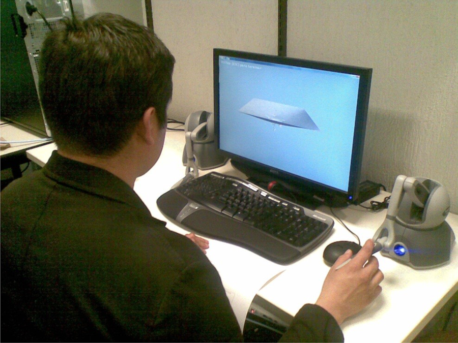
User performing the haptic perception test of the skin on the simulation, implemented on a NVIDIA PhysX cloth model.
They were instructed to perform the following operations with the environment: piercing the skin model from top to bottom piercing the skin model from bottom to top sliding the HIP along the x-axis over and under the skin model sliding the HIP along the x-axis under the skin model sliding the HIP along the z-axis over the skin model sliding the HIP along the z-axis under the skin model
For the experiment, the HIP had a radius of 0.05, the skin model thickness was set at 0.4, the distance between skin’s particles was 0.1 and with a radius of 0.3. Finally, during the simulation, gravity was enabled.
At the end of the experiment, each user answered a 3-point Likert-type scale perception questionnaire (agree, indifferent, or disagree). In this questionnaire, they expressed how they experienced the simulation. Additionally, a “yes/no” question was added to let participants indicate whether the haptic response is close to a real task.
The results obtained are shown in Figure 21. It can be observed that 93.33% of the participants agreed with the experienced sensation when they pierced the skin from bottom to top. 86.66% agreed that the perceived sensation when piercing from top to bottom was realistic. The same percentage was obtained on the task of sliding the HIP over and under the skin along the x-axis and sliding the HIP under the skin along the z-axis. Finally, 73.33% of the participants agreed that the sensation felt by sliding the HIP over the skin along the z-axis was real.

User perception of the haptic feedback perceived during sliding the HIP in different directions of the skin, modeled using the NVIDIA PhysX cloth model. HIP: haptic interaction point
Lastly, 100% of participants agreed that the feeling is close to a real task on the “yes/no” question. Therefore, it indicates that from the sample of participants that used the simulator, the proposed method can be used to generate adequate force feedback, mainly to perform perforations from bottom to top of skin models.
Suturing task
Two testing processes were conducted with: (a) 12 volunteers from different areas and (b) 4 senior medical students who had previous knowledge in the area of suturing (Figure 22). All participants were from Tecnologico de Monterrey, Mexico City Campus. The objective of these tests was to evaluate how users appreciate the behavior of SutureHap simulator. The aspects to be evaluated in the tests were the visualization, modeling, and haptic response of the system. A brief introduction about the use of haptic devices was given, and two videos were shown in each test. The first video showed how a surgeon performs a simple suture point in a pigskin. On the other hand, the second video showed the suture procedure applied in the simulator by an expert. Each user worked with SutureHap for approximately one hour. Participants were instructed to become familiar with application, and when they felt ready, they proceeded to perform a suturing task. Finally, an online perception questionnaire on their experience with the system was applied once they finished their practices.

User performing a simple suturing task in SutureHap.
As shown in Figure 23, 81.25% of the participants felt that the skin is represented correctly, and 87.5% of the participants considered that the tweezers and needle were correctly represented, but only 62.5% of the participants felt that the thread is properly represented. 81.25% considered that the force feedback is consistent with the graphical environment, and 100% of the participants agreed that the distribution of the elements is appropriate. As shown in Figure 24, 93.75% of the participants agreed that the use of elements in the environment itself is intuitive. However, 75% considered that it was necessary to improve some aspects to make a suture in the virtual environment, such as the perception of depth and flexibility of the thread. Finally, 87.5% of the participants stated that they will recommend the environment to other people to complement their training process, as shown in Figure 25.
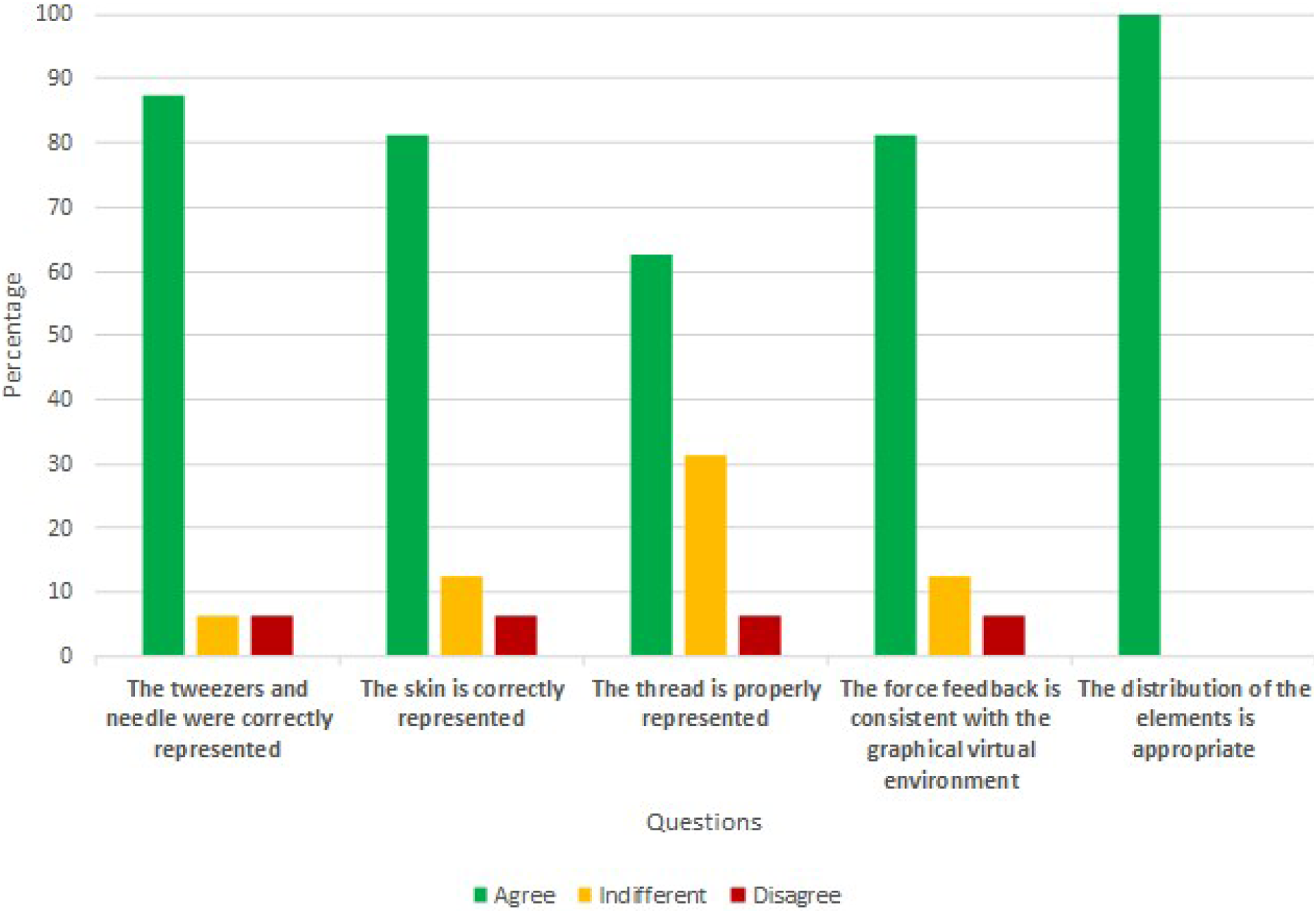
User perception results obtained from the questionnaires.
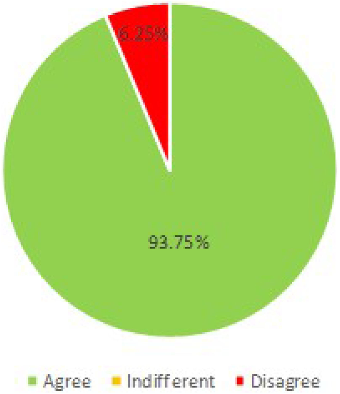
User perception results obtained from their experience with SutureHap virtual environment.

Results obtained from the questionnaires where participants specified if they would recommend SutureHap virtual environment for training purposes.
In general, results obtained from these evaluations state they agreed that the visual representation of objects in SutureHap was adequate (thread, needle and tweezers), that the feedback force they felt when interacting with the skin was consistent with that expected in a real suture operation, and that the use of SutureHap was reasonably adequate.
On the other hand, they suggested some improvements to the system. The most important were to design an easier manipulation of tweezers for holding objects, for applying torsional forces and making knots, a better perception of the depth dimension, and a faster system response. Nevertheless, they mentioned that it is very important to develop this kind of haptic simulators because they provide the opportunity of practicing as may times as desired in a safe environment. They also pointed out that SutureHap is very promising and could be very useful to develop surgical skills, and they stated that they would recommend it for medical purposes.
Conclusions
The NVIDIA PhysX engine was used to produce a fast and effortless process in the creation of a virtual training environment for suturing tasks. It offers libraries that let developers implement appropriate deformable bodies (e.g. for skins), it accelerates the environment response, and it exploits computers’ GPU potential. However, PhysX does not detect collisions between deformable objects, which makes haptic feedback calculation arduous. Additionally, although NVIDIA PhysX detects and simulates collisions between rigid and deformable bodies, it does not provide physical information to the user, which makes the calculations for haptic feedback difficult.
A simplified method is proposed to obtain the force feedback exerted by a deformable surface, a virtual skin, on a haptic device. The suggested algorithm allows a fast and simple feedback force calculation from the displacements of those skin particles that are in contact with the HIP when it is pushed against the skin. The HIP-skin collision is determined from the positions of intersection points between a series of rays that are casted from the sphere to the skin surface. In the testing phase, perforation and sliding tests were carried. For this purpose, the calculated feedback force that corresponds to different interactions between the HIP and the skin was explored, taking into account the following parameters: number of cast rays by the HIP, haptic sphere size, skin width, effect of gravity, effect of HIPs direction of motion, and particle density of the mesh. Additionally, it was observed that the response force exerted by the skin on the haptic device, calculated according to the proposed method, has the following characteristics: (i) incrementing the size of the HIP increase the force feedback generated when it is pushed perpendicularly against the skin; therefore, the limit breaking force is also increased; (ii) increasing the skin thickness also produces a rise in the force feedback; (iii) the physical behavior of the force feedback is similar with or without gravity, and the rupture limit is similar in both cases, the only difference is the position of the initial contact point; (iv) sliding the HIP below the skin surface along the x (longitudinal) or z (depth) axes generates similar results.
Based on our experience in developing other applications, we found that the use of PhysX reduced the development time and modeling effort of Suturehap by 30%. This percentage could be further minimized in future applications because the problem of detection of collisions between flexible and rigid bodies has been solved.
An architecture to facilitate the integration of haptic devices was designed. The study case proposed in this work was the development of an application to perform a suturing task, SutureHap. Some tools were mounted on two HIPs and a thread model was added to enable the users perform a suturing task. As PhysX engine does not detect collisions between deformable objects, an additional mechanism of collision detection was added. It was also necessary to prepare several models of surgical tools. The models were created using Autodesk Maya. For the initial stage of this research, only the blunt-nosed thumb forceps, Kelly forceps (needle holder), and Metzenbaum surgical straight scissor were used.
Even though current researchers use similar frameworks or approaches, we identified that they did not take into consideration the way suturing tasks are performed in medical schools. For instance, in the research made by Choi et al., they presented a linear needle to perform the suturing task, but these procedures are performed by using a curved needle, which facilitates the insertion and handling of tools. Therefore, by implementing this type of needle in SutureHap, surgeons can perform the task according to the standards they know. On the other hand, in the work of De Paolis, the system uses two Falcon Novint haptic devices, which provide only three degrees of freedom. However, suturing tasks require the use of torsion. Therefore, by using 6 degrees of freedom haptic devices in SutureHap, two geomagic touch, the creation of knots and union can be performed properly.
Finally, the system was tested by volunteers from different areas and senior medical students. The system showed a stabilized performance and it responded smoothly during tests. The interaction between the thread, generated by geometrical methods, and the skin, created using physical methods, worked correctly. All these findings support our hypothesis that haptic devices simulators can reproduce the expected behavior of real systems. Therefore, we can conclude that the incorporation of haptic devices in virtual environments greatly increases the ability of users to promote meaningful learning. We are currently working on designing better graphics visualizations to enhance depth perception of the environment, and we are improving the tools manipulation and response routines to provide users an easier navigation in the environment. Finally, as a future work, an intelligent assistant will be developed to allow users to receive automatic feedback from the system, according to their performance in suturing tasks.
Footnotes
Declaration of conflicting interests
The author(s) declared no potential conflicts of interest with respect to the research, authorship, and/or publication of this article.
Funding
The author(s) received no financial support for the research, authorship, and/or publication of this article.