
Abstract
We present a handrail detection and pose estimation algorithm for the free-flying Astrobee robots that will operate inside the International Space Station. The Astrobee will be equipped with a single time-of-flight depth sensor and a compliant perching arm to grab the International Space Station handrails. Autonomous perching enables a free-flying robot to minimize power consumption by holding its position without using propulsion. Astrobee is a small robot with many competing demands on its computing, power, and volume resources. Therefore, for perching, we were limited to using a single compact sensor and a lightweight detection algorithm. Moreover, the handrails on the International Space Station are surrounded by various instruments and cables, and the lighting conditions change significantly depending on the light sources, time, and robot location. The proposed algorithm uses a time-of-flight depth sensor for handrail perception under varying lighting conditions and utilizes the geometric characteristics of the handrails for robust detection and pose estimation. We demonstrate the robustness and accuracy of the algorithm in various environment scenarios.
Introduction
The NASA Astrobee Project is developing the next-generation free-flying robots that will operate inside the International Space Station (ISS) alongside the astronauts. 1 Astrobee’s primary objective is to provide a zero-g research facility for guest scientists. The Astrobees will replace the SPHERES robots that have been among the most-used facilities on the ISS since they arrived in 2006, hosting experiments on topics ranging from magnetic propulsion, 2 to simulated satellite inspection, 3 to studying the dynamics of tethers in zero-g. 4
Astrobee will carry on the SPHERES tradition, while opening up new areas of research with its greatly expanded capabilities, which include improved autonomy, better support for guest science hardware add-ons, a built-in suite of cameras, and a robot arm. If you have new ideas about how to use zero-g robots, the Astrobee Research Facility (https://www.nasa.gov/astrobee) is currently seeking guest scientists to begin experiments on the ISS in late 2018. Experiments already under development for Astrobee include an Radio-Frequency Identification (RFID) reader for tracking equipment on ISS, a new gripper using a gecko-inspired adhesive that could enable perching on flat surfaces, and an investigation using an arm for acrobatic maneuvers that could reduce fuel usage for future extra-vehicular free-flyers.
In addition to supporting guest science, the Astrobees can be teleoperated as free-flying cameras to improve situation awareness for flight controllers. They can also perform surveys with a variety of environment sensors, for example, monitoring CO2 concentration, radiation, and noise levels. By using robots to sample rather than astronauts, more data can be collected more often with less crew time. Better information will inform future improvements to the life support systems the astronauts depend on.
The Astrobees have a variety of pose estimation modes that rely on different sensors as shown in Figure 1 and serve different operational needs as shown in Table 1. The core pose estimator is implemented as an extended Kalman filter (EKF) that can accept different inputs. 5 This article focuses on the perching mode.

Astrobee robot geometry.
Astrobee pose estimation modes.

ISS: International Space Station; IMU: Inertial Measurement Unit; DOF: Degree Of Freedom.
There are various types of handrails on the ISS as shown in Figure 2 and the Astrobee will be equipped with a handrail perching system, which consists of a time-of-flight (ToF) depth sensor and a compliant perching arm, to hold its position for minimizing power consumption, recording videos, and monitoring the ISS interior. Since Astrobee is a small robot with many competing demands on its computing, power, and volume resources, we limited ourselves to using a single compact sensor and a robust, lightweight detection algorithm for perching.

The lighting condition inside the US Destiny laboratory during waking and sleep periods.
In general, perching is an important ability for flying robots, such as unmanned aerial vehicles (UAVs) and micro aerial vehicles (MAVs), to minimize power consumption while performing stationary tasks in a fixed location such as video streaming and telecommunication relay as shown in Figure 3. For real-time perching, a fast handrail detection algorithm is required to robustly detect the handrail and estimate its relative pose to the robot.

Artist’s concept of the Astrobee robot taking video of an astronaut activity while perching.
We propose a robust handrail detection and pose estimation algorithm on the ISS. All the handrails on the ISS have the same thickness and are made of similar material, but they vary as to length, mounting geometry, and background wall texture. There are major similarities between the handrails on the ISS and the other handrails in our daily lives such as handles in doors, refrigerators, and cabinets: they are cylindrical and attached to flat surfaces. Thus, the proposed algorithm can also be applied to various tasks for autonomous robots to perch or manipulate handrails. In fact, detecting the handrails on the ISS is quite challenging due to the cluttered environmental condition of the ISS with varying lighting conditions. To simplify our algorithm and particularly our testing approach, we focus on the 70% of handrails that are “typical,” that is, length > 50 cm and mounted in the middle of a wall. Most of the remaining handrails are less suitable for perching in any case, because they are found near narrow hatchways where Astrobee would be more likely to obstruct astronaut motion. The task of the handrail estimation is to confirm that a target handrail exists and provide a relative pose estimate between handrail and gripper that is sufficiently accurate (3 cm) and stable to enable robust grasping. After successful perching, the arm joints act as a pan/tilt base to point cameras fixed on the robot body; to provide the maximum range of motion, the desired perched geometry has the arm link normal to the plane of the wall.
The handrail estimator complements the general-purpose visual pose estimator that provides less accuracy but works anywhere in the ISS US segment. 5 The perching process works as follows: The user views a 3-D model of the ISS with known handrail locations marked and selects a handrail to perch on. Astrobee then moves to a target pose near the handrail using its general-purpose estimator. Once at the target pose, the handrail should be in the ToF sensor field of view and in the vertical orientation that is compatible with the gripper. The robot then switches from general-purpose navigation to visual servoing on the handrail to complete the perching approach.
The task of handrail detection and pose estimation is an instance of the general problem of recognizing 3-D objects and estimating their poses. 6,7 There have been numerous methods for 3-D object recognition such as 3-D keypoint detection. 8 –10 However, most of them focus on identifying multiple objects using RGB-D sensors. 11 –13 Since our goal is to detect a handrail and estimate its pose with a computationally limited processor and a single depth sensor, the previous 3-D object recognition approaches with the RGB-D sensors are not suitable for this problem. The Robonaut 2 at the NASA Johnson Space Center has been developing a mobile system and the end effectors of the legs have a sensor package for handrail detection. 14,15 However, the system uses both a camera and a ToF sensor for handrail detection.
The handrail detection problem also has similarity with the handrail perception problem for autonomous door and drawer opening. 16 –18 However, most work in handle detection assumes that the handle is small enough to be shown its whole shape within the view area of sensors and the door does not have other attached objects on its surface except for the handle. Unlike the doors and cabinets where only handles are attached, the walls in the ISS have considerable numbers of cables and instruments attached along with handrails. Moreover, due to the length of the handrails and the limited field of view of the sensor, only part of the handrail is within the viewing field of the sensor as the robot approaches to the handrail for perching.
Unlike the other approaches that use both an RGB camera and a depth sensor, this article focuses on the approach with a single depth sensor for detecting the handrails in a cluttered environment with varying lighting conditions. We are using the CamBoard Pico Flexx sensor (PMD Technologies), which is much smaller (68 mm × 17 mm × 7.25 mm) than other off-the-shelf RGB-D sensors with similar range and resolution (224 × 171 pixel) that were available at the time the sensor was selected. For robust handrail detection and pose estimation, we utilize the geometric relationship between the handrails and the walls on the ISS as well as the geometric characteristics of the handrails. The proposed approach can be applied to handle and knob detection for autonomous door and drawer opening. It can be also used in various micro UAVs to perform a wide variety of tasks that require real-time autonomous navigation and aerial gripping with lower computational and energy requirements. 19 –21
Perching arm
As a part of the Astrobee robotic system, a compliant, detachable perching arm is being developed to support long duration tasks. This arm will grab ISS handrails to hold its position without using propulsion or navigation to minimize power consumption.
The prototype of the Astrobee perching arm in Figure 4 is developed to verify the grasping functionality and the range of pan-tilt motion. 22 The arm consists of two Dynamixel AX-12A motors and the tendons in the gripper are connected to a Pololu metal gearmotor (Pololu Robotics and Electronics). Dynamixel motors are directly controlled from a BeagleBone board and the Pololu motor is controlled using a Baby Orangutan B-328 board, where the desired commands are sent from the BeagleBone board via serial. The length and mass of the Astrobee perching arm are 24 cm and 315 g, respectively.

The Astrobee perching arm preliminary design (stowed configuration).
Handrail estimation
We consider handrails that are attached on the plane since all the handrails on the ISS must be attached on the wall and most of the handrails in general are also installed on the flat surfaces, such as door knob and refrigerator handle. Moreover, estimating the plane that the handrail is attached is essential for the robot to estimate its relative orientation to the handrail for perching. After the plane estimation, the algorithm filters out false-positive handrail points by using the geometric constraints between the plane and the handrail as well as the geometric characteristics of the handrail, such as the gap distance between the plane and the handrail as well as the width of the handrail. After the outlier rejection, the algorithm estimates a line from the filtered point cloud and clusters the line to determine the handrail that contains the most suitable handrail points.
The overall procedure of the proposed algorithm can be summarized as follows:
Plane estimation: From a point cloud (Figure 5(a)), estimate a wall (plane; Figure 5(b)).
Handrail outlier filtering: Filter out false-positive handrail points.
Gap distance test: Ignore points that are too close to the wall to be part of a handrail (Figure 5(c)).
Cross point test: Ignore points whose local neighborhood points do not satisfy the handrail geometry (Figure 5(d)).
Side width test: Ignore points whose local neighborhood points do not satisfy the handrail width (Figure 5(e)).
Line estimation and clustering: Estimate handrail candidate sets from the rest of the points and cluster them (Figure 5(f)).
Handrail selection: Determine the line set that contains the most suitable handrail points for grasping.

The handrail detection process. (a) A measured point cloud from the depth sensor. (b) The plane inliers of the estimated plane. (c) The remaining points from the plane outliers after gap distance test. (d) The remaining points after the cross point test. (e) The remaining points after the side width test. (f) The remaining points after line estimation and clustering.
Plane estimation and gap distance test
The handrail consists of one beam and two legs as shown in Figure 6(b) so that the handrail can be modeled as a combination of a long cylinder for a handrail beam and two short cylinders for two legs that connect the beam to the wall as shown in Figure 6(a). In this cylinder model, the diameter and the height of the handrail beam, bD and bH, are, respectively, set to 3.5 and 55.0 cm (or 105.5 cm for a longer handrail), and the handrail leg diameter, lD, and height, lH, are set to 3.5 and 6.5 cm, respectively. To utilize the geometric characteristics of the handrail on the wall, the proposed algorithm first estimates the plane coefficients and classifies plane inlier set, CPlane from a point cloud using Random sample consensus (RANSAC).
23
Since the gap between the plane and the handrail is fixed and the points measured from the handrail are within the plane outliers, the distance between the plane and the handrail points must be between lH and 
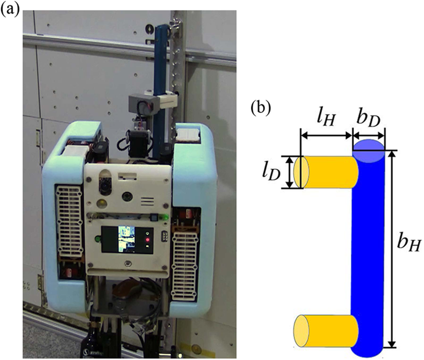
(a) Astrobee prototype perching on a handrail. (b) The handrail is modeled as a combination of one long cylinder (handrail beam) and two short cylinders (handrail legs).
where
Cross point test
The handrail beam is projected as a thick line in a 2-D depth image. In the cross point test, four cross points are defined for each testing point in the 2-D depth image and tested whether they satisfy the geometric relationship between the handrail and the wall. Figure 7 shows the four cross points of the testing point in the 2-D depth image where

The illustration of the cross point test on the 2-D depth image. The top-left and top-right figures show that the x-axis cross points,
The displacement vectors,

where

where αx, αy, and αz are the plane coefficients in
The set of points that pass the cross point test, CCross, is then defined as

where
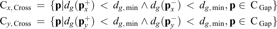
where dg, min is the threshold gap distance,
Side width test
There are various types of cables scattered around the handrails on the ISS as shown in Figure 2. Since the cables have similar shape to the handrails, some portion of the points on the cables could pass both the gap distance test and the cross point test, which could be considered as the false-positive handrail points. Since the thickness or width of the cables are different from that of the handrail, the side width test evaluates whether the width of the local neighborhood of the testing point is within the range of the handrail width.
In order to filter out the points from the cables, the x- and y-axes direction side width tests are applied to the points in Cx, Cross and Cy, Cross, respectively. Figure 8 shows the process of the side width test in a 2-D depth image. In the case of the x-axis direction side width test, the two edge points of


The illustration of the side width test on the 2-D depth image. (a) The two edge points,
where

where
Line estimation
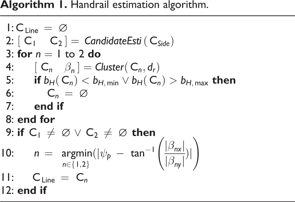
The handrail is further modeled as a line such that the line estimation process estimates the group of points that are within a threshold distance of the estimated line model. If there is a single handrail within a depth sensor view area, a basic RANSAC algorithm can be applied to estimate a line regardless of its angle with respect to the angle of the gripper. In the case of multiple handrails in the view area, the RANSAC algorithm simply selects one line model that has more inlier points than other line models. However, for the purpose of handrail grasping, the line model that has smaller angle with the handrail gripper must be selected as the line model of the target handrail. As shown in Figure 2, the handrails are either parallel or perpendicular to each other. The proposed line estimation algorithm utilizes this geometric relationship between the handrails by estimating the two most salient set of points that are perpendicular to each other and selecting the one that has smaller angle difference between its line vector and the gripper angle of the perching arm.
Algorithm 1 describes the overall handrail estimation process where CandidateEsti (CSide) is the handrail candidate estimation algorithm (algorithm 2) which returns two sets, C1 and C2, of the estimated lines that are perpendicular to each other. The clustering function in line 4, denoted as
Handrail estimation algorithm.
Algorithm 2 shows the handrail candidate estimation process that estimates two perpendicular line models and returns the two inlier sets of the line models. The algorithm first samples two random points from CSide and generates a sample line vector, β′. The inliers that lie on the line with a point
Handrail candidates estimation algorithm.

Localization
The overview of the EKF-based localization for Astrobee using a single camera was described by Coltin et al. 5 In order to maintain the same EKF localization process for the depth sensor observations, a collection of depth sensor features from the handrail and the wall behind the handrail is used. The difference of the measurement models between the sparse map landmarks and the depth sensor observations is that the residuals of the sparse map landmarks are fixed to two dimensions, while the dimensions of the residuals from the depth sensor observations change depending on the state of the handrail.
Handrail pose estimation
The origin of the handrail frame in the camera frame,

where
Measurement model
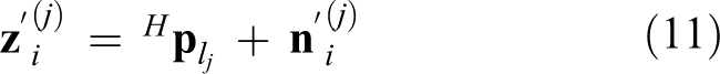
The measurement of feature j in the i th camera frame,

where

where the feature positions in the global frame and the handrail frame,

In the case where either of the end points of the handrail is detected, the residual of feature j in the i th camera frame,

where

are Jacobians of δθi and
As the robot approaches close to the handrail, none of the handrail end points would leave the field of view of the sensor so that the relative position of the robot along the handrail line vector,
The linearized residual for the new measurement is then calculated as

where

By multiplying 2 × 3 matrix,
Target pose estimation
On the ISS, the astronauts change the location of the handrails daily for their convenience. Thus, the locations of the handrails are not fixed in the ISS such that the pose of the handrail that the Astrobee is targeting should be estimated in a global frame. The center location of the handrail can be easily estimated if the depth sensor detects both ends of a handrail. However, since the viewing angle of the depth sensor is limited to 62° × 45° (horizontal angle × vertical angle), both ends of the handrail cannot always be detected as the robot comes closer to the handrail for perching. In order to estimate the handrail target pose with limited viewing angle of the sensor, the end point detection algorithm first detects the end points of the handrail, and different strategies are used for transition between the handrail states, which are defined based on the number of handrail end points.
Since the perching arm is capable of grasping the vertical handrail, which is parallel to the z-axis of the Astrobee body frame, we consider the top end point and the bottom end point of the vertical handrail. In order to select the top end point and the bottom end point, the points in

In (a), both ends of the handrail are detected (BE). In (b), only one end is detected (OE). In (c), the handrail is found but no end point is detected (NE).
The transition of handrail state is shown in Figure 10. There are three different strategies for three different transitions, Tr 1, Tr 2, and Tr 3. In the case of Tr 1, where both end points of the handrail are detected, the handrail center position is defined as the center position between the end points. In the case of Tr 2, where the handrail is not found in the previous state and either one or no end point is detected, the average value of the line inliers is used as the handrail center position. In the case of Tr 3, where the handrail center position is already determined in the previous state and only one end point is detected in the current state, the x and y values of the handrail center position in the global frame are updated by those of the handrail end point. This is based on the assumption that the handrail that we are interested in is vertical to the wall so that the x and y values of the top-end, center, and the bottom-end positions are the same in the global frame. For the rest of transitions that are not in the figure, the handrail center pose remains in its previous value.

The transition of handrail state is based on the number of detected handrail end points.
The estimated handrail target pose is visualized as shown in Figure 11. The handrail target pose is defined by the handrail center position,

The visualization of the estimated handrail and the target pose of the robot. The green cylinder represents the estimated handrail and the semitransparent cube shows the target pose of the Astrobee for handrail perching.
Experiments
Simulation results
The proposed algorithm is tested in a simulated ISS environment using Gazebo simulator to demonstrate the robust handrail detection and target pose estimation. As shown in Figure 12, cables and instruments, which may cause false-positive and false-handrail detection, are attached on the ISS wall.

Simulation environment with ISS 3-D model and Gazebo simulator. ISS: International Space Station.
In the simulation, the free-flyer moves laterally from left to right, facing the ToF depth sensor to the ISS wall (see supplementary video 1). Figure 13(a), (c), and (e) shows that the robot is located in front of the first, second, and third handrails, respectively. The results of handrail detection and the target pose estimation of the first, second, and the third handrails are visualized using Rviz visualization tool as shown in Figure 13(b), (d), and (f). In Rviz, the handrail is represented as a translucent green-colored cylinder with red-colored handrail inlier points inside. The side points of the handrail inlier points are represented as yellow-colored points. The blue-colored points near both ends of the handrail are the top point set and the bottom point set. The target pose of the robot is represented as a translucent purple cube. As shown in Figure 13(b), (d), and (f), the algorithm was able to robustly detect handrails and estimate target poses in a cluttered ISS environment.

The robot encounters three handrails in the simulator as shown in (a), (c), and (e), and the proposed algorithm detects the corresponding handrails as shown in (b), (d), and (f).
Robust handrail pose estimation
In this experiment, the handrail pose estimation of the proposed algorithm was evaluated and compared with the basic algorithm, which estimates a plane first and then estimates a line from the plane outliers using a basic RANSAC algorithm. Figure 14 shows the target handrail attached on the wall and the other objects and cables are located around the handrail. For handrail pose estimation with different 3-D pose configurations, the experiment was conducted with eight different depth sensor poses as shown in Table 2 and 50 depth measurements were conducted for each pose.

The experimental setup for the handrail pose estimation in static condition.
Depth sensor configuration.

Figure 15 compares the pose error for the basic and proposed algorithms, showing the mean and standard deviation across the eight different viewing geometries specified in Table 2. The result shows that the proposed algorithm has lower error for pose estimation as well as handrail beam height estimation than the basic algorithm. The large errors in z position and roll rotation of the basic algorithm were due to the objects above and below the handrail as well as the thin cables as shown in Figure 14 since the basic algorithm does not perform any of the handrail width checking process, side point testing process, and the interpolation process. On the other hand, the proposed algorithm was able to filter out the objects and cables around the handrail so that the 3-D pose of the handrail was robustly estimated.

The mean and standard deviation across the eight different viewing geometries.
Robot pose estimation based on handrail detection
In this experiment, the depth sensor was installed on the robot and the 2-D robot pose was estimated using the proposed algorithm while the robot moves around on the top of a microgravity simulating surface as shown in Figure 16 (see supplementary video 2). The ground truth and the estimated 2-D position of the robot are shown in Figure 17 where the dotted line and the solid line represent the ground truth and the estimated positions of the robot, respectively. The mean and the standard deviation of the absolute error in the robot position estimation for the x-axis are 0.9 cm and 0.7, respectively, and for the y-axis are 1.7 cm and 1.2, respectively. Although the graph shows some jitters due to the measurement noise of the point cloud as well as the handrail pose estimation error, the mean and the standard deviation of the absolute error in the robot position estimation are within the range of the perching arm gripper, which is about 3 cm. Thus, the proposed algorithm satisfies the handrail perching requirement.

The experimental setup for the robot pose estimation in dynamic condition.
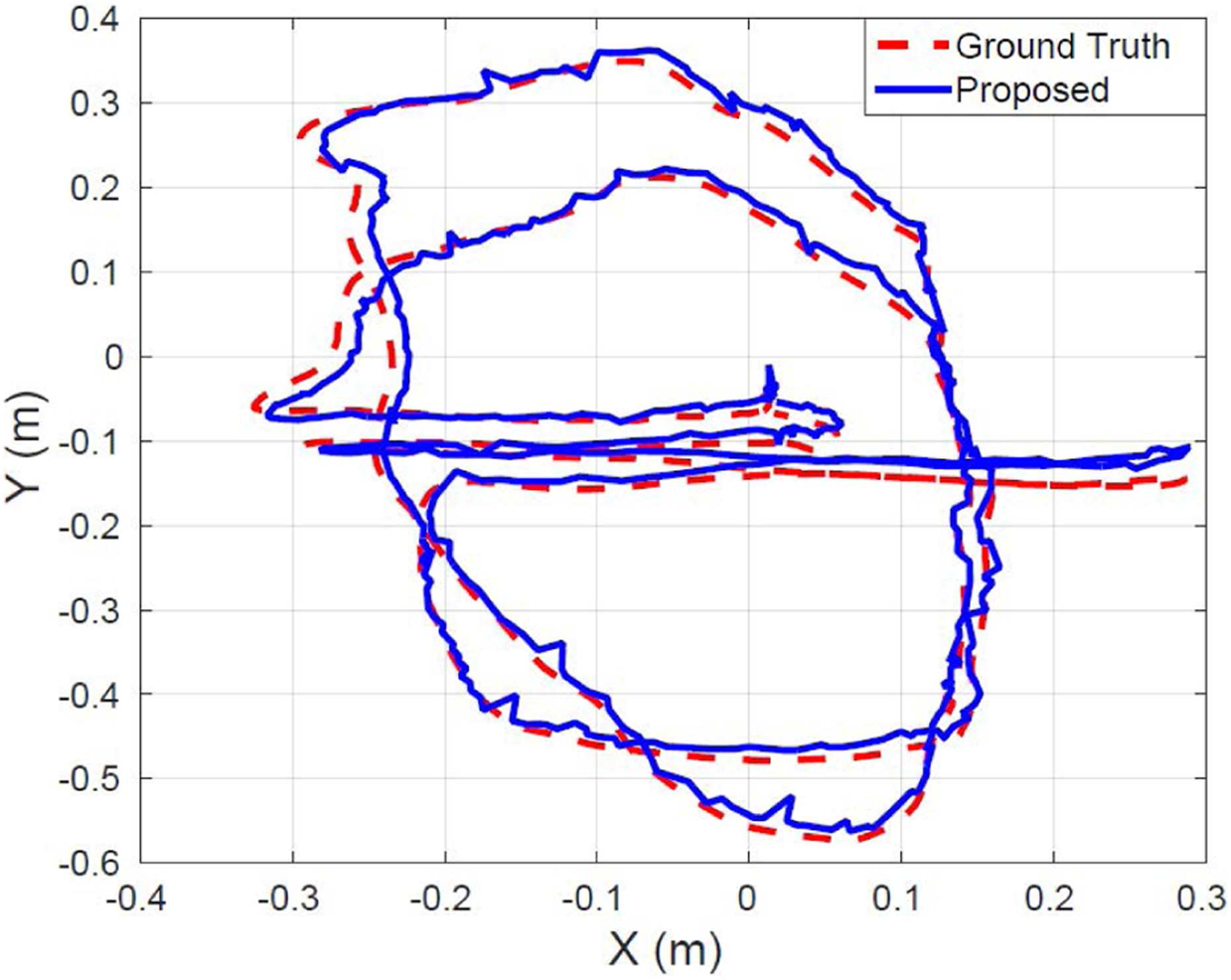
The experiment result of the robot pose estimation in 2-D environment.
Conclusion
In this article, we presented a robust handrail detection and pose estimation algorithm for handrail grasping of a free-flying robot. Since the proposed algorithm makes use of the geometric assumption that the handrails have cylinder types of shape and they are attached on a flat surface, it is capable of detecting and estimating various types of handrails with similar geometric constraints. The handrails on the ISS are the most challenging types among the other handrails since there are many cables and instruments attached together next to the handrails as well as varying lighting conditions. The proposed algorithm uses three tests, that is, gap distance test, cross point test, and side width test, to filter out false-positive handrail points and estimates the relative pose of the handrail to the robot body based on the estimated plane and line from the point cloud. The experimental results show that the proposed algorithm is able to filter out objects around the handrail and robustly estimate the handrail pose with various 3-D poses in static and dynamic conditions.
Future work includes the estimation of the target pose for the handrail perching and the state of the gripper on the handrail based on the kinematic model of the perching arm. The proposed algorithm will also be used for the EKF-based robot localization such that the Astrobee will use the handrail pose estimation as the measurement data of its pose during handrail perching process.
Footnotes
Acknowledgement
The authors would like to thank the Astrobee engineering team and the NASA Human Exploration Telerobotics 2 project for supporting this work.
Declaration of conflicting interests
The author(s) declared no potential conflicts of interest with respect to the research, authorship, and/or publication of this article.
Funding
The author(s) disclosed receipt of the following financial support for the research, authorship, and/or publication of this article: This work was supported by the NASA Game Changing Development Program (Space Technology Mission Directorate), ISS SPHERES Facility (Human Exploration and Operations Mission Directorate), the Ministry of Science, ICT and Future Planning, Korea, under the Information Technology Research Center support program (IITP-2017-2014-0-00639) supervised by the Institute for Information and communications Technology Promotion (IITP), and the Kumoh National Institute of Technology.
Supplemental material
Supplementary material for this article is available online.
References
Supplementary Material
Please find the following supplemental material available below.
For Open Access articles published under a Creative Commons License, all supplemental material carries the same license as the article it is associated with.
For non-Open Access articles published, all supplemental material carries a non-exclusive license, and permission requests for re-use of supplemental material or any part of supplemental material shall be sent directly to the copyright owner as specified in the copyright notice associated with the article.