
Abstract
While exploring complex environments, conventional mobile robots can overcome obstacles of limited height and jumping robots can overcome obstacles several times their own size. When jumping motion and wheeled or tracked motion are combined to form a composite motion, robots have even better ability to traverse rugged terrain. Therefore, we designed a wheeled hopping robot with a novel combustion-powered actuator and carried out structural design and experimental studies. The combustion-powered actuator has a unique inlet scheme and good sealing performance and is easy to install. The jump height equation was obtained by analyzing the combustion process. With the help of orthogonal array design methods, the factors that affect the wheeled hopping robot’s jumping height were analyzed to improve its key design parameters and optimize its jumping performance. Finally, experiments were performed with the actuator and the wheeled hopping robot. When the stoichiometric ratio of the mixed fuels nears complete combustion, the combustion-powered actuator can jump 7.5 m high with a payload of 3.75 kg and its own weight of 1.25 kg, and the wheeled hopping robot can jump 4.5 m high with a payload of 6 kg. Evaluating the robot’s performance in terms of energy efficiency reveals that it has a significant jumping advantage.
Introduction
With increasing demand in domains such as antiterrorism, disaster relief, and planetary exploration, mobile field robots have become a research focus. To cope with complex environments, mobile robots require the ability to traverse natural and artificial environments and structured and unstructured environments. To improve their environmental adaptability, mobile robots must have the ability to overcome obstacles such as ramps, vertical walls or fences, and ditches. Mobile robots consist mainly of wheeled robots, tracked robots, legged robots, and hybrid mobile robots. Wheeled robots are well adapted to flat and hard terrain, but they are unlikely to climb obstacles larger than half their wheel diameter. 1,2 However, improved wheeled robots may overcome obstacles close to double their wheel diameters. 3 Tracked robots can generally traverse rough and soft terrain, but the maximum obstacle height they can overcome remains limited. 4,5 Legged robots are usually good at coping with rugged and uneven terrain, but they are unable to climb obstacles greater than twice their leg length. 6,7 However, by means of leg structure design with wheeled features, novel legged robots are able to overcome obstacles higher than 1.3 times the length of one leg. 8,9 Furthermore, hybrid mobile robots usually integrate at least two locomotion modes to enhance their ability to adapt to the terrain, but the height of obstacles that can be traversed depends on a single locomotion mode. 10 –13
Jumping is a very effective way of traversing obstacles in the natural world. Most animals jump rather than use other means of traversing obstacles. By drawing inspiration from animals, various jumping robots, such as spring-loaded inverted pendulum jumping robots, 14 –18 articulated jumping robots, 19 –23 wheeled and rolling jumping robots, 24 –28 and flexible jumping robots, 29 –31 have been proposed for adaptation to complex terrain and for traversing obstacles in structured and unstructured environments. Moreover, individual jumping robots can easily overcome obstacles many times their own size. 32 –35 From the point of view of practical application, it is necessary to improve the mobility efficiency of jumping robots with the ability to traverse obstacles, so researchers have proposed hybrid robots that combine jumping with other locomotion modes, such as wheeled jumping robots. 24 –26 One of the key problems in the study of jumping robots is the jumping power source. According to their different driving modes, jumping power sources may be elastic, pneumatic, hydraulic, electrical, or combustive. The energy density of combustive energy is the highest among these power sources 36 and is two orders of magnitude higher than the electrical batteries with the best performance. 37 Therefore, combustive energy is an appropriate jumping power source for a hopping robot.
The urban hopper designed by the Sandia Lab and Boston Dynamics, which has a combustion-powered hopping actuator, is characterized by high output power, good mobility, and outstanding jumping performance (7.5-m jumping height). 26 The hopping actuator of SandFlea, developed by Boston Dynamics, is powered by gas fuel, and SandFlea is capable of jumping 8 m high. 38 Further details on SandFlea, such as its inner structure and working performance, are limited. In addition, a gas-fueled hopping actuator was proposed by Wang et al., 39 and an outdoor experiment demonstrated its ability to jump 2.1 m high with a payload of 2.43 kg and a body weight of 0.74 kg. However, Wang et al. 39 did not analyze factors that could affect the hopping actuator’s jumping performance. In addition to the design process and parameter analysis of the hopping actuator, this article illustrates the hopping robot’s inner structure, which was not given by Salton et al. 26 or by Wang et al. 39
In this article, the “Design of hopping actuator” section presents the structural design and working principle of the hopping actuator, including the parameter design of the returning spring, a theoretical analysis of the magnetic latch, and a strength analysis of the piston. In addition, the main factors that affect the jumping height are obtained by orthogonal array analysis. The “Design of wheeled hopping robot” section explicates the structural design and working principle of the hopping robot, including the design idea for the shock-absorbing wheel. The “Experiments” section describes two outdoor jumping experiments whose results verified the feasibility of the hopping actuator and the hopping robot. Finally, the “Evaluation of hopping performance” section uses the criterion energy efficiency to evaluate the overall performance of the proposed hopping actuator. The evaluation result shows that the hopping actuator’s performance lived up to the design expectations. Therefore, the hopping actuator shows promise as a power device for a hopping robot.
Design of hopping actuator
Selection of gas fuel
To reduce the weight of the hopping robot and improve the performance of the hopping actuator, a combustive fuel is an appropriate energy source. Because the onboard fuel should have a high energy density, we chose propane (C3H8) as the flammable gas and nitrous oxide (N2O) as the oxidizer for this study. Propane has an energy density of 13,900 Wh/kg, which is much higher than that of most flammable gases. 36 Nitrous oxide is used as the oxidizer to realize self-pressurization and to increase the hopping actuator’s power output. In addition, the two gases are nontoxic, harmless, and stable, which makes them environmentally friendly and easy to maintain.
The chemical reaction equation of the two gases is the oxidation of C3H8 by N2O

Therefore, the complete combustion reaction means that the gas mixture consists of one part C3H8 and 10 parts N2O. Only when the ideal charging ratio is realized can the actuator attain its maximum hopping performance.
Structure design
The main structure of the actuator is shown in Figure 1. The hopping actuator consists of a cylinder set, an inner hollow piston, a magnetic latch, an ignition device, and some other components.

Structure of the hopping actuator.
The hollow piston structure of the hopping actuator makes the most of the inner space of the actuator and allows a compact design. The mixture of fuel is charged into the inner space of the piston through a fuel inlet located in the pedestal. The exhaust gas and air can be gradually expelled from the main exhaust when the new fuel is charged into the chamber. The ignition process is realized by a glow plug, and the platinum filament attached to the glow plug is used as a catalyst to accelerate the chemical reaction. 37 The O-ring seal is installed into the groove of the piston to prevent fuel leakage. The inflation pressure in the combustion chamber is detected with a pressure sensor connected to the pressure detection hole. When the inflation process is complete and combustion is about to occur, the valve between the actuator and the sensor closes immediately to protect the sensor from high-pressure impact. In addition, the connection between the cylinder lid and the cylinder and the connection between the piston and the pedestal are realized by threads. Teflon tape is entangled in the external threads to ensure that the combustion chamber is well sealed. The dismountable cylinder lid makes the actuator easy to assemble and maintain. In addition, the buffer block can keep the undersurface of the piston from scraping and abrasion, and the cushion can alleviate impulsion of the outer edge of the piston with the top stepped surface of the cylinder.
The magnetic latch comprises an upper ring permanent magnet mounted in the cylinder and a lower ring permanent magnet mounted in the pedestal. The attraction force of a pair of ring permanent magnets is greater than that of a pair of cylinder permanent magnet sets (a set of cylinder magnets consists of 12 cylinder magnets) 39 because the contact area of the former is larger than that of the latter. In addition, a pair of ring magnets is easier to install on the actuator than the cylinder magnets, which makes the force of the magnet latch more controllable. Hence, a magnetic latch of ring magnets is more effective and reliable than a magnetic latch of cylinder magnets.
Compared to the actuator of a double-piston structure, 39 the actuator described in this article is equipped with only one piston with a hollow structure, as shown in Figure 2. Therefore, this kind of actuator has a more compact and simple structure. Because the actuator replaces the inner piston, the volume of the combustion chamber without the inner piston is greater, and thus the volume of the gas mixture in the chamber increases. Based on the structural design, this kind of actuator is easier to assemble and maintain.

Comparison between double-piston actuator (a) and proposed actuator (b); the cylinder and the outer piston are the same size.
Working principle
To actuate the explosive reaction, a high-power glow plug should be used as an ignition device. The working voltage of the glow plug applied to this actuator is 12 V, and its working current is 10 A. Such high power makes the temperature of the glow plug’s heating part increase quickly to 1000°C in 6 s. In the charging stage, the oxidizer (nitrous oxide) and the fuel (propane) are charged into the combustion chamber in a certain sequence. The glow plug is then energized to trigger the explosive reaction. It is should be noted that the gas mixture is charged only when the actuator is required to execute a hopping motion, unlike the continuous operation of an internal combustion engine.
After ignition, the pressure in the combustion chamber skyrockets because of the explosive reaction. The high-pressure gas pushes the piston downward against the ground, applying a reaction force to the cylinder. The cylinder’s great kinetic energy carries the piston off the ground when the piston reaches its maximum stroke (i.e. when the top stepped surface of the cylinder collides with the outer edge of the piston), thus completing the hopping motion. After the explosive reaction, some exhaust in the chamber is discharged through the exhaust emission holes, but most is expelled through the main exhaust outlet (see Figure 1). The piston then returns to its initial position via the restoring force of the spring and the attraction force of the magnetic latch, and the remaining exhaust in the chamber is expelled by the completion of a new charging cycle.
The volume of fuel is determined by the initial pressure, and the initial pressure in the chamber before the explosive reaction is determined by the magnetic force of the magnetic latch. Therefore, the stronger the magnetic force is, the higher the initial charging pressure is, and the higher the hopping robot can jump. Once the pressure of the gas mixture in the chamber is high enough, the lower magnet overcomes the magnetic force, the static friction of the O-ring seal, and the spring force and separates from the upper magnet. Because of the transient decay property of the magnetic force, a pair of ring permanent magnets is suitable for increasing and holding the inflation pressure of the gas mixture.
The magnetic latch is also helpful in returning the piston effectively and quickly to its initial position during the hopping stage. Although the piston can retract as a result of the restoring force of the spring, the spring force is too small to push the piston back when it nears its initial location. However, the piston can finally return to its initial position effectively because it is within the range of the magnet’s force.
Parameter design and analysis of components
Parameter design of the spring
The friction between the piston and the cylinder is generated from deformation of the O-ring seal mounted on the piston. The value of friction should be measured experimentally because it is closely related to the spring’s parameter design. Therefore, we can push the piston with a dynamometer relative to the cylinder, and the friction value can be roughly estimated by the dynamometer’s readings. A final friction value of 60 N was attained after several experiments.
When the explosive reaction in the chamber occurs, the high-pressure gas pushes the cylinder rapidly upward relative to the still piston, overcoming the resistance from the spring, the O-ring seal, and the magnetic latch. To minimize energy loss, the stiffness of the spring should be sufficiently low so that its restoring force is able to retract the piston.
A cylindrical helical spring with a rectangular wire can be applied to the actuator for improved shock resistance and compressive properties. The basic design principles of the spring are as follows
40
: 1. Determine the stiffness of the spring k = 2.5 N/mm by the condition of piston’s retraction. 2. Determine the shear modulus G = 83,000 MPa, the mean diameter of the coil D = 50 mm, and the width a = 3 mm and height h′ = 4 mm of the spring wire’s cross section (Figure 3). 3. Determine the maximum amount of compression S = 51 mm. Calculate the spring index C and the maximum spring force F′, and testify the rationality of a, h′, and C by the allowable stress formula


4. Calculate the number of active coils n with the stiffness calculation formula

Dimension parameters of the spring.
Therefore, all of the spring’s important parameters (a = 3 mm, h′ = 4 mm, G = 83,000 MPa, C = 50/3, n = 5) can be obtained. Figure 4 shows the factual picture of the spring.

Returning spring.
To minimize the actuator’s weight, the piston, cylinder, cylinder lid, and pedestal are all manufactured using the aluminum alloy LY12CZ. Its characteristics of a high specific strength and corrosion resistance make it suitable for the hopping actuator. The sliding bearing is fixed on the bottom stepped face of the cylinder so that the piston moves along a straight line. The inner surface of the cylinder and the outer surface of the piston are both polished well to decrease friction.
Magnet force analysis of the magnetic latch
Relevant studies and experiments have been performed to calculate the axial magnetic force of the permanent magnet rings magnetized in the axial direction. The axial magnetic force can be expressed as follows 41


In the magnetic force formulas, F Z is the axial magnetic force; B r is the remanence strength of the permanent magnet; n 0 is the number of magnet rings; L is the length of the axial magnetization of a single magnet ring; U 0 is the air permeability, U r is the relative permeability; d 1 is the inner diameter of the magnet ring; d 2 is the outer diameter of the magnet ring; Z is the axial distance between two magnet rings; and e is the radial offset between two magnet rings.
The relationship between the magnetic force F Z and the axial distance of the magnets Z can be analyzed with MATLAB [version R2015b] according to the formulas mentioned above. It can be concluded from Figure 5 that the magnetic force undergoes an obvious and rapid decrease as the axial distance of the magnets increases; this is the transient decay property of magnetic force.

Transient decay property of magnetic force.
Because the inner diameter of the piston d is 40 mm and the maximum initial charging pressure P 0 is set to 0.3 MPa, the required maximum magnetic force of the latch is

According to Tian et al. 41 and dimensions of the actuator, the values of the relevant parameters in the formulas above can be those shown in Table 1.
Parameter values of magnetic force calculation formulas.
The magnetic force F Z can be calculated to be 389.645 N by putting the relevant parameter values into magnetic force calculation formulas (6) and (7), which satisfies the requirement of magnetic latch force. However, the practical magnetic force might not be as great as the theoretical magnetic force due to various factors. The practical magnetic force should be measured by some relevant experiments.
Strength analysis of piston
The piston is under high pressure when the explosive reaction occurs. The piston should thus be strong enough to withstand the impact of the high-pressure gas. The strength of the piston can be roughly evaluated by ANSYS [version 14.0] Mechanical APDL simulation analysis. To simplify the analysis process, we can treat the pressure applied to the piston as a static force at the moment the explosive reaction occurs; thus, we perform linear static analysis for the piston. In the ANSYS software, 42 we can first construct the piston model and mesh it by parameter settings. Because of the piston’s symmetry, we need only construct and analyze one-quarter of the piston. The deformation nephogram and stress nephogram are shown in Figure 6(a) and (b), respectively.

(a) Deformation nephogram of the piston.(b) Stress nephogram of the piston.
From the simulation analyses, we can conclude that the piston’s maximum deformation is 0.0376 mm and that its maximum equivalent stress is 105 MPa. The yield strength of the piston material (LY12CZ) is 430 MPa; therefore, the piston’s strength satisfies the experimental requirement.
Orthogonal array design
The orthogonal array design is an effective design method for multiple-level and multiple-factor analysis. It picks up some representative points from the full-scale tests that are homodisperse and uniform. Its high efficiency, rapidness, and economy allow it to be applied to analyze the factors that affect the hopping robot’s jumping height and to improve the parameters of the hopping actuator.
Theoretically, the jumping height H can be expressed as

where M
0, M, and m
0 represent the mass of the hopping actuator, the payload, and the cylinder, respectively. W
t is the total work done by the explosive reaction,
According to the adiabatic reversible process equation of ideal gas 43

The work W t done by ideal gas during the adiabatic reversible process is

According to formula (10), formula (11) can be written as


The meanings of the symbols are as follows:
K: constant;
h: piston stroke;
P 1 and V 1: pressure (MPa) and volume (cm3), respectively, at the beginning of gas expansion when the piston remains in its initial position;
P 2 and V 2: pressure (MPa) and volume (cm3), respectively, at the end of gas expansion when the piston collides with the cylinder;
γ: adiabatic exponent of ideal gas (1.3);
T max: highest temperature of explosive reaction (4170 K);
T 0: environment temperature (293 K);
P 0: initial charging pressure (MPa) before explosion;
m′, n′: ratio of the number of gas molecules before and after explosion, respectively,
r, h
0: inner radius (cm) and height (cm) of combustion chamber, respectively,
Therefore, the jumping height H is

By putting the known parameter values into formula (16), H can be expressed as

We can design the orthogonal array in three and seven factors. 44 The value of each variable is shown in Table 2.
Parameter values table of orthogonal array.

By intuitive analysis of Table 2, we can attain the data table of the orthogonal array. The mean value of each level in each factor is calculated according to the experimental results, and the range of each factor is determined by its three mean values. The greater the range is, the greater is the influence of the variable on the jumping height. It can be observed from the data table of the orthogonal array that r has the greatest influence on jumping height. According to mean value 1 to mean value 3, the optimal combination of parameter values is m 0 = 0.6 kg, M = 4 kg, M 0 = 0.88 kg, r = 2 cm, h = 5 cm, P 0 = 0.4 MPa, and T 0 = 273 K or 300 K.
The effect curve of the orthogonal array (Figure 7) is drawn according to Table 3, from which it can be seen that the relationships between the jumping height H and r or P 0 are positive. However, the intuitive analysis only determines the primary and secondary relationships of various factors that affect the jumping height, and it fails to offer a standard by which to evaluate and judge the significance of various factors’ effects. Thus, analysis of variance is necessary to make up for the shortcomings of intuitive analysis.
Effect curve of orthogonal array.
Analysis of variance table.
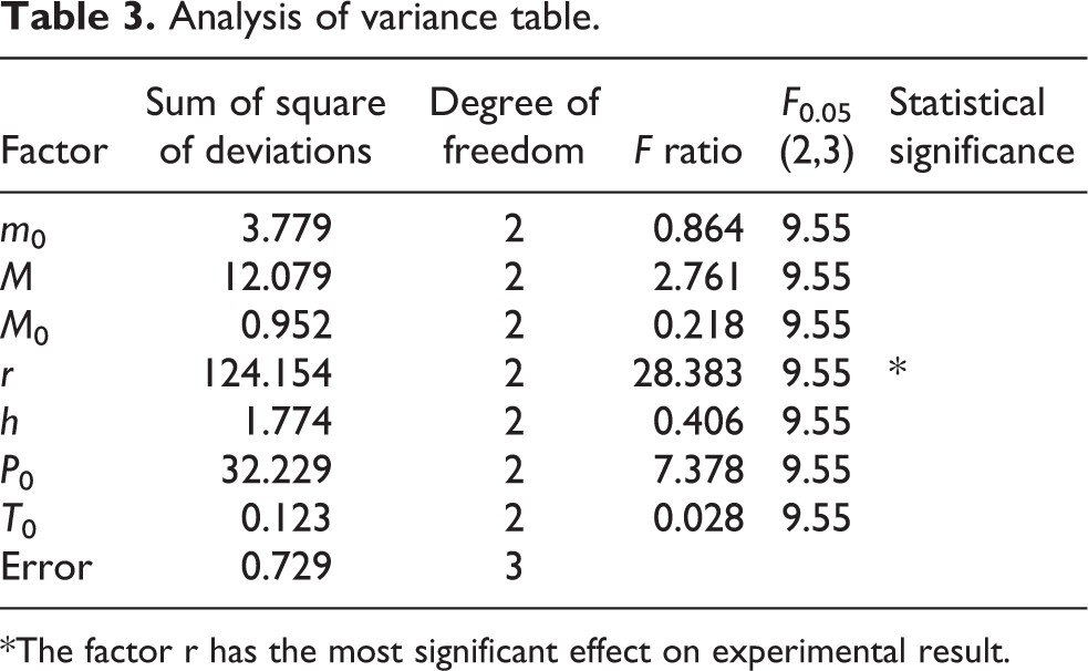
*The factor r has the most significant effect on experimental result.
It is obvious that the F ratio of r is greater than the critical value of F from the analysis of variance table (Table 3); therefore, factor r (F ratio = 28.383) has the most significant effect on the experimental result, followed by factor P 0 (F ratio = 7.378). Hence, the values of r and P 0 can be appropriately increased within a certain range to improve the hopping actuator’s jumping ability.
Design of wheeled hopping robot
Shock-absorbing wheel
According to the hopping robot’s working process, the requirements for the wheel are as follows: The wheels should be able to absorb part of the hopping robot’s landing energy to prevent damage to the robot’s components. To minimize the robot’s weight, the wheel’s structure should be as simple as possible. The wheels should not deform obviously when the robot adopts wheel motion.
A honeycomb structure can thus be a suitable option for the wheels because of its excellent impact resistance and simple structure. A polyurethane material is chosen for its low density, high strength, and good elasticity. 45
The wheel comprises an inner ring, an outer ring, wheel spokes, and tread. The inner ring is connected to the axle, and the outer ring encloses the wheel spokes. The wheel spokes are designed like a honeycomb and are flexible when pressed. In addition, an appropriate damping layer between the outer ring and the tread can help to absorb the landing energy and enhance the wheel’s stiffness.
After calculating the dimensions of the wheel, we can construct a wheel model with CAD software and manufacture it with injection molding. The actual wheel is shown in Figure 8.
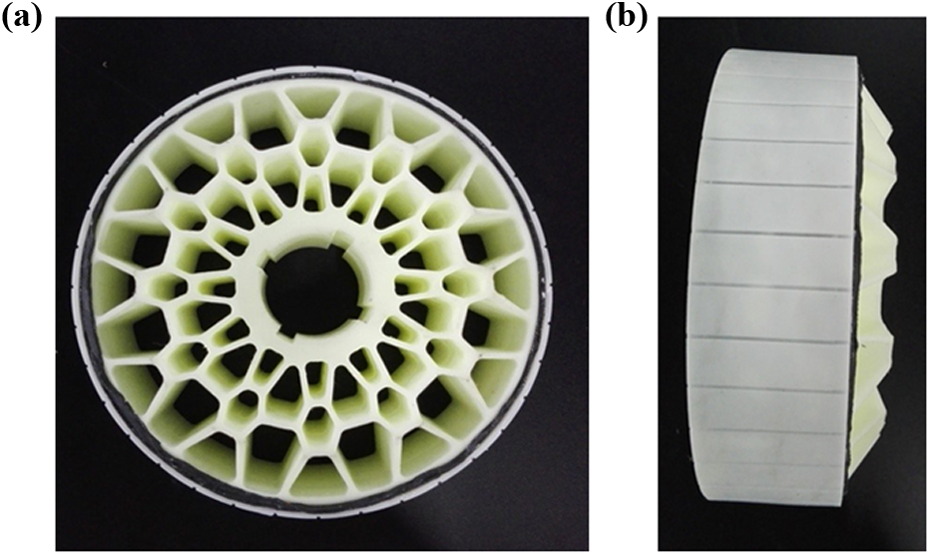
(a) Front view of the shock-absorbing wheel. (b) Side view of the shock-absorbing wheel.
Structure of the hopping robot
The hopping robot includes five modules: the driver module (shock-absorbing wheels, motors, and bevel gears), the angle-adjustment module (supporting legs, servos, and spur gears), the control module (control circuit board), the power module (battery set), and the hopping actuator module (hopping actuator and solenoid valve).
The layout of the hopping robot is also closely relevant to its performance. Five factors require attention in the design of the overall layout: (1) the center of gravity should be in the rear; (2) the actuator’s piston should not stretch beyond the range of the wheel; (3) the components of the robot should be mounted symmetrically in case the robot deflects to the left or right while jumping; (4) the robot does not distinguish upper and lower surfaces; and (5) the supporting legs can be driven both clockwise and anticlockwise within a large range.
In addition, the stiffness and strength of the chassis and the brackets on which the motors are mounted should be high in case of malposition of the components or deformation of the robot. Therefore, the final overall layout is shown in Figure 9. The prototype is demonstrated in Figure 10; its dimension is 374 × 364 × 150 mm3, with a total weight of 7.25 kg.

Layout of the hopping robot.
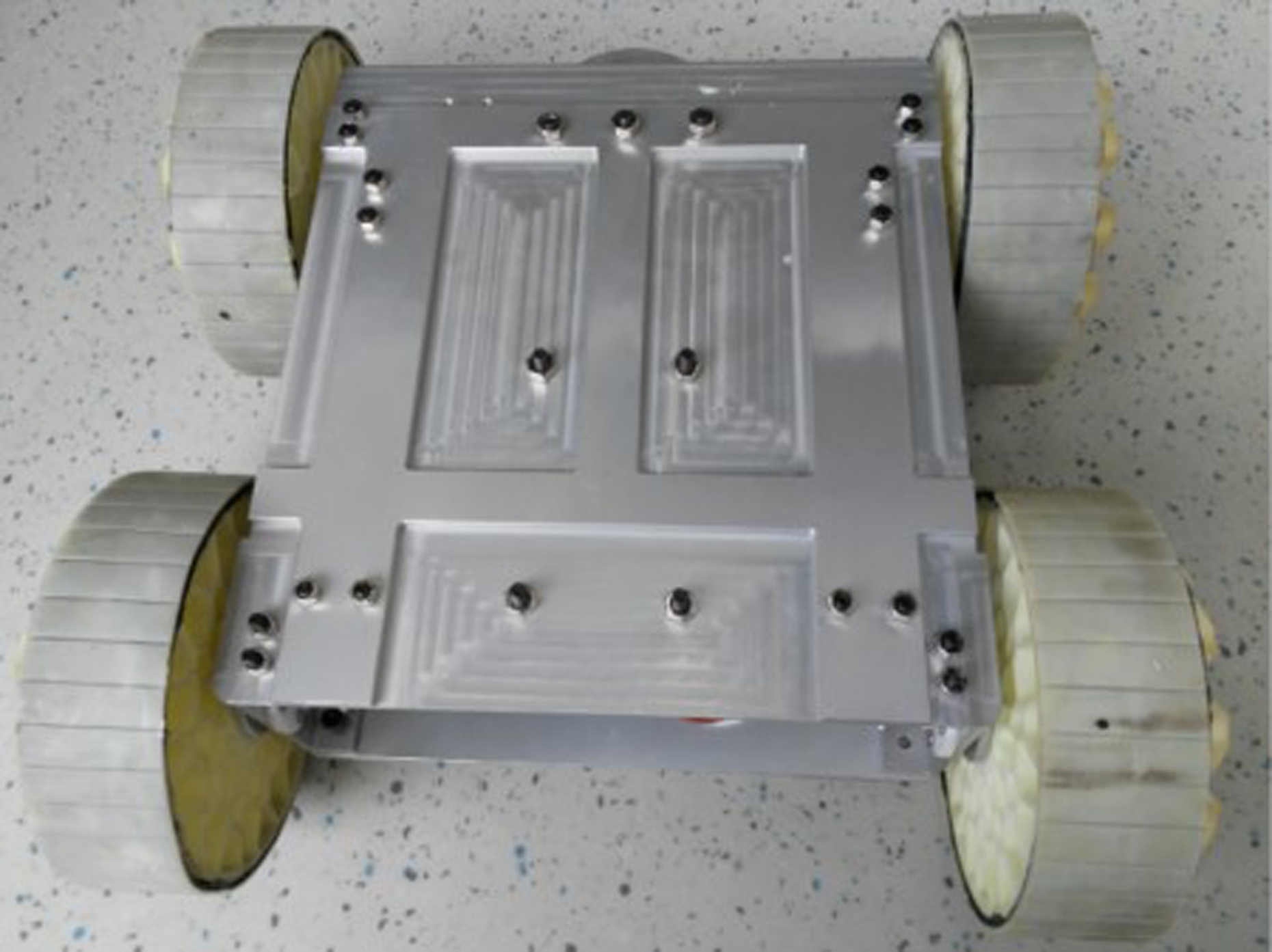
Prototype of the hopping robot.
Working principle
To simplify the layout, only the front shock-absorbing wheels are driven by direct current motors, which means that only the front wheels are drive wheels. With its four wheels, the hopping robot is capable of linear motion and differential steering. The robot’s angle with respect to the ground can be adjusted by the supporting legs, which are driven by servos. The jumping height and distance of the robot can be changed by varying this angle. The driver module, the angle-adjustment module, the power module, and the hopping actuator module are all controlled by the control circuit board. The wireless transmission module on the control circuit board enables communication between the hopping robot and the wireless terminal. Therefore, the hopping robot can work smoothly by receiving remote commands from the wireless terminal.
The essential component of the hopping robot in this article is the hopping actuator. At present, the robot can only hop once due to the lack of onboard fuel. In the hopping stage, the robot elevates itself with its supporting legs after charging fuel into the actuator. The appropriate elevation angle with respect to the ground should be between 45° and 90° to obtain a suitable launch trajectory. The closer the elevating angle is to 90°, the higher the hopping robot can jump. The hopping actuator can then propel the entire hopping robot upward and over an obstacle. While the robot is still in the air, the piston resets gradually and the supporting legs also return to their initial position to avoid damage.
Experiments
Experiments with the hopping actuator
Seal detection experiment
As Figure 1 shows, the combustion chamber is sealed by threads entangled with Teflon tape and the seal ring. After the hopping actuator filled with compressed air is put into the water, we can estimate the sealing quality by the amount of bubbles that rise from the actuator. At first, the actuator appeared to have poor sealing quality because of the appearance of obvious bubbles. After the amount of Teflon tape was increased, the sealing quality was obviously improved (Figure 11) to basically satisfy the requirement of an explosive reaction.
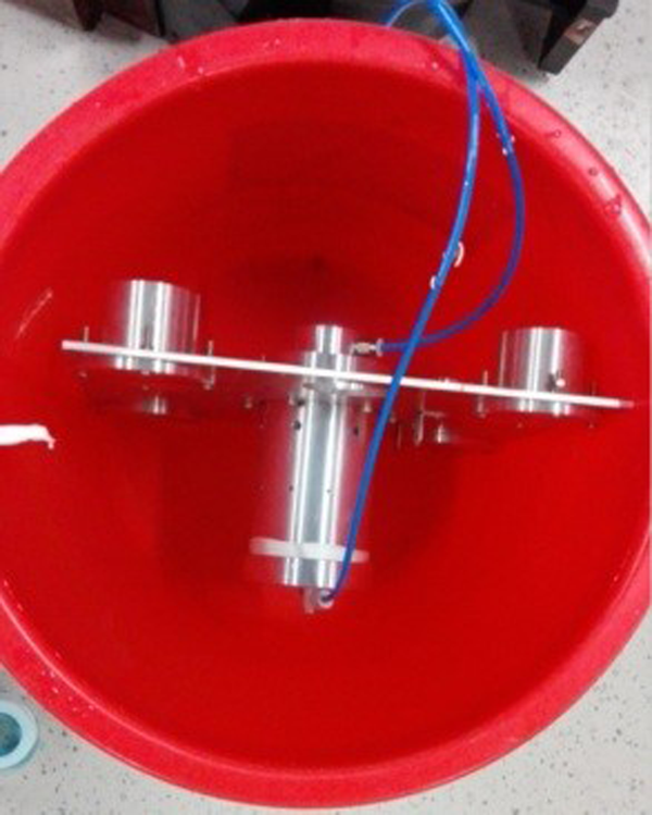
A hopping actuator with good sealing quality.
Outdoor jumping experiment
After a series of indoor experiments, the performance of the hopping actuator was ensured, and an outdoor jumping experiment was carried out to evaluate the actuator’s real jumping ability.
In the outdoor experiment, a 3.75-kg load was attached to the 1.25-kg hopping actuator to test its load capacity. Figure 12 (a) and (b) shows the total weight of the experiment prototype. The relay was used as a long-distance wireless switch to ensure the operator’s safety, which meant that the actuator’s glow plug and the battery were connected by the relay. The relay and the battery were fixed symmetrically to the actuator to allow it to jump vertically. The experimental prototype is shown in Figure 13.

(a). Total weight of the experiment prototype. (b). Total weight of the experiment prototype

Prototype of the hopping actuator in the outdoor experiment.
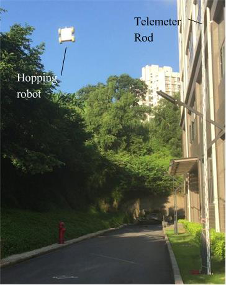
The actuator’s jumping height was measured with a telemeter rod standing upright on the ground. In addition, a tether was attached to the experimental prototype in case of an unpredictable incident. To testify to the actuator’s maximum jumping ability, the charging ratio (i.e. the ratio of propane to nitrous oxide) was 1:10 to realize the ideal inflation ratio. Hence, the charging process was as follows: (1) 0.05 MPa (gauge pressure) nitrous oxide was charged into the combustion chamber; (2) 0.03 MPa propane was charged into the combustion chamber so that the pressure gauge read 0.08 MPa; and (3) 0.15 MPa nitrous oxide was charged into the combustion chamber so that the pressure gauge read 0.23 MPa.
By means of the charging method, the propane and nitrous oxide were mixed sufficiently to contribute to an efficient explosive reaction. The glow plug was then energized to ignite the fuel, and the hopping actuator with the payload jumped after 6 s. From Figure 14, the height of the jump can be estimated at more than 7 m.

Experiment with the hopping actuator.
The actual movement of the experimental prototype was captured by a high-speed camera, and therefore the real-time height and velocity can be estimated from the trajectory of the experimental prototype. Figure 15 (a) shows the difference between the experimental hopping height curve and the theoretical hopping height curve, and Figure 15 (b) compares the experimental velocity curve and the theoretical velocity curve of the experimental prototype. It is obvious that the experimental maximum height (7.4 m) is lower than the theoretical maximum height (8.5 m), which may be due to air resistance during the jump and an imperfectly vertical jump.
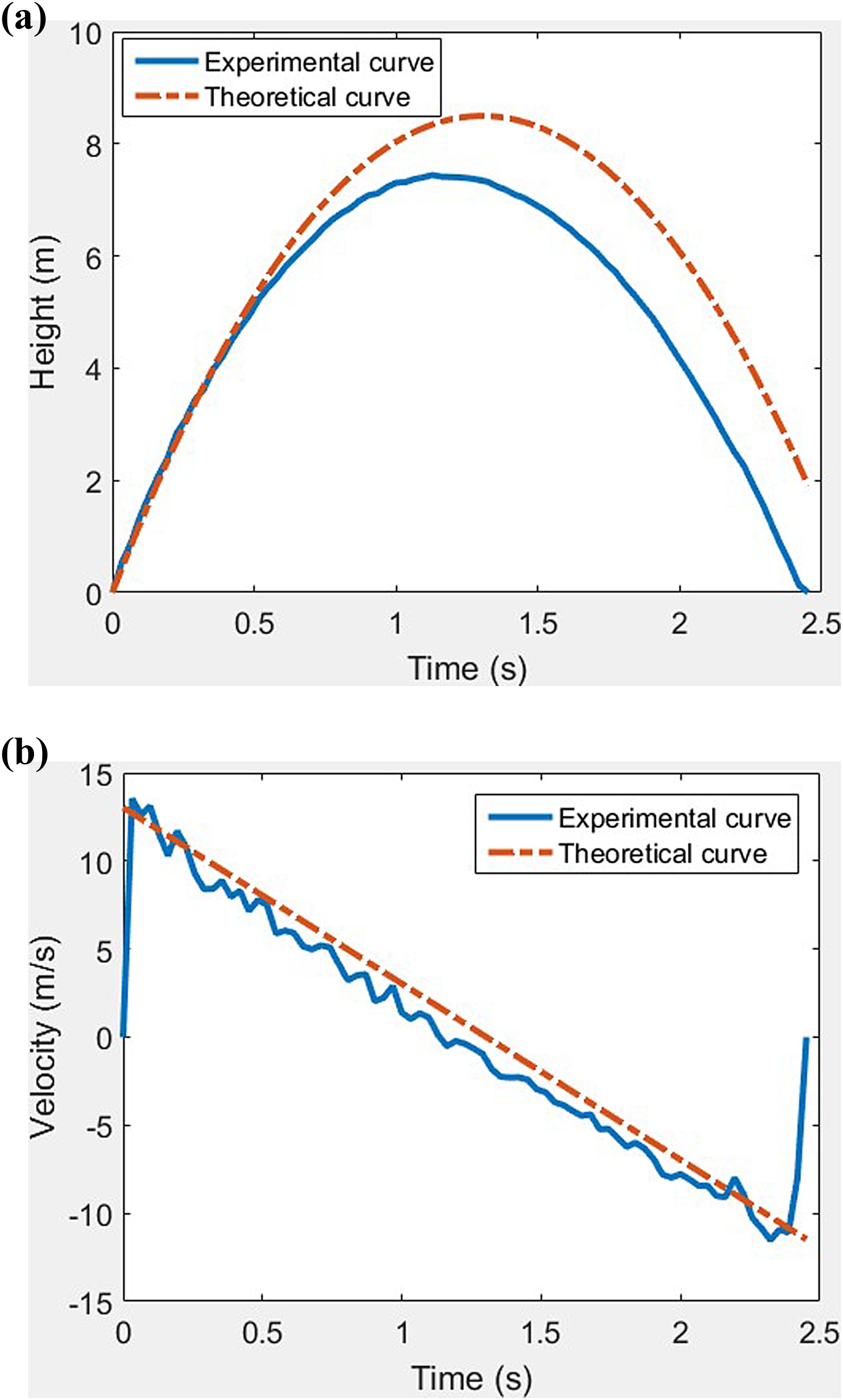
(a) Height curves of the experimental prototype. (b) Velocity curves of the experimental prototype.
Experiment of the wheeled hopping robot
The weight of the hopping robot was 7.25 kg after assembly. Because the hopping actuator (1.25 kg) carrying a payload of 3.75 kg is capable of jumping more than 7 m, the jumping height of the hopping robot can be theoretically evaluated to be about 5 m. To maximize the jumping height, the elevating angle was set to be 85°. As shown in Figure 16, the hopping robot jumped a bit over 5 m, thus verifying the previous evaluation. In addition, this experiment shows excellent shock-absorption ability of the wheels because of the well-designed structure parameters of honeycomb structure and proper stiffness of the wheels. The wheels deformed obviously during robot’s landing so that the impact energy was effectively absorbed and the robot body and all the components were well-protected. After that the wheels restored its original shape quickly, making sure its normal motion on flat ground.
Experiment with the hopping robot.
Evaluation of hopping performance
Wang et al. 39 proposed a metric called the normalized payload to evaluate the performance of hopping robots. The normalized payloads of the robots mentioned in that paper were listed, but the details of the payloads of some robots were limited, and the definition of payload was not explained clearly.
The design of the hopping actuator is inspired by the two-stroke engine, and the working principle of the former to convert the internal energy of the fuel to the kinetic energy of the piston, which is similar to that of a two-stroke engine. Therefore, the combustion-powered hopping actuator can also be treated as an internal combustion engine. Because energy efficiency is an important performance index of common engines, we hereby use the new criterion, energy efficiency, to differentiate from the normalized payload 39 and to evaluate the proposed hopping actuator’s overall performance. The energy efficiency can be expressed as

where We is the useful work done by the explosive reaction, and W t is the total work done by the explosive reaction. Obviously, We is the maximum gravitational potential energy of the hopping robot.

where Mr is the hopping robot’s total weight and H is its maximum jumping height. The explosive reaction in the combustion chamber of the hopping actuator can be seen as adiabatic expansion and as working outside of ideal gas.
Combining formulas (12) and (19), the energy efficiency η is

The parameter values in (20) are listed in Table 4, so η can be calculated by putting each parameter value into (20); the final result is η =78.5%.
Parameter values of energy efficiency formula (20).
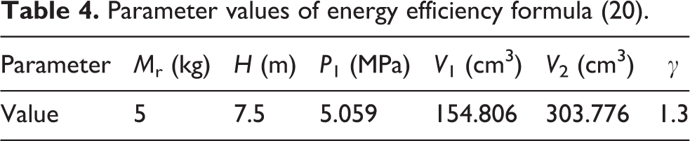
According to Grimaldi and Millo, 46 the energy efficiency of common gasoline engines and diesel engines is 20–30% and 30–45%, respectively. Our hopping actuator has better energy efficiency than normal internal combustion engines. The difference in energy efficiency might be caused by the manner in which they work: the internal combustion engine works continuously, whereas the hopping actuator works intermittently, thus the former dissipates much more heat than the latter. In addition, the energy efficiency of the proposed hopping actuator also benefits from factors such as its good sealing quality, optimal charging ratio, and appropriate catalyst. Its high energy efficiency means that the hopping robot can jump more times with a given amount of onboard fuel.
Conclusions
A wheeled hopping robot with a combustion-powered actuator is proposed in this article. The structure and working principle of the hopping actuator are explicated, including the parameter design of the returning spring and theory analysis of the magnetic latch. The strength reliability of the piston is validated with ANSYS software. In addition, the related parameters of the hopping actuator that affect its jumping performance are analyzed through an orthogonal array. The structure and working principle of the hopping robot are then interpreted, and its feasibility is verified in a series of experiments. Finally, a criterion named energy efficiency is used to compare the overall performance of the proposed hopping actuator with that of an internal combustion engine, and the result shows that the proposed hopping actuator lives up to the design expectation.
Although the jumping ability of the hopping robot is outstanding, there is still plenty of room for improvement. In future studies, the structure of the hopping actuator will be further optimized to increase its overall performance. For example, improving the sealing quality of the combustion chamber will help to make the most of the fuel’s chemical energy. Improving the performance of the magnetic latch could increase the initial charging pressure and thus increase the energy generated by the explosive reaction. In addition, the fuel should be carried aboard the hopping robot for automatic charging and to allow the robot to jump multiple times. The robot’s mechanical structure should also be optimized to minimize its weight because excessive weight might limit its flexibility, jumping performance, and load capacity. Therefore, the requirements of high strength and light weight should be considered in the design process of second-generation hopping robots.
A jumping distance experiment should be carried out because jumping distance is also a key indicator of a hopping robot’s performance. Various launch trajectories (and thus various jumping distances) can be realized by adjusting the robot’s launch angle. Real-life terrain surfaces are complex. Although the hopping actuator’s performance is outstanding on a normal road, its behavior on soft ground might not be satisfactory. Therefore, corresponding measures, such as increasing the contact area between the piston and the ground, should be adopted to decrease the pressure applied to the ground.
Finally, some relevant sensors, such as vision and laser sensors, should also be integrated into the wheeled hopping robot. With the help of necessary sensors, the hopping robot would be capable of automatic path planning, motion control, and obstacle avoidance, and its practical applicability in military reconnaissance, antiterrorism, rescue operations, and other fields would be greatly enhanced.
The hopping actuator proposed in this article provides new design ideas for the development of a hopping robot powered by gas. The orthogonal array analysis of the parameters that affect the hopping actuator’s jumping height can be the theoretical basis for further design of the hopping actuator. In addition, the structural design, experimental method, and data presented provide a reference that can be used for future developments of wheeled hopping robots.
Footnotes
Declaration of conflicting interests
The authors declared no potential conflicts of interest with respect to the research, authorship, and/or publication of this article.
Funding
The authors disclosed receipt of the following financial support for the research, authorship, and/or publication of this article: This work was financially supported by State Key Laboratory of Robotics and Systems, China (SKLRS201701B), Joint Funds of the National Natural Science Foundation of China (grant no. U1613201), in part by the Science and Technology Project of Guangdong, China (grant no. 2016A010102004), and in part by Shenzhen Research Funds (JCYJ20170413104438332, JCYJ20160427183553203, and GJHZ20170313113529978).